
WARNING SYSTEMS
2.4L
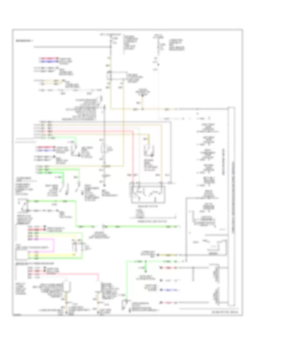
2.4L, Chime Wiring Diagram for Honda Crosstour EX 2014

List of elements for 2.4L, Chime Wiring Diagram for Honda Crosstour EX 2014:
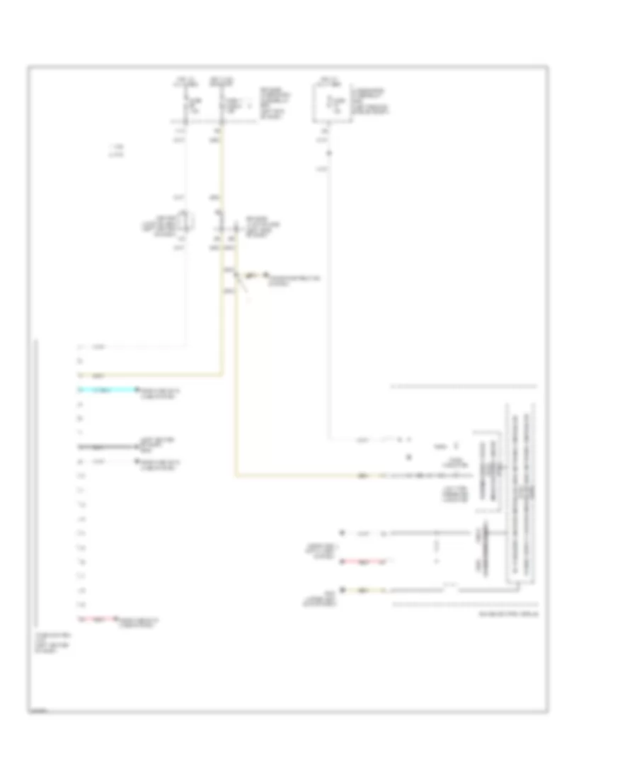
2.4L, Tire Pressure Monitoring Wiring Diagram for Honda Crosstour EX 2014
List of elements for 2.4L, Tire Pressure Monitoring Wiring Diagram for Honda Crosstour EX 2014:
3.5L
3.5L, Chime Wiring Diagram for Honda Crosstour EX 2014
List of elements for 3.5L, Chime Wiring Diagram for Honda Crosstour EX 2014:
3.5L, Tire Pressure Monitoring Wiring Diagram for Honda Crosstour EX 2014
List of elements for 3.5L, Tire Pressure Monitoring Wiring Diagram for Honda Crosstour EX 2014:
