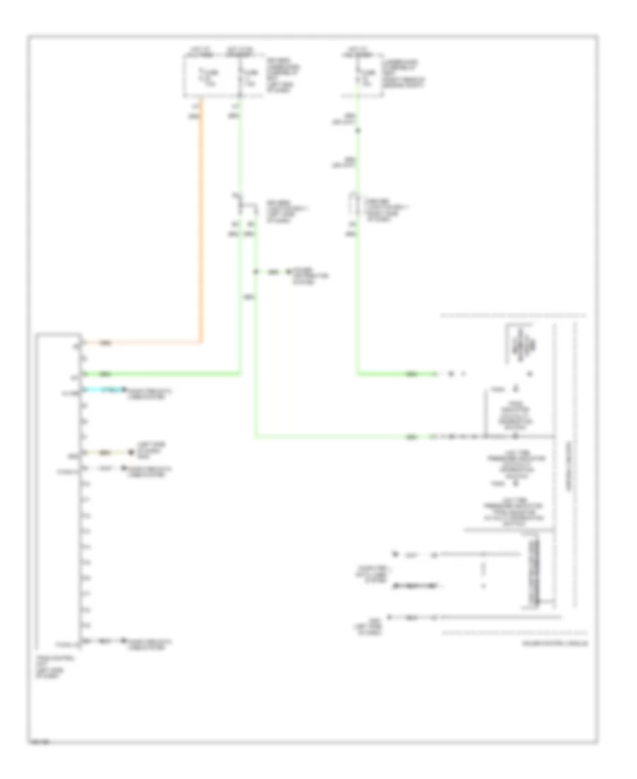
WARNING SYSTEMS
Chime Wiring Diagram for Honda Odyssey Touring 2013

List of elements for Chime Wiring Diagram for Honda Odyssey Touring 2013:
- "b" pillar)
- (left side of dash) g402
- 0) off 1) park 2) auto 3) head
- A48
- A49
- B-can hi
- B-can lo
- B-can transceiver
- Beeper
- Brake system indicator
- C11
- C16
- C22
- C302
- C601
- C604
- Center junction box (right side of dash)
- Combination light switch
- Computer data lines system
- Control circuits
- Door open indicator
- Driver's door switch (at driver's
- Driver's micu
- Driver's seat belt buckle switch (under driver's seat)
- Driver's under-dash fuse/relay box (left end of dash)
- E22
- F-canh
- F-canl
- Flbc
- Fr dr sw l
- Fuse 10a
- Fuse 7.5a
- G401 (left side of dash)
- G601 (under driver's seat)
- Gauge control module
- Gnd (lighting)
- H/l low sw
- H/l off sw
- H10
- Headlight switch
- Hot at all times
- Hot in on or start
- Ig key sw
- Ig1 mtr
- Ignition key light
- Ignition key switch
- Interior lights system
- J/c c103 (top right side of engine)
- J/c c104 (top right side of engine)
- Lights on indicator
- Low oil pressure ind
- P13
- P15
- P17
- P19
- Parking brake switch (on parking brake pedal assembly)
- Pcm (right rear of engine compt)
- Pnk
- Poil
- Power tailgate indicator
- Red
- Rocker arm oil pressure sensor (under engine)
- Seat belt reminder ind
- Sg1
- Sg2
- Small lt sw
- Srs unit (under middle of dash)
- Steering lock assembly
- Transceiver f-can
- Under-hood fuse/relay box (right rear of engine compt)
- Vcc6
- W/ memory
- W/o memory
Tire Pressure Monitoring Wiring Diagram for Honda Odyssey Touring 2013
List of elements for Tire Pressure Monitoring Wiring Diagram for Honda Odyssey Touring 2013:
- (left side of dash) g402
- Center junction box 1 (right side of dash)
- Computer data lines system
- Control circuits
- Driver's junction box 1 (left side of dash)
- Driver's under-dash fuse/relay box (left end of dash)
- F-can hi
- F-can lo
- Fast controller area network transceiver
- Fuse 10a
- Fuse 7.5a
- G401 (left side of dash)
- Gauge control module
- Gnd
- Hot at all times
- Hot in on or start
- Ig1
- Information display (mid)
- K-line
- Low tire pressure indicator (w/o multi- information switch)
- Low tire pressure indicator/ tpms indicator (w/ multi-information switch)
- Multi-
- Power distribution system
- Tpms control unit (left side of dash)
- Tpms indicator (w/o multi- information switch)
- Under-hood fuse/relay box (right rear of engine compt)