WARNING SYSTEMS
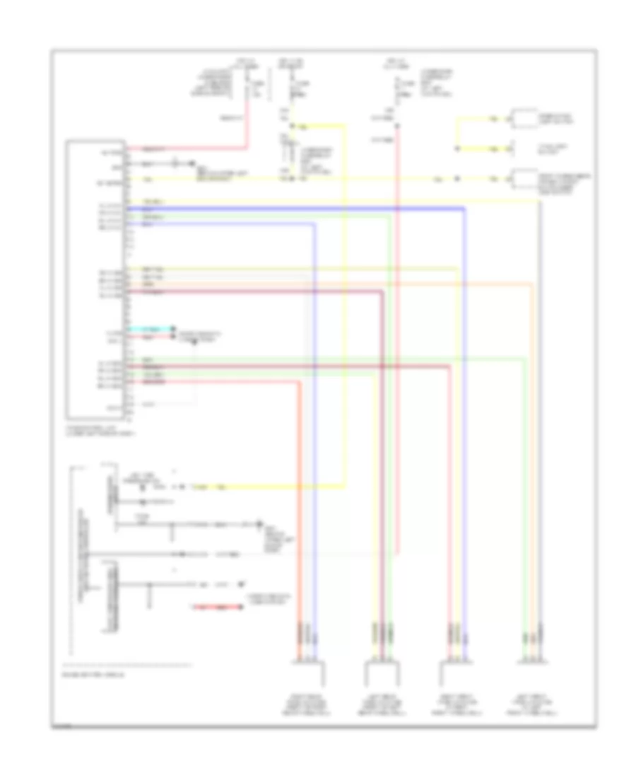
Tire Pressure Monitoring Wiring Diagram for Honda Ridgeline RTS 2009
List of elements for Tire Pressure Monitoring Wiring Diagram for Honda Ridgeline RTS 2009:
- +b tpms
- A10
- A19
- A20
- Auxiliary under-hood fuse box (left side of engine compt)
- Can h
- Can l
- Combination light switch
- Computer data lines system
- Fast controller area network transceiver
- Fl ini sig
- Fl lf gnd
- Fl lf ini+
- Fr ini sig
- Fr lf gnd
- Fr lf ini+
- Front passenger's power window switch/door lock switch
- Fuse 7.5a
- G401 (behind upper left end of dash)
- Gauge control module
- Gnd
- Hot at all times
- Hot in on or start
- Ig1 meter
- K-line
- Left front tpms initiator (in left front wheelwell)
- Left rear tpms initiator (front of left rear wheelwell)
- Low tire pressure ind
- N38
- Red
- Right front tpms initiator (in right front wheelwell)
- Right rear tpms initiator (front of right rear wheelwell)
- Rl ini sig
- Rl lf gnd
- Rl lf ini+
- Rr ini sig
- Rr lf gnd
- Rr lf ini+
- Tpms control unit (under left side of dash)
- Tpms ind
- Under-dash fuse/relay box (at left kick panel)
- Vtm-4 lock switch
- Warning drive circuit
- X34
- X35
 English