WARNING SYSTEMS
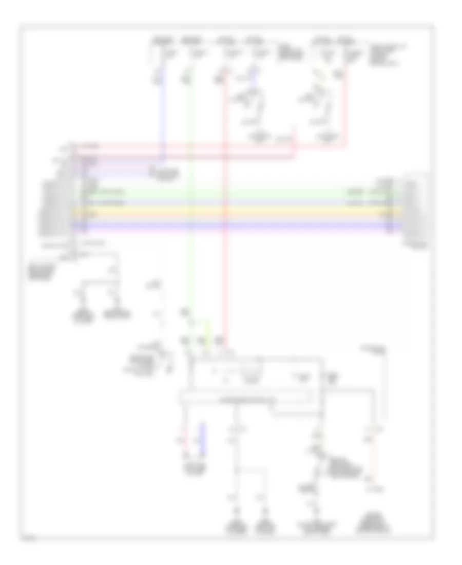
Warning Systems Wiring Diagram for Infiniti G35 x 2006
List of elements for Warning Systems Wiring Diagram for Infiniti G35 x 2006:
- 15a
- 4b m5
- 8a m4
- Air bag diagnosis sensor unit (under rear of center console)
- B5 (on left front side of passenger compt floor)
- Bat
- Body control module (bcm) (behind left kick panel)
- Buzzer
- Can-h
- Can-l
- Comb sw in 1
- Comb sw in 2
- Comb sw in 3
- Comb sw in 4
- Comb sw in 5
- Comb sw out 1
- Comb sw out 2
- Comb sw out 3
- Comb sw out 4
- Comb sw out 5
- Combination meter
- Combination switch
- Computer data lines system
- Door ind
- Door sw (dr)
- Driver seat belt buckle switch (in driver seat belt buckle)
- Driver side front door switch (coupe : in left "b" pillar)
- Fuse 1 10a
- Fuse 14 10a
- Fuse 15a
- Fuse 19 10a
- Fuse 21 10a
- Fuse block (j/b) (behind left kick panel)
- Fuse, fusible link & relay box (at right rear of engine compt)
- Fusible link f 50a
- Gnd
- Hot at all times
- Hot in on or start
- Ign
- Input 1
- Input 2
- Input 3
- Input 4
- Input 5
- Key sw
- Key switch
- M19
- M20
- M30 (behind instrument cluster)
- M55
- M66 (behind right side of dash)
- Output 1
- Output 2
- Output 3
- Output 4
- Output 5
- Pnk
- Seat belt ind
- Unified meter control unit
- W/ intelligent key
- W/o intelligent key
 English