WARNING SYSTEMS
Chime Wiring Diagram for Infiniti M35 2008

List of elements for Chime Wiring Diagram for Infiniti M35 2008:
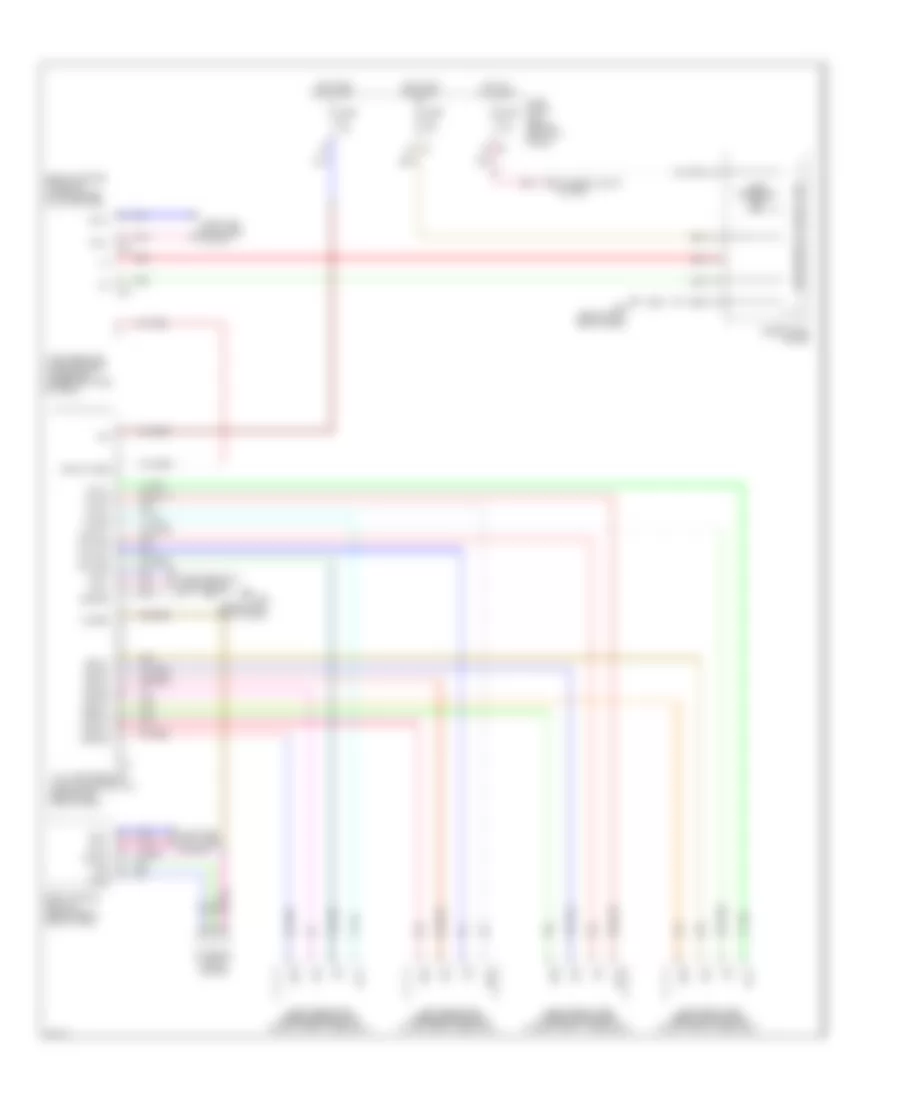
Tire Pressure Monitoring Wiring Diagram for Infiniti M35 2008
List of elements for Tire Pressure Monitoring Wiring Diagram for Infiniti M35 2008: