WARNING SYSTEMS
Chime Wiring Diagram for Infiniti Q50 2014

List of elements for Chime Wiring Diagram for Infiniti Q50 2014:
- (lower right center of dash) (hybrid) m111
- 28c m133
- B105 (left "c" pillar)
- B18
- B41
- Bat (fuse)
- Bat pwr sply
- Bcm (body control module) (right end of dash)
- Buzzer
- Can-h
- Can-l
- Comb sw in 1
- Comb sw in 2
- Comb sw in 3
- Comb sw in 4
- Comb sw in 5
- Comb sw out 1
- Comb sw out 2
- Comb sw out 3
- Comb sw out 4
- Comb sw out 5
- Combi sw in 1
- Combi sw in 2
- Combi sw in 3
- Combi sw in 4
- Combi sw in 5
- Combi sw out 1
- Combi sw out 2
- Combi sw out 3
- Combi sw out 4
- Combi sw out 5
- Combination meter
- Combination switch
- Computer data lines system
- Computer data lines system m93 (left end of dash)
- Driver side front door switch
- Driver side seat belt buckle switch
- Drv dr sw
- E25
- Except hybrid
- Fuse & fusible link block (on battery positive (+) post)
- Fuse & fusible link block 1 (top of li-ion battery assembly)
- Fuse 6 10a
- Fuse block (j/b) (left kick panel)
- Fusible link m 40a
- Fusible link t 40a
- Gnd
- Hot at all times
- Hybrid
- M108 (except hybrid) (upper left side of dash)
- M13
- M14
- M15
- M17
- M19
- M40
- M57
- M58
- Parking brake switch (base of parking brake lever assembly)
- Pnk
- Switch signal parking brake sw sig
- T25
- Tan
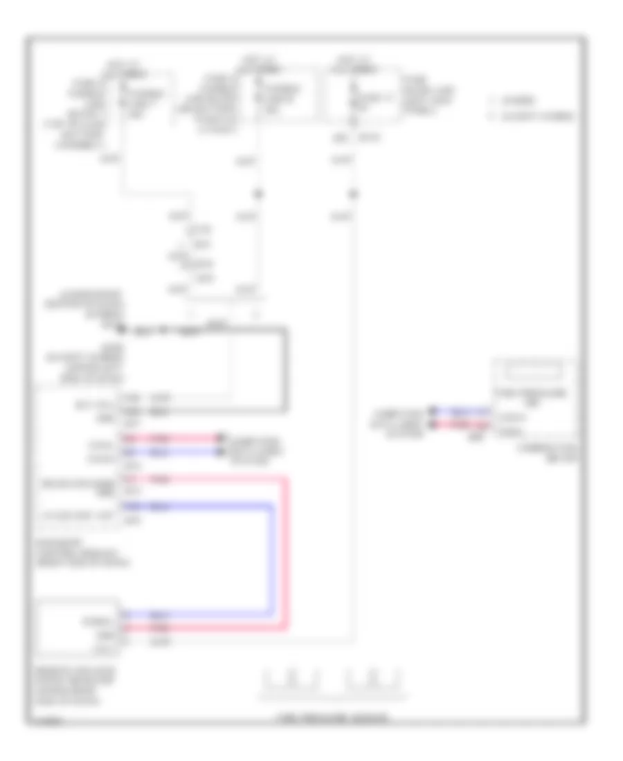
Tire Pressure Monitoring Wiring Diagram for Infiniti Q50 2014
List of elements for Tire Pressure Monitoring Wiring Diagram for Infiniti Q50 2014:
- (lower right center of dash) (hybrid) m111
- +12 v
- B18
- B41
- Bat (f/l)
- Bcm (body control module) (right end of dash)
- Can-h
- Can-l
- Combination meter
- Computer data lines system
- Except hybrid
- Fuse & fusible link block (on battery positive (+) post)
- Fuse & fusible link block 1 (top of li-ion battery assembly)
- Fuse 17 5a
- Fuse block (j/b) (left kick panel)
- Fusible link m 40a
- Fusible link t 40a
- Gnd
- Hot at all times
- Hybrid
- Kyles ent ant
- M108 (except hybrid) (upper left side of dash)
- M13
- M133 29c
- M14
- M16
- M17
- M19
- M58
- Pnk
- Receiver snsr gnd
- Remote keyless entry receiver (upper right side of dash)
- Signal
- T25
- Tire pressure ind
- Tire pressure sensor