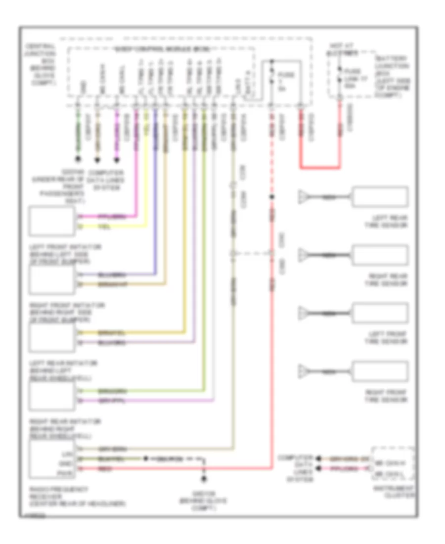
WARNING SYSTEMS
Warning Systems Wiring Diagram for Land Rover Discovery 2 2014
List of elements for Warning Systems Wiring Diagram for Land Rover Discovery 2 2014:
- Batt a
- Battery junction box (left side of engine compt)
- Body control module (bcm)
- C1bb03g
- C1bp01d
- C1bp01e
- C23w
- C23x
- C2bp01a
- C2bp01b
- C39c
- C39d
- C3bp01f
- C3bp01g
- Central junction box (behind glove compt)
- Computer data lines system
- Fl tpms 1+
- Fl tpms 1-
- Fr tpms 2+
- Fr tpms 2-
- Fuse 5a
- Fuse link 17 60a
- G3d140 (under rear of front passenger's seat)
- G6d139 (behind glove compt)
- Gnd
- Hot at all times
- Instrument cluster
- Left front initiator (behind left side of front bumper)
- Left front tire sensor
- Left rear initiator (behind left rear wheelwell)
- Left rear tire sensor
- Lin
- Lin 0
- Ms can h
- Ms can l
- Nca
- Pwr
- Radio frequency receiver (center rear of headliner)
- Red
- Right front initiator (behind right side of front bumper)
- Right front tire sensor
- Right rear initiator (behind right rear wheelwell)
- Right rear tire sensor
- Rl tpms 4+
- Rl tpms 4-
- Rr tpms 3+
- Rr tpms 3-
 English