WARNING SYSTEMS
Warning System Wiring Diagrams for Lexus GS 400 1998
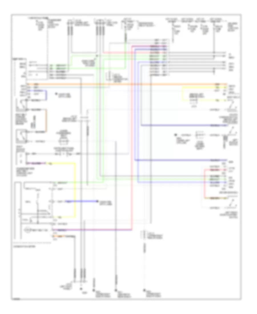
List of elements for Warning System Wiring Diagrams for Lexus GS 400 1998:
- (1998) (1999 & 2000)
- (behind left side of dash)
- (under passenger's seat) j/c 24
- Acc
- Bdr
- Becu
- Body ecu 1
- Body ecu 2
- Bsub
- C p u
- C12
- C13
- Combination meter
- Computer data lines
- Cpub
- Cty
- Ctye
- D fr door fuse 20a
- D22
- D23
- D24
- Dbkl
- Driver door ecu
- Driver's side junction block
- Ecu-ig fuse 15a
- Engine room relay block 1
- F11
- F13
- G200
- G201 (upper right side of dash)
- G311 (center of rear shelf)
- G904 (under left c-pillar)
- Gauge fuse 10a
- Gnd
- Gsw
- Gswo
- H10
- H11
- Hot at all times
- Hot in acc or run
- Hot in run or start
- I6 (dash harn, right side of dash)
- Instrument panel junction block
- J/c 10 (behind left side of dash)
- J/c 13 (behind combination meter)
- J/c 15 (upper left side of dash)
- J/c 17 (upper right end of dash)
- J/c 23 (under driver's seat)
- J/c 6 (left kick panel)
- J/c 7 (left kick panel)
- J/c 9
- Ksw
- Left buckle switch
- Left front door courtesy switch
- Mpx-b fuse 10a
- Mpx1
- Mpx2
- P fr door fuse 20a
- Passenger side junction block
- Passenger side seat belt warning light (in clock)
- Pbkl
- Radio fuse 10a
- Right buckle switch
- Seat belt ind
- Seat belt warning occupant detection sensor
- Sig
- Unlock warning switch (behind left side of dash)
 English