WARNING SYSTEMS
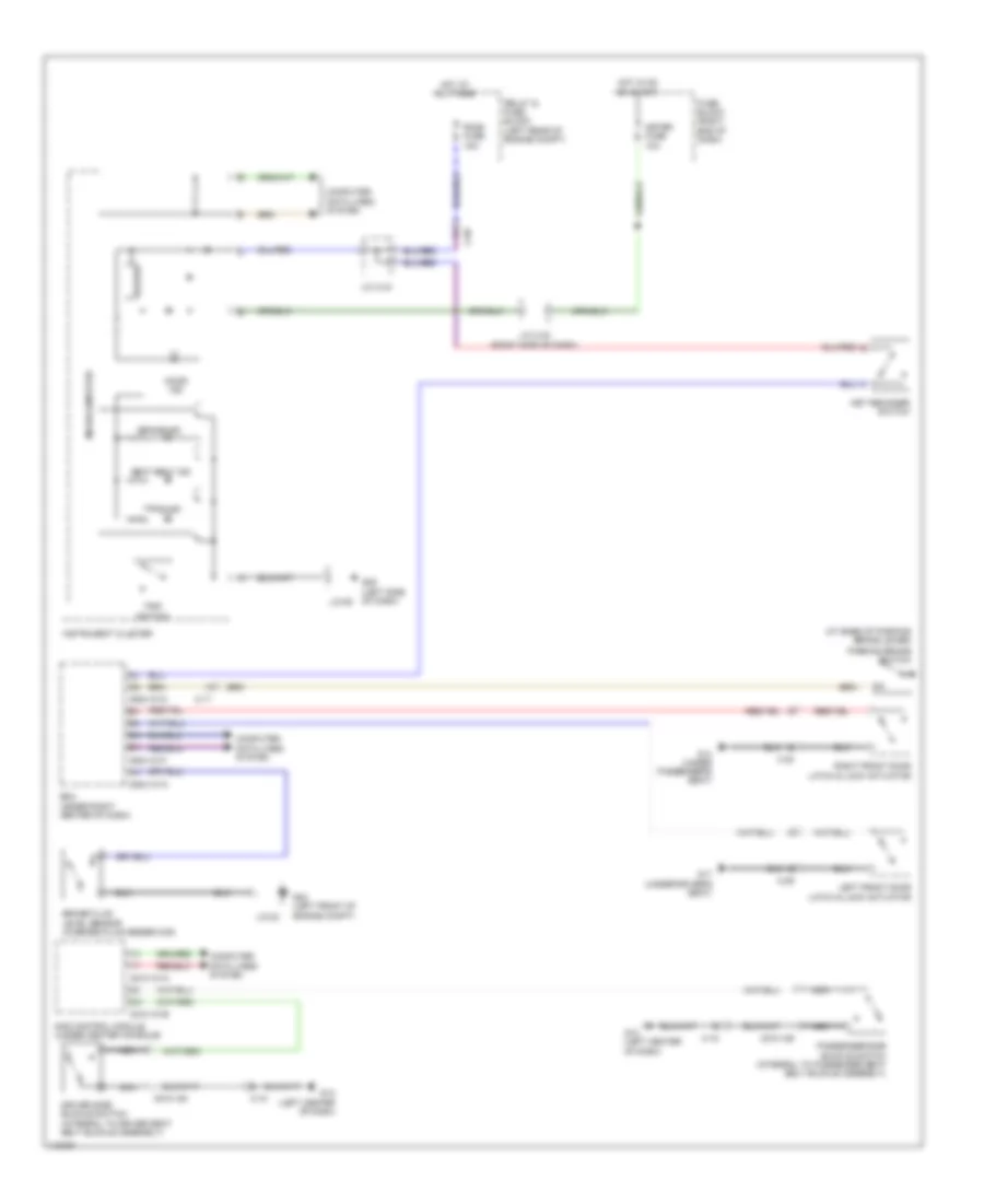
Warning Systems Wiring Diagram for Mazda 5 Grand Touring 2013
List of elements for Warning Systems Wiring Diagram for Mazda 5 Grand Touring 2013:
- (at base of parking brake lever)
- 0810-101a
- 0810-101b
- 0810-125
- 0810-126
- 0940-101a
- 0940-101c
- 0940-101f
- Bcm (under right center of dash)
- Brake fluid level sensor (in brake fluid reservoir)
- Brake ind
- Buzzer
- C-05
- C-17
- C-18
- C-29
- C-30
- Computer data lines system
- Door ind
- Driver side buckle switch (integral to driver seat belt buckle assembly)
- Fuse block (right end of dash)
- G02 (left front of engine compt)
- G09 (left side of dash)
- G12 (left center of dash)
- G14 (under passenger's seat)
- G17 (under driver's seat)
- Hot at all times
- Hot in on or start
- Instrument cluster
- J/c c-42 (right side of dash)
- J/c c-44
- J/c-02
- J/c-09
- Key reminder switch
- Left front door latch & lock actuator
- Meter fuse 10a
- Microcomputer
- Nca
- Parking brake switch
- Passenger side buckle switch (integral to passenger seat belt buckle assembly)
- Relay & fuse block (left rear of engine compt)
- Right front door latch & lock actuator
- Room fuse 15a
- Sas control module (under center console)
- Seat belt ind
- Tpms ind
- Trip switch
 English