WARNING SYSTEMS
Seat Belt Warning Wiring Diagram for Mercedes-Benz GL350 2012

List of elements for Seat Belt Warning Wiring Diagram for Mercedes-Benz GL350 2012:
- Audible turn signal ind
- Battery compartment prefuse box (behind right front seat)
- Bbv hr
- Bbv vr
- Brake fluid & parking brake warning lamp
- Brake fluid indicator switch (on brake fluid reservoir)
- C88
- Can b h
- Can b l
- Can-b h
- Can-b l
- Can-c h
- Can-c l
- Circuit 31 left footwell voltage distributor connector 1
- Circuit 31 right wheelhouse luggage compartment voltage distributor connector
- Computer data lines system
- Driver door cl motor/ switch (rear of driver door)
- Driver seat belt buckle & seat belt warning switch (in driver's seat belt buckle assembly)
- F zv df
- Front sam control unit (under front passenger seat)
- Fuse 7.5a
- Fuse 70a
- H6 x25/2-c2
- Hot at all times
- Hot w/ circuit 15 relay energized
- Instrument cluster
- Load compartment fuse & relay box (right side of cargo area)
- Multi-function display
- Nca
- Parking brake indicator switch (under left end of dash)
- Rear sam control module (right rear of cargo area)
- Red
- Restraints system control module (under center console)
- Right front brake pad contact sensor (on right front brake assembly)
- Right rear brake pad contact sensor (on right rear brake assembly)
- Seat belt warning lamp
- W15/1 (right front footwell)
- W15/2 (left front footwell)
- W2 (right side of engine compt)
- W26 (under front of center console)
- W29/2 (behind right kick panel)
- W7 (at right "d" pillar)
- Warning buzzer
- X25/2-c1
- X35/1
- X55/3-c2
- X55/3-c2b
- X62/33-a
- X62/36
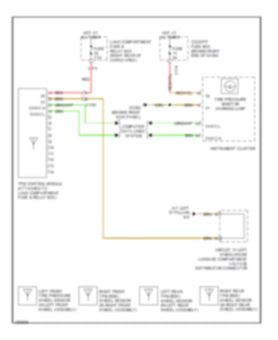
Tire Pressure Monitoring Wiring Diagram for Mercedes-Benz GL350 2012
List of elements for Tire Pressure Monitoring Wiring Diagram for Mercedes-Benz GL350 2012:
- (at left "d" pillar) w6
- C11a
- Can c h
- Can c l
- Can-c h
- Can-c l
- Circuit 31 left wheelhouse luggage compartment voltage distributor connector
- Cockpit fuse box (behind right end of dash)
- Computer data lines system
- Fuse 5a
- Fuse 7.5a
- Hot at all times
- Instrument cluster
- Left front tire pressure wheel sensor (in left front wheel assembly)
- Left rear tpm (rdk) wheel sensor (in left rear wheel assembly)
- Load compartment fuse & relay box (right rear of cargo area)
- Red
- Right front tpm (rdk) wheel sensor (in right front wheel assembly)
- Right rear tpm (rdk) wheel sensor (in right rear wheel assembly)
- Tire pressure monitor warning lamp
- Tpm control module (attached to load compartment fuse & relay box)
- W29/2 (behind right kick panel)
- X1/60