WARNING SYSTEMS
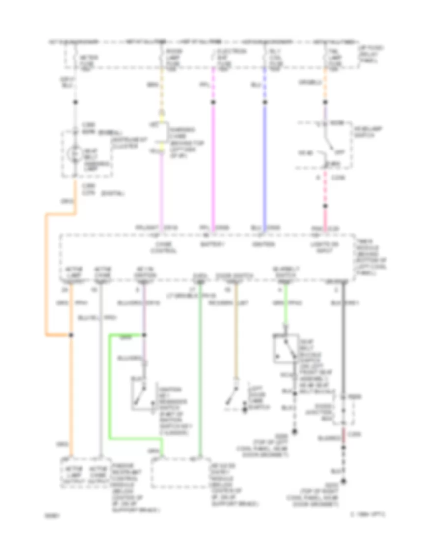
Warning System Wiring Diagrams for Mercury Villager GS 1994
List of elements for Warning System Wiring Diagrams for Mercury Villager GS 1994:
- (behind top left side of i/p)
- (digital)
- 1994 vftc c
- Active chime input
- Active chime output
- Active lamp output
- Battery
- C256
- C258
- C268 c276
- Chime control
- Data line
- Diode junction box
- Door switch input
- Electron bat fuse 10a
- G200 (top of left cowl panel, near door grommet)
- G203 (top of right cowl panel, near door grommet)
- Ground
- Head
- Headlamp switch
- Hot at all times
- Hot in run or start
- I/p fuse/ relay panel
- Ignition
- Ignition key reminder switch (part of ignition switch key cylinder)
- Instrument cluster
- Key in ignition input
- Keyless entry module (below center of i/p, on i/p support brace)
- Left door jamb switch
- Lights on input
- Meter fuse 10a
- Nca
- Off
- Park
- Passive restraint control module (below center of i/p, on i/p support brace)
- Ph16
- Pnk ic20
- Rly coil fuse 10a
- Room lamp fuse 15a
- Seat belt buckle switch (on left front seat assembly, near seat belt buckle
- Seat belt warning lamp
- Seatbelt switch input
- Tail lamp fuse 15a
- Timer module (behind bottom of left cowl panel)
- Warning chime
 English