WARNING SYSTEMS
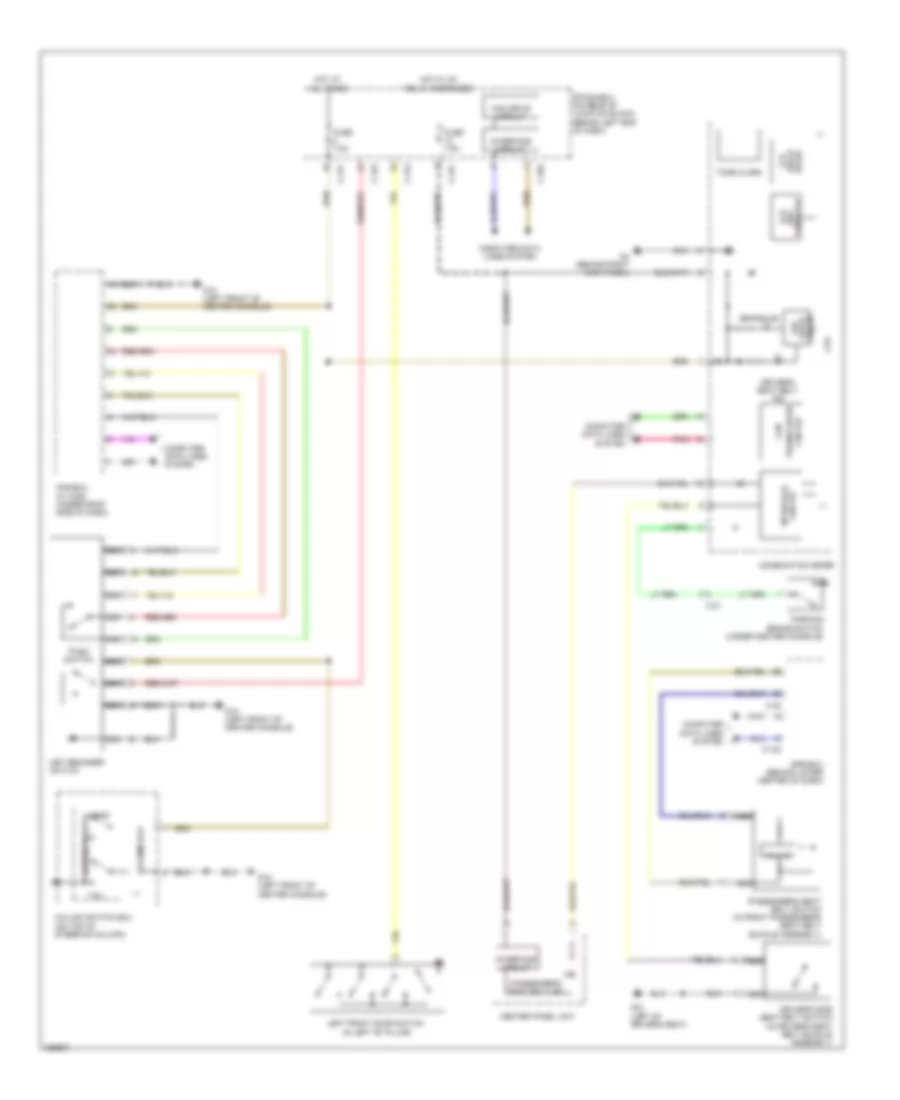
Chime Wiring Diagram, Evolution for Mitsubishi Lancer Ralliart 2010

List of elements for Chime Wiring Diagram, Evolution for Mitsubishi Lancer Ralliart 2010:
- (each lcd
- (key reminder)
- Brake ind
- C-23
- C-301
- C-313
- C-315
- C-317
- C-36
- C-37
- C-41
- Can drive circuit
- Center panel unit
- Circuit interface
- Circuit transceiver can
- Column ecu
- Column switch (on top of steering column)
- Combination meter
- Computer data lines system
- Cpu
- Door)
- Drive circuit
- Driver's seat belt ind
- Driver's side seat belt switch (in driver's seat belt buckle assembly)
- Etacs-ecu (on rear of junction block, behind left end of dash)
- Fuse 7.5a
- G18 (left front engine compt)
- G20 (left side engine compt)
- G4 (behind right kick panel)
- Hall ic
- Head
- Hot at all times
- Hot w/ ignition 1 relay energized
- Interface circuit
- Key reminder switch
- Kos ecu (w/ kos) (under right side of dash)
- Lcd
- Led
- Left front door switch (in left "b" pillar)
- Lighting switch
- Nca
- Parking brake switch (under center console)
- Passenger's seat belt ind
- Passenger's seat belt switch (in front passenger's seat belt buckle assembly)
- Pnk
- Push switch
- Srs ecu (behind lower center of dash)
- Tail
- Tone alarm
Chime Wiring Diagram, Except Evolution for Mitsubishi Lancer Ralliart 2010
List of elements for Chime Wiring Diagram, Except Evolution for Mitsubishi Lancer Ralliart 2010:
- (each lcd
- Brake ind
- C-122
- C-21
- C-30
- C-301
- C-313
- C-315
- C-317
- Can
- Can drive circuit
- Center panel unit
- Circuit interface
- Circuit transceiver
- Column ecu
- Column switch ecu (on top of steering column)
- Combination meter
- Computer data lines system
- Cpu
- Door)
- Drive circuit
- Driver's seat belt ind
- Driver's side seat belt switch (in driver's seat belt buckle assembly)
- Etacs-ecu (on rear of junction block, behind left end of dash)
- Fuse 7.5a
- G12 (left of driver's seat)
- G15 (left front of center console)
- G4 (behind right kick panel)
- Hall ic
- Head
- Hot at all times
- Hot w/ ig1 relay energized
- Interface circuit
- Key reminder switch
- Kos-ecu (w/ kos) (under right side of dash)
- Led
- Left front door switch (in left "b" pillar)
- Lighting switch
- Nca
- Parking brake switch (under center console)
- Passenger's seat belt ind
- Passenger's seat belt switch (in front passenger's seat belt buckle assembly)
- Pnk
- Push switch
- Reminder) (key lcd
- Srs-ecu (behind lower center of dash)
- Tail
- Tone alarm
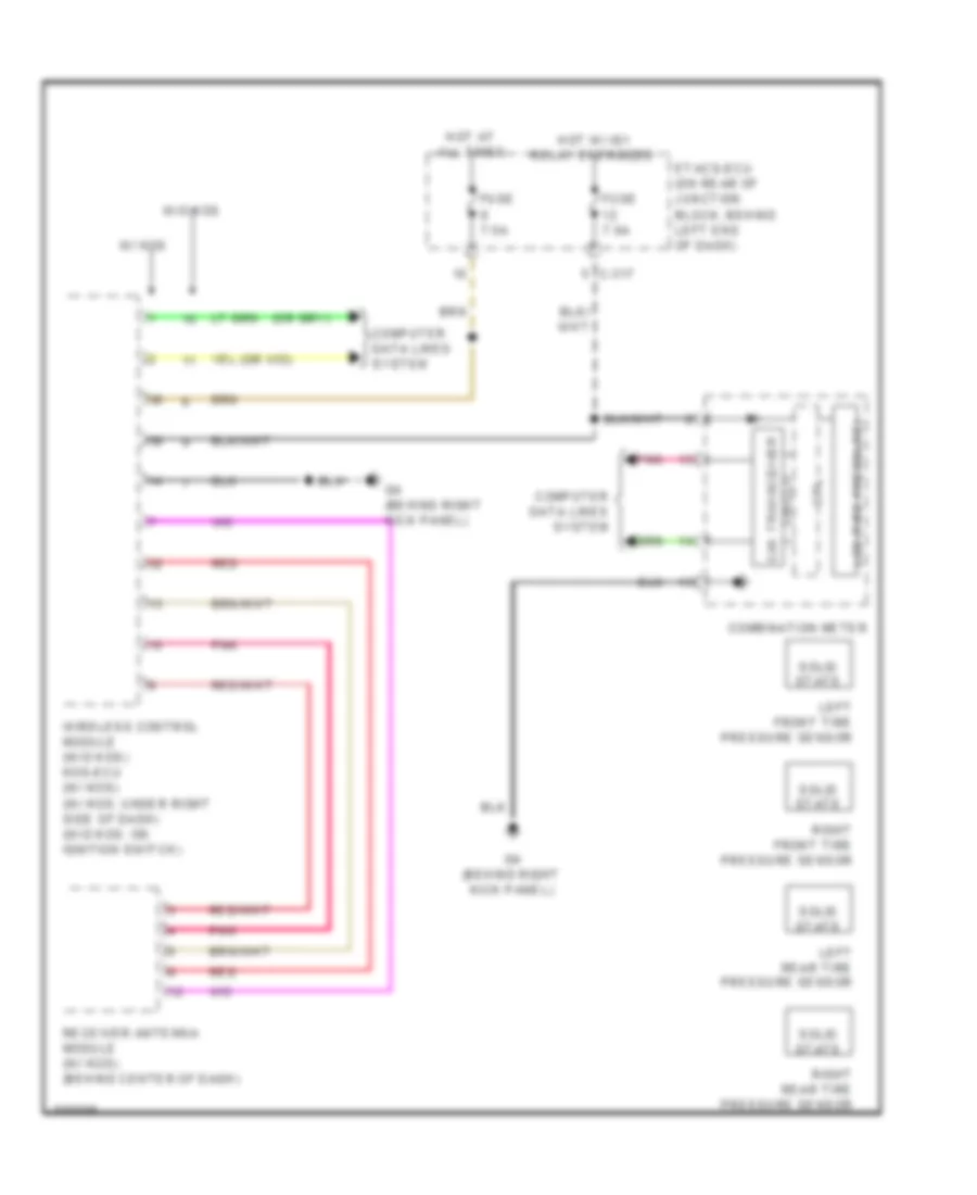
Tire Pressure Monitoring Wiring Diagram, Evolution for Mitsubishi Lancer Ralliart 2010
List of elements for Tire Pressure Monitoring Wiring Diagram, Evolution for Mitsubishi Lancer Ralliart 2010:
- (w/o kos) (w/ kos)
- C-301
- C-317
- C-41
- Can drive circuit
- Can transceiver
- Circuit
- Combination meter
- Computer data lines system
- Cpu
- Etacs-ecu (on rear of junction block, behind left end of dash)
- Fuse 7.5a
- G4 (behind right kick panel)
- G6 (behind center of dash)
- Hot at all times
- Hot w/ ignition 1 relay energized
- Interface circuit
- Joint connector 6
- Kos-ecu (w/ kos) (under right side of dash)
- Lcd (tire pressure)
- Left front tire pressure sensor
- Left rear tire pressure sensor
- Nca
- Pnk
- Receiver
- Receiver antenna assembly
- Red
- Right front tire pressure sensor
- Right rear tire pressure sensor
- Solid state
- W/ kos
- W/o kos
- Wireless control module (w/o kos) (on ignition switch)
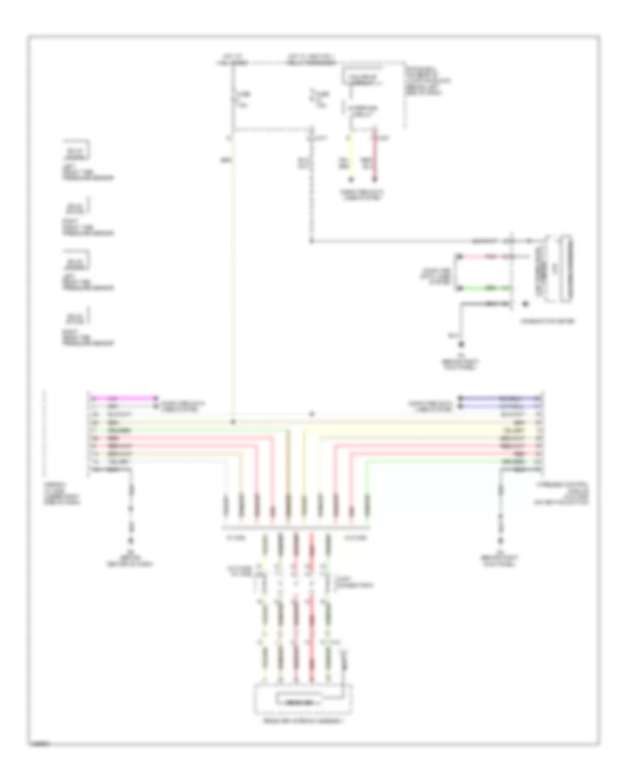
Tire Pressure Monitoring Wiring Diagram, Except Evolution for Mitsubishi Lancer Ralliart 2010
List of elements for Tire Pressure Monitoring Wiring Diagram, Except Evolution for Mitsubishi Lancer Ralliart 2010:
- C-317
- Can transceiver
- Circuit
- Combination meter
- Computer data lines system
- Cpu
- Etacs-ecu (on rear of junction block, behind left end of dash)
- Fuse 7.5a
- G4 (behind right kick panel)
- Hot at all times
- Hot w/ ig1 relay energized
- Lcd (tire pressure)
- Left front tire pressure sensor
- Left rear tire pressure sensor
- Pnk
- Receiver antenna module (w/ kos) (behind center of dash)
- Red
- Right front tire pressure sensor
- Right rear tire pressure sensor
- Solid state
- W/ kos
- W/o kos
- Wireless control module (w/o kos) kos-ecu (w/ kos) (w/ kos: under right side of dash) (w/o kos: on ignition switch)