WARNING SYSTEMS
Chime Wiring Diagram for Mitsubishi Montero Limited 2004

List of elements for Chime Wiring Diagram for Mitsubishi Montero Limited 2004:
- (lower left side of dash, right of steering column)
- Column ecu
- Column switch (at top of steering column)
- Combination meter
- D03
- D04
- D209
- D210
- D217
- D220
- D221
- D222
- D224
- D32
- Data link connector
- Dedicated fuse 18 15a
- Door ind
- Engine compartment relay box (left side of engine compt)
- Etacs ecu
- G10 (under left front kick panel)
- G7 (under dash, on driver side center reinforcement)
- Headlights system
- Hot at all times
- Hot in run or start
- Interior lights system
- Joint connector 6 (behind left side of dash)
- Joint connector 8 (behind left side of dash)
- Junction block (behind lower left side of dash)
- Key reminder switch
- Left front door switch
- Multi- purpose fuse 6 10a
- Nca
- Pnk
- Seat belt ind
- Seat belt switch
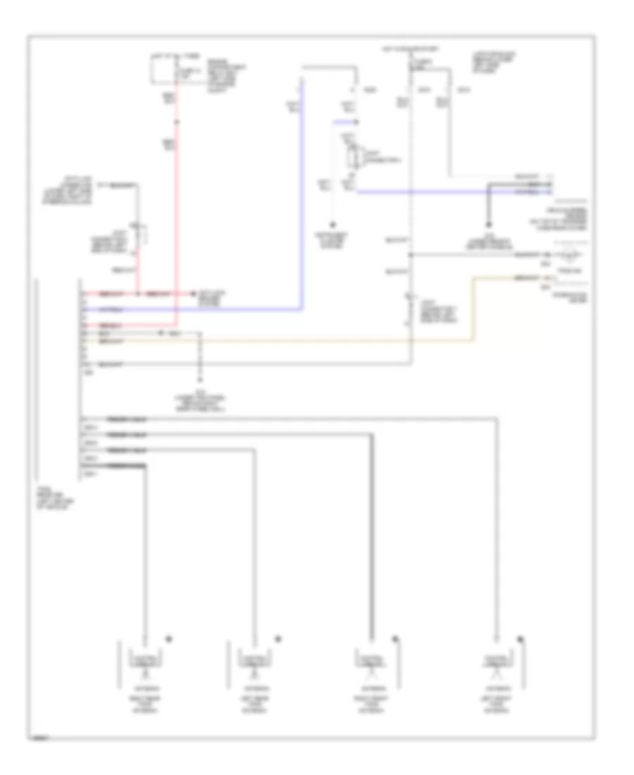
Tire Pressure Monitoring Wiring Diagram for Mitsubishi Montero Limited 2004
List of elements for Tire Pressure Monitoring Wiring Diagram for Mitsubishi Montero Limited 2004:
- Antenna
- Anti-lock brakes system
- Combination meter
- Connector 4
- Connector 5 (behind left end of dash)
- Connector 7 (behind left side of dash)
- Control circuit
- D03
- D04
- D210
- D212
- D220
- Data link connector (lower left side of dash, right of steering column)
- Engine compartment relay box (left side of engine compt)
- Feeder cable
- Fuse 18 15a
- Fuse 6 10a
- G15 (under trim panel, behind right rear wheelwell)
- G16 (under rear of center console)
- G28
- G28-1
- G28-3
- G28-4
- G28-5
- Hot at all times
- Hot in run or start
- Instrument cluster system
- Joint
- Junction block (behind lower left side of dash)
- Left front tpms antenna
- Left rear tpms antenna
- Right front tpms antenna
- Right rear tpms antenna
- Tpms ind
- Tpms receiver (left center of vehicle)
- Vehicle speed sensor (on top of transfer case rear cover)