WARNING SYSTEMS
Chime Wiring Diagram for Nissan Maxima SV 2013

List of elements for Chime Wiring Diagram for Nissan Maxima SV 2013:
- (behind right side of dash) m57
- (w/ information display) unified meter control unit
- 10j
- 11p
- 12m
- 24g
- 24j
- 57g
- Air bag diagnosis sensor unit (under rear of center console)
- B1 m6
- B12
- B201
- B7 (under driver's seat)
- Bat (f/l)
- Bat bcm fuse
- Bcm (body control module) (behind instrument cluster)
- Brake ind
- Buzzer
- Can-h
- Can-l
- Card sw1
- Combination meter
- Combination switch (lighting & turn signal switch)
- Computer data lines system
- Dr door sw
- E30
- Fob in sw 1
- Fuse & fusible link box (left front of engine compt)
- Fuse 10a
- Fuse block (j/b) (lower left side of dash)
- Fusible link h 40a
- Gnd
- Gnd 1
- Hot at all times
- Hot in on or start
- Input 1
- Input 2
- Input 3
- Input 4
- Input 5
- Intelligent key warning buzzer (behind left end of dash)
- Joint connector b04 (left side of luggage compt)
- K-line seat belt reminder m35
- Key slot
- Left front door switch (left "b" pillar)
- Left seat belt buckle switch (under driver's seat)
- Lh buckle sw input b9
- M1 e30
- M16
- M17
- M18
- M19
- M21
- M24
- M57 (behind right side of dash)
- M6 b1
- M79 (left center of dash)
- Navigation & sound systems
- Output 1
- Output 2
- Output 3
- Output 4
- Output 5
- Parking brake switch (on brake pedal bracket)
- Pnk
- Red
- Seat belt ind
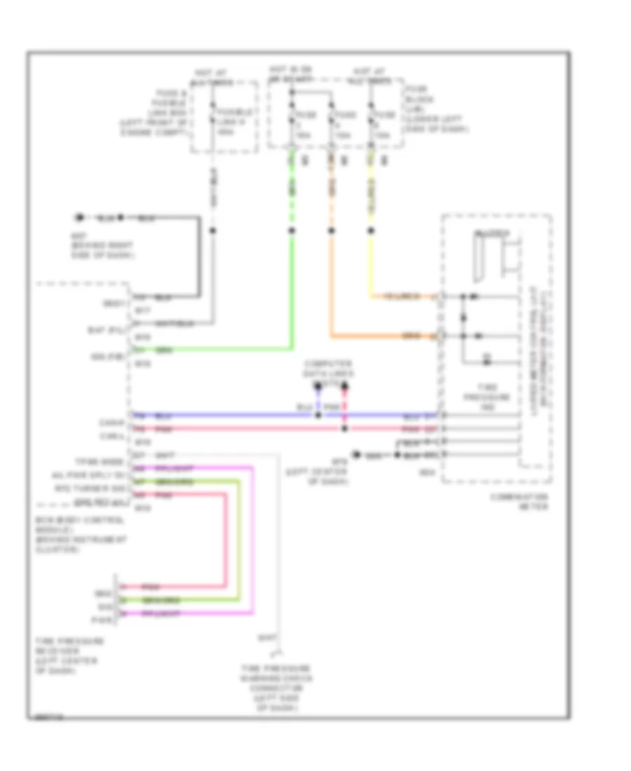
Tire Pressure Monitoring Wiring Diagram for Nissan Maxima SV 2013
List of elements for Tire Pressure Monitoring Wiring Diagram for Nissan Maxima SV 2013:
- (w/ information display) unified meter control unit
- 12m
- A/l pwr sply 5v
- Bat (f/l)
- Bcm (body control module) (behind instrument cluster)
- Buzzer
- Can-h
- Can-l
- Combination meter
- Computer data lines system
- Fuse & fusible link box (left front of engine compt)
- Fuse 10a
- Fuse block (j/b) (lower left side of dash)
- Fusible link h 40a
- Gnd
- Gnd rf2 a/l
- Gnd1
- Hot at all times
- Hot in on or start
- Ign (f/b)
- M16
- M17
- M18
- M19
- M24
- M57 (behind right side of dash)
- M79 (left center of dash)
- Pnk
- Pwr
- Rf2 turner sig
- Sig
- Tire pressure ind
- Tire pressure receiver (left center of dash)
- Tire pressure warning check connector (left side of dash)
- Tpms mode