WARNING SYSTEMS
Buzzer Wiring Diagram for Nissan Murano SE 2004

List of elements for Buzzer Wiring Diagram for Nissan Murano SE 2004:
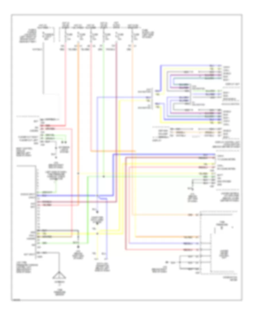
Tire Pressure Monitoring Wiring Diagram for Nissan Murano SE 2004
List of elements for Tire Pressure Monitoring Wiring Diagram for Nissan Murano SE 2004: