WARNING SYSTEMS
Chime Wiring Diagram for Nissan NV200 Taxi 2014

List of elements for Chime Wiring Diagram for Nissan NV200 Taxi 2014:
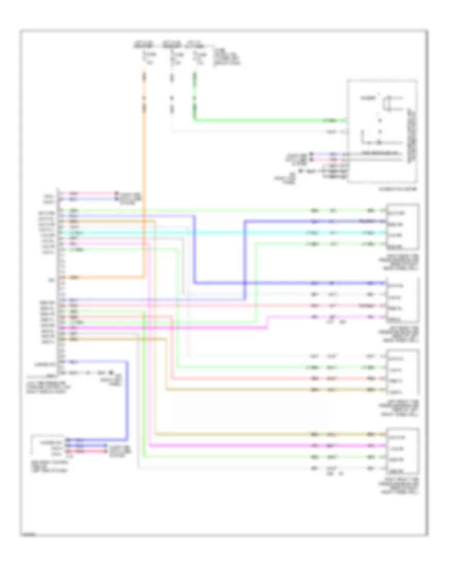
Tire Pressure Monitoring Wiring Diagram for Nissan NV200 Taxi 2014
List of elements for Tire Pressure Monitoring Wiring Diagram for Nissan NV200 Taxi 2014: