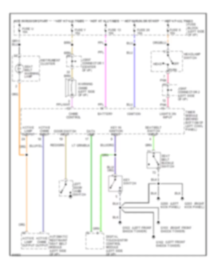
WARNING SYSTEMS
Warning System Wiring Diagrams for Nissan Quest GXE 1995
List of elements for Warning System Wiring Diagrams for Nissan Quest GXE 1995:
- (left
- (left front
- (right
- (right front
- Active chime input
- Active chime output
- Active lamp output
- Automatic restraint seat belt module (left side of i/p)
- Battery
- Chime (left side of i/p)
- Chime control
- Data line
- Digital touch entry control module (left side of i/p)
- Door switch input
- Fuse 13 10a
- Fuse 20 10a
- Fuse block (left side of i/p)
- Fuse s 15a
- Fuse u 10a
- Fuse y 15a
- G102 shock tower)
- G103 shock tower)
- G200 kick panel)
- G203 kick panel)
- Head
- Headlamp switch
- Hot at all times
- Hot in run or start
- Ignition
- Instrument cluster
- Joint connector 1 (center of i/p)
- Joint connector 2 (left side of i/p)
- Key in ignition input
- Key switch
- Left door jamb switch
- Lights on input
- Off
- Park
- Pnk
- Seat belt buckle switch
- Seat belt warning lamp
- Seatbelt switch input
- Timer module (behind bottom of left cowl panel)
- Warning
 English