WARNING SYSTEMS
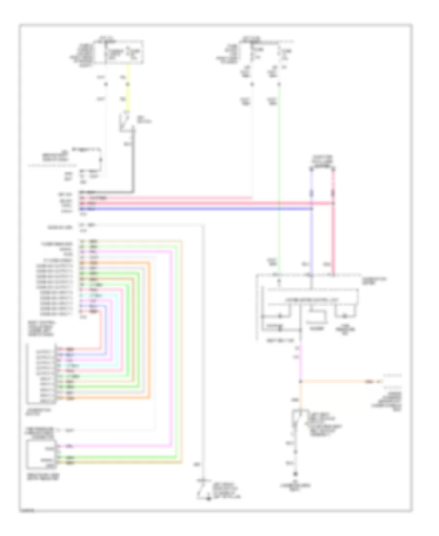
Warning Systems Wiring Diagram for Nissan Xterra SE 2005
List of elements for Warning Systems Wiring Diagram for Nissan Xterra SE 2005:
- 15p
- Air bag diagnosis sensor unit (under console box)
- B7 (under driver's seat)
- Bat
- Body control module (bcm) (under left side of dash)
- Buzzer
- Can-h
- Can-l
- Combi sw input 1
- Combi sw input 2
- Combi sw input 3
- Combi sw input 4
- Combi sw input 5
- Combi sw output 1
- Combi sw output 2
- Combi sw output 3
- Combi sw output 4
- Combi sw output 5
- Combination
- Combination meter
- Computer data lines system
- Door ind
- Door sw (dr)
- Fuse & fusible link box (right rear of engine compt)
- Fuse 10a
- Fuse block (j/b) (right side of dash)
- Fusible link g 50a
- Gnd
- Hot at all times
- Hot in on or start
- Ign sw
- Input 1
- Input 2
- Input 3
- Input 4
- Input 5
- Key sw
- Key switch
- Left front door switch (at base of left "b" pillar)
- Left seat belt buckle switch (in driver's seat belt buckle assembly)
- M18
- M19
- M20
- M61 (behind right side of dash)
- Output 1
- Output 2
- Output 3
- Output 4
- Output 5
- P/ warn check
- Pnk
- Pwr
- Red
- Remote keyless entry receiver
- Seat belt ind
- Signal
- Switch
- Tire pressure ind
- Tire pressure warning check connector
- Tuner sens gnd
- Unified meter control unit
 English