WARNING SYSTEMS
Chime Wiring Diagram for Pontiac Vibe 2010

List of elements for Chime Wiring Diagram for Pontiac Vibe 2010:
- Anti-theft system
- Auto
- Body control module
- Computer data lines system
- Data bus +
- Data bus -
- Daytime running lights (drl) module (left side of dash)
- Driver door jamb switch (left "b" pillar)
- Driver seat belt buckle (driver's seat belt buckle assembly)
- Driver seat belt switch
- Ecu-ig 2 fuse 7 10a
- G200 (left kick panel)
- Head
- Headlights system
- Hot w/ ig 1 relay energized
- Hot w/ ign 2 pcb relay energized
- I/p fuse block (left end of dash)
- Ign
- Ignition key alarm switch (at ignition switch)
- Ind
- Inflatable restraint sensing & diagnostic module (sdm) (under center console)
- Instrument panel cluster (ipc)
- J219
- J220 (instrument panel harness)
- Left seat belt sw sig
- Logic
- Low ref
- Meter fuse 31 7.5a
- Nca
- Off
- Park
- Parking brake switch (under center console)
- Red
- Seat belt
- Seat belt ind
- Security indicator lamp
- Serial data (+)
- Serial data (-)
- Sir indicator
- Turn signal/ multi-function switch
- X12
- X13
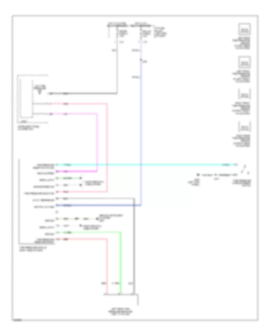
Tire Pressure Monitoring Wiring Diagram for Pontiac Vibe 2010
List of elements for Tire Pressure Monitoring Wiring Diagram for Pontiac Vibe 2010:
- (behind instrument cluster) g201
- 5-volt reference
- Computer data lines system
- Ecu-ig1 fuse 6 10a
- Engine speed sig
- G200 (left kick panel)
- Ground
- Hot w/ ig 1 relay energized
- Hot w/ ig 2 pcb relay energized
- I/p fuse block (left end of dash)
- Ignition voltage
- Instrument panel cluster (ipc)
- J203
- J219
- J231
- Left front tire pressure sensor (in left front valve stem)
- Left rear tire pressure receiver (left "c" pillar)
- Left rear tire pressure sensor (in left rear valve stem)
- Logic
- Low tire pressure ind
- Meter fuse 31 7.5a
- Pnk
- Red
- Right front tire pressure sensor (in right front valve stem)
- Right rear tire pressure sensor (in right rear valve stem)
- Serial data
- Solid state
- Tire pressure indicator
- Tire pressure module (right side of dash)
- Tire pressure receiver signal
- Tire pressure reset switch sig
- Tire pressure warning reset switch
- Vehicle speed
- X12
- X13