WARNING SYSTEMS
Chime Wiring Diagram for Subaru Forester XT Premium 2012

List of elements for Chime Wiring Diagram for Subaru Forester XT Premium 2012:
- B186
- B279
- B280
- B281
- B38
- B52
- B99
- Body integrated unit (behind center of dash)
- Buzzer
- Can transeiver & receiver
- Clock
- Combination meter
- Computer data lines system
- Door warning light ind
- Drive circuit
- Fuse & relay box (f/b) (left kick panel)
- Fuse 10a
- Fuse 15a
- Fuse 7.5a
- Gb-9 (behind left rear quarterpanel)
- Hot at all times
- Hot in on or start
- Hot w/ ig2 relay energized
- I/f
- I102
- I84
- Key warning switch (left side of dash)
- Left front door switch (left "b" pillar)
- Light ind warning seat belt
- Main fuse box (m/b) (left side of engine compt)
- Micro computer
- Passenger's seat belt warning light ind
- Pnk
- Power distribution system
- R167
- R168
- Red
- Remote engine start control module (left side of dash)
- Seat belt switch (driver's seat belt buckle)
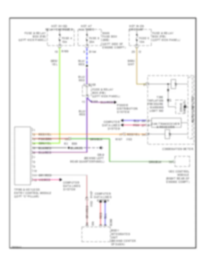
Tire Pressure Monitoring Wiring Diagram for Subaru Forester XT Premium 2012
List of elements for Tire Pressure Monitoring Wiring Diagram for Subaru Forester XT Premium 2012:
- (left side of engine compt)
- B144
- B158
- B280
- B99
- Body integrated unit (behind center of dash)
- Can transceiver & receiver
- Combination meter
- Computer data lines system
- Drive circuit
- Fuse & relay box (f/b) (left kick panel)
- Fuse 4 10a
- Fuse 5 10a
- Fuse 8 20a
- Gb-9 (behind left rear quarterpanel)
- Hot at all times
- Hot in on or start
- Hot w/ ig2 relay energized
- I/f
- I102
- I84
- Main fuse box (m/b)
- Micro computer
- Pnk
- Power distribution system
- R167
- R167 i102
- R168
- Red
- Tire inflation pressure warning light ind
- Tpms & keyless entry control module (left "c" pillar)
- Vdc control module (right rear of engine compt)