
WARNING SYSTEMS
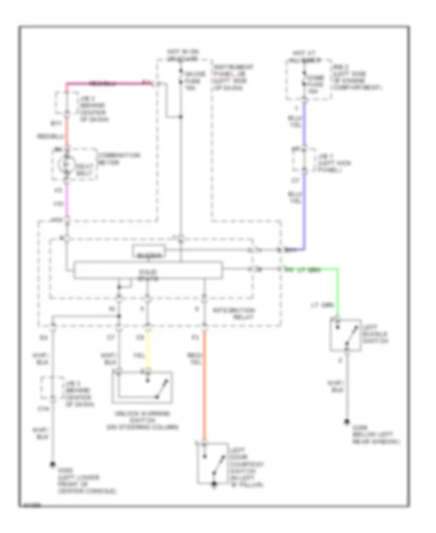
Warning System Wiring Diagrams for Toyota Celica GT 1997
List of elements for Warning System Wiring Diagrams for Toyota Celica GT 1997:
AIR CONDITIONINGCOMPUTER DATA LINESCOOLING FANCRUISE CONTROLDEFOGGERSENGINE PERFORMANCEEXTERIOR LIGHTSGROUND DISTRIBUTIONHEADLIGHTSHORNINSTRUMENT CLUSTERINTERIOR LIGHTSPASSIVE RESTRAINTSPOWER ANTENNAPOWER DISTRIBUTIONPOWER DOOR LOCKSPOWER MIRRORSPOWER TOP/SUNROOFPOWER WINDOWSRADIOSHIFT INTERLOCKSSTARTING/CHARGINGSUPPLEMENTAL RESTRAINTSTRANSMISSIONWARNING SYSTEMSWIPER/WASHER