WIPER/WASHER
Wiper/Washer Wiring Diagram (1 of 2) for Chevrolet Corvette Grand Sport 2013

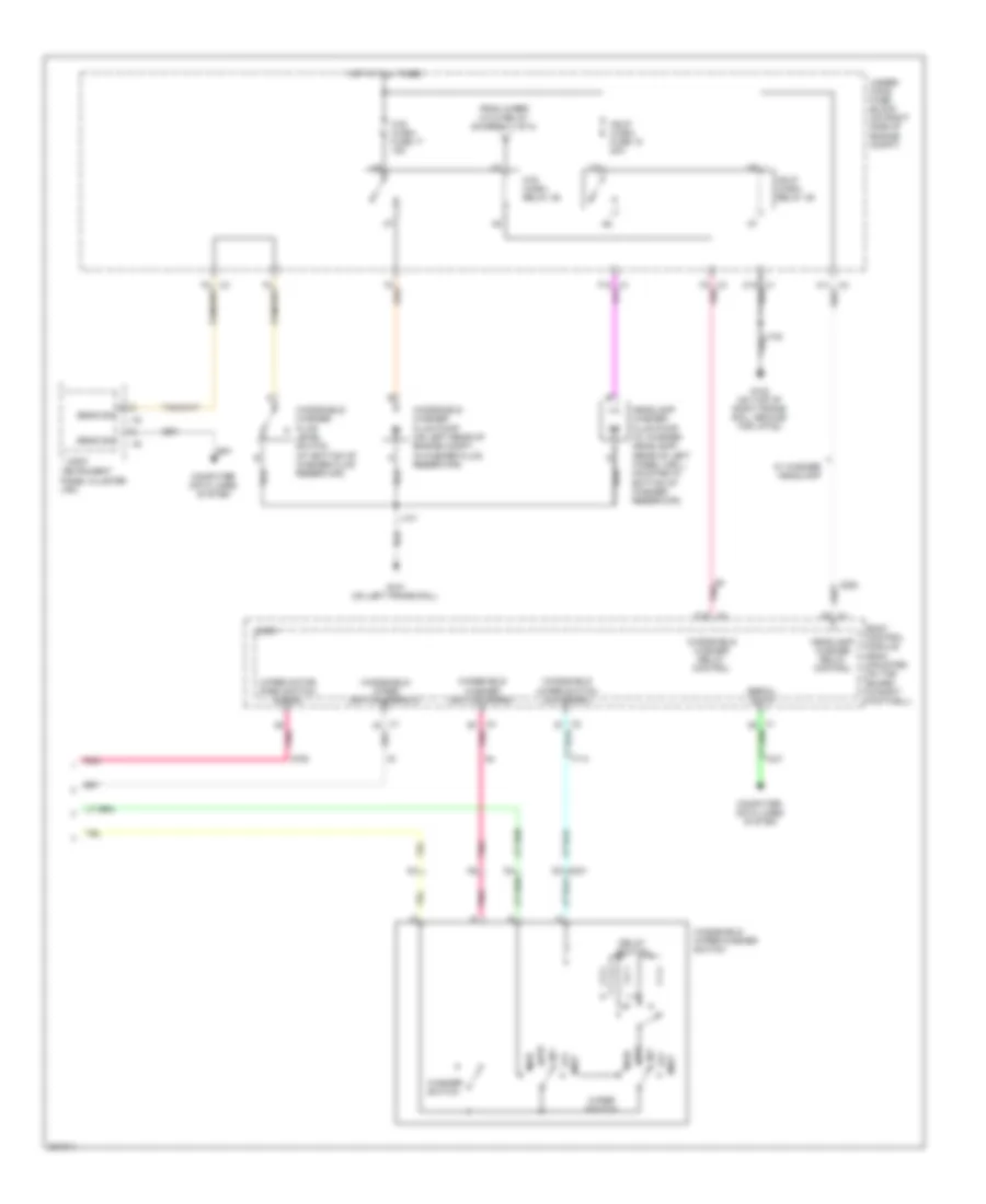
List of elements for Wiper/Washer Wiring Diagram (1 of 2) for Chevrolet Corvette Grand Sport 2013:
- (not used)
- Accessory voltage signal
- Body control module (mounted on toe board, in right footwell)
- Diode 1
- Diode 2
- F16
- F19
- G102 (on top of right frame rail, ground for jp102)
- G16
- G19
- G201 (at base of left "a" pillar)
- G202 (at base of right "a" pillar)
- Gnd
- High
- Hot at all times
- Htd seat/ wpr rly fuse 10a
- I/p fuse block (in right front footwell, mounted to toe board)
- J102
- J216
- K10
- K14
- K15
- K18
- K19
- L10
- L18
- Logic
- Low
- M10
- M11
- M14
- M15
- M18
- M19
- Park switch
- Pnk
- Run crank relay
- Run/ crank relay control
- To w/s wash relay 36 (diagram 2 of 2)
- Under- hood fuse block (on right side of engine compt)
- Windshield wiper motor (on left side of firewall)
- Wiper diode
- Wiper fuse 4 30a
- Wiper hi/lo relay 41
- Wiper on/off relay 45
- Wiper run/acc relay 42
- Wpr dwell fuse 10a
- Wpr/ washer fuse 10a
- X3 c3
- X3 d1
- X3 e11
Wiper/Washer Wiring Diagram (2 of 2) for Chevrolet Corvette Grand Sport 2013
List of elements for Wiper/Washer Wiring Diagram (2 of 2) for Chevrolet Corvette Grand Sport 2013:
- Body control module (bcm) (mounted on toe board, in right footwell)
- Computer data lines system
- Delay switch
- From wiper hi/lo relay (diagram 1 of 2)
- G101 (on left frame rail)
- G102 (on top of right frame rail, ground for jp102)
- Hdlp wash fuse 18 20a
- Hdlp wash relay 46
- Headlamp washer fluid pump (w/ washer headlamp) (rear of left wheel well, mounted in bottom of washer reservoir)
- Headlamp washer relay control
- High
- Hot at all times
- Instrument panel cluster (ipc)
- Int
- J101
- Logic
- Low
- Mist
- Off
- Pnk
- Pnk a8
- Pnk g
- Sens sig
- Serial data
- Under- hood fuse block (on right side of engine compt)
- W/ washer headlamp
- W/s wash fuse 17 15a
- W/s wash relay 36
- Washer switch
- Windshield washer fluid level switch (at bottom of washer fluid reservoir)
- Windshield washer fluid pump (on left rear of engine compt, in washer fluid reservoir)
- Windshield washer relay control
- Windshield washer switch signal
- Windshield wiper switch low signal
- Windshield wiper switch signal 2
- Windshield wiper/washer switch
- Wiper motor park switch signal
- Wiper switch
- X3 c12
- X3 f2 pnk
- X4 b1 pnk