AIR CONDITIONING
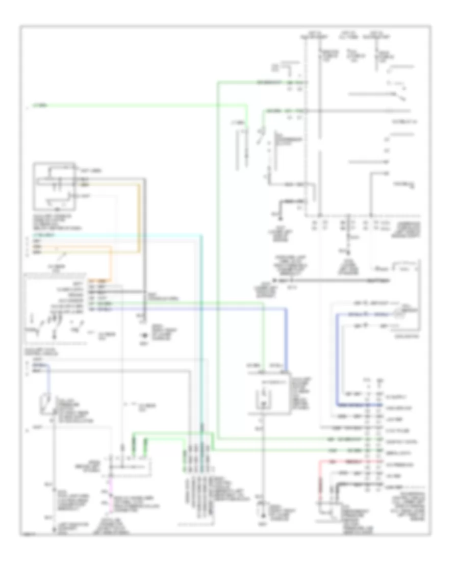
Automatic A/C Wiring Diagram, Short Wheel Base (1 of 2) for Buick Rainier 2004


List of elements for Automatic A/C Wiring Diagram, Short Wheel Base (1 of 2) for Buick Rainier 2004:
- (i/p harn, 15 cm from mode act breakout)
- (i/p harn, 15 cm from rec act breakout)
- 5v ref
- A/c comp status
- A/c low press sw
- A10
- A11
- A12
- Air temp door ctrl
- Air temp dr pos sig
- Air temperature actuator (left) (behind left center of dash)
- Air temperature actuator (right) (behind right center of dash)
- Ambient air temp sig
- Ambient air temperature sensor (on left center of radiator support)
- Ambient light
- Ambient light/ sunload sensor assembly (top center of dash)
- B10
- B11
- B12
- Battery
- Blower fuse 35 40a
- Blower motor
- Blower motor control module
- Blwr mtr spd ctrl
- Class 2
- Def door pos sig
- Defrost actuator (upper left center of dash)
- Defrost door ctrl
- G102 (left side of engine compartment)
- G201
- G302 (on lower left "b" pillar)
- Ground
- Hot at all times
- Hot in run
- Hvac control module
- Hvac i fuse 39 10a
- Hvac-b fuse 36 10a
- Ign 3
- Inside air temp ctrl
- Inside air temp sig
- Inside air temperature sensor (top of left "b" pillar, behind trim)
- Interior lights system
- Left sensor
- Low ref
- Low reference
- Lower left air temperature sensor (behind lower left of dash, on air duct)
- Lower right air temperature sensor (behind lower right of dash, on air duct)
- Lps dimming ctrl
- Lwr lt air temp sig
- Lwr rt air temp sig
- Mode actuator (upper left center of dash)
- Mode door ctrl
- Mode door pos sig
- Rear fuse block (below left rear seat)
- Recirc door cntrl
- Recirc dr pos sig
- Recirulation actuator (upper right side of dash)
- Red
- Right sensor
- S202 (i/p harn, 16.5 cm from strng col conn breakout)
- S211 (i/p harn, 16 cm from sp201)
- S216
- S217
- S271 (i/p harn, 14.5 cm from dash comp lamp breakout)
- S302 (5 cm from main harn breakout)
- Solid state
- Sp201 (right front of lower console)
- Sp201 (right frt of lower console)
- Tan
- Under- hood fuse block (left side of engine compt)
- Upper left air temperature sensor (behind upper left center of dash)
- Upper right air temperature sensor (behind upper right center of dash)
- Uppr lt air temp sig
- Uppr rt air temp sig
- W/ rear a/c
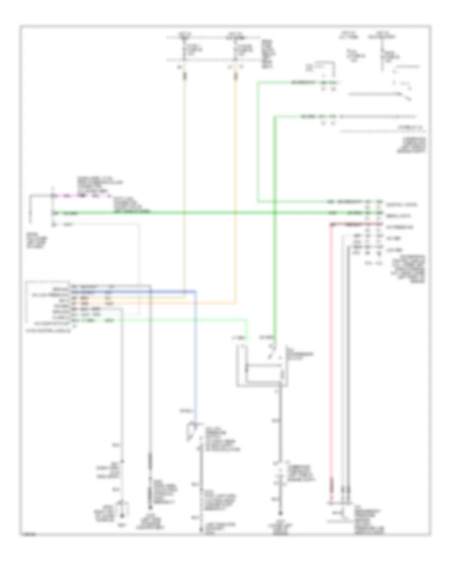
Automatic A/C Wiring Diagram, Short Wheel Base (2 of 2) for Buick Rainier 2004
List of elements for Automatic A/C Wiring Diagram, Short Wheel Base (2 of 2) for Buick Rainier 2004:
- (4.2l)
- (5.3l)
- (forward lamp harn, 20 cm from windshield washer pump breakout)
- (left radiator support) g103
- (not used)
- (w/ rear a/c)
- +5v ref
- 0-12v pulse
- 4.2l
- 4.2l 5.3l
- 5.3l
- A/c compressor clutch
- A/c fuse 30 10a
- A/c low pressure switch (at right rear of eng compt, on accumulator)
- A/c press sig
- A/c refrigerant pressure sensor (on high pressure line near a/c comp)
- A/c relay 44
- A12
- Ambient light sens
- Aux blwr hi spd
- Aux blwr lo spd
- Aux mode dr
- Auxiliary blower motor (w/ rear a/c) (below center of dash)
- Auxiliary console mode actuator (w/ rear a/c) (below center of dash)
- Auxiliary hvac control module
- B11
- B12
- Batt
- Body control module (beneath left rear seat, on rear fuse block)
- Class 2 data
- Comp rly cntrl
- Cooling fan
- D11
- Data link connector (on bottom of left side of dash)
- Eng fan fuse 20 10a
- F10
- F12
- Fan relay
- G103 (under left radiator support)
- G107 (lower left side of engine)
- G108 (lower left side of engine)
- G201
- Ground
- Hall sensor
- High spd maf
- Hot at all times
- Hot in run or start
- Ign e fuse 22 10a
- Low ref
- Low reference
- Lt sunload sens sig
- Mode
- Off
- Powertrain control module (4.2l: upper left side of engine) (5.3l: near lower left front of engine)
- Rt sunload sens sig
- S101
- S103 (fwd lamp harn, 8 cm from rear washer pump breakout)
- S113
- S232 (w/ immobilizer) (i/p harn, 10 cm from steering column connector)
- S307 (console harn)
- Serial data
- Sp201 (right front of lower console)
- Sp205 (behind left of dash)
- Underhood fuse block (left side of engine compt)
Compressor Wiring Diagram for Buick Rainier 2004
List of elements for Compressor Wiring Diagram for Buick Rainier 2004:
- (dash harn, 10 cm from steering column connector) (w/ immobilizer) s232
- (left radiator support) g103
- +5v ref
- 4.2l 5.3l
- 5.3l 4.2l
- A/c compressor clutch
- A/c comp status
- A/c fuse 30 10a
- A/c low press sw
- A/c low pressure switch (at right rear of eng compt, on accumulator)
- A/c press sig
- A/c refrigerant pressure sensor (on high pressure line near a/c comp)
- A/c relay 44
- A12
- B11
- B12
- Class 2
- Comp rly cntrl
- D11
- Data link connector (on bottom of left side of dash)
- F10
- F12
- G102 (left side of engine compartment)
- G107 (lower left side of engine)
- G201
- Ground
- Hot at all times
- Hot in run
- Hot in run or start
- Hvac 1 fuse 39 10a
- Hvac control module
- Hvac-b fuse 36 10a
- Ign 3
- Ign e fuse 22 10a
- Low ref
- Power
- Powertrain control module (4.2l: upper left side of engine) (5.3l: near lower left front of engine)
- Rear fuse block (below left rear seat)
- S103 (fwd lamp harn, 8 cm from rear washer pump breakout)
- S202 (dash harn, 16.5 cm from strng col conn breakout)
- S211 (dash harn, 16 cm from sp201)
- Serial data
- Sp201 (right frt of lower console)
- Sp205 (on lower left side of dash)
- Underhood fuse block (left side of engine compt)

 Čeština
 Dansk
Dansk Deutsch
 Ελληνικά
 English
 English
 Español
 Suomi
Suomi Français
 Français
 עברית
עברית Hrvatski
 Magyar
 Italiano
 日本語
日本語 한국어
한국어 Nederlands
 Polski
 Português
 Português
 Română
 Русский
 Slovenčina
 Slovenščina
 Svenska
 Türkçe