POWER DISTRIBUTION
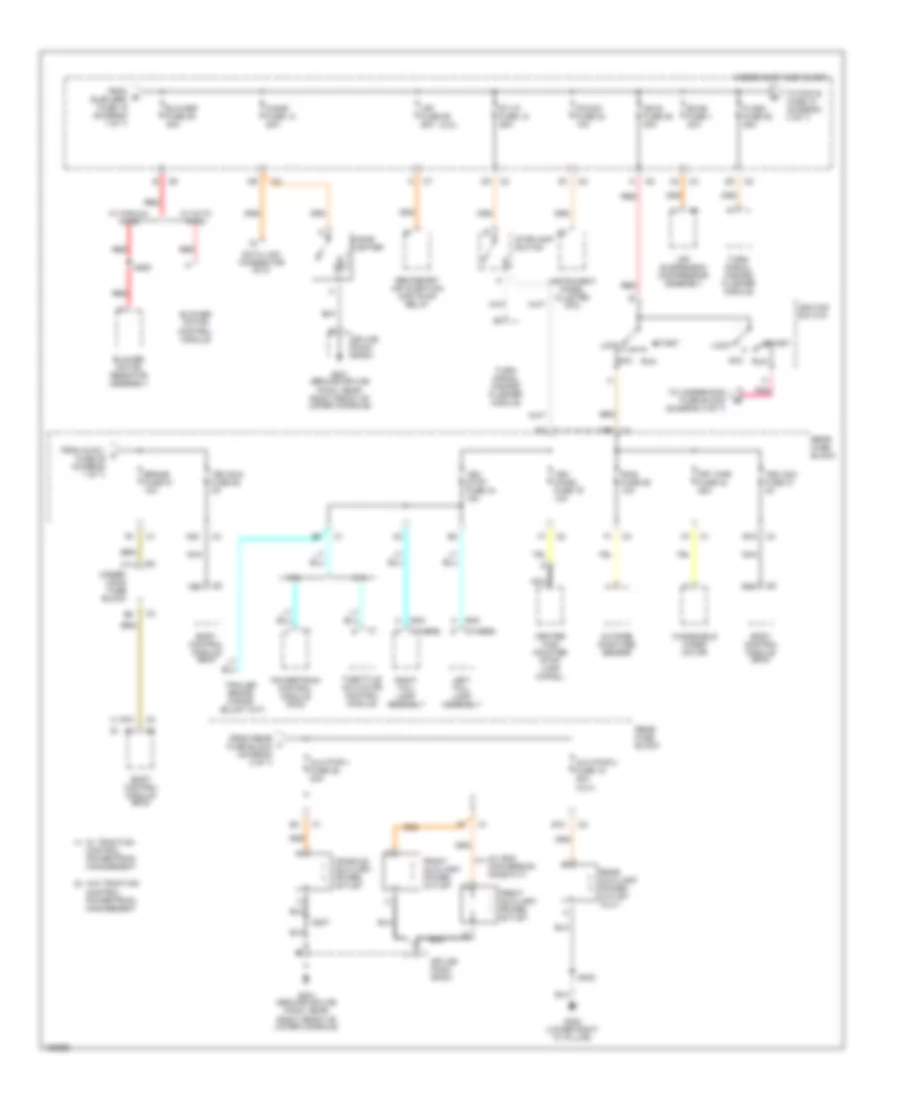
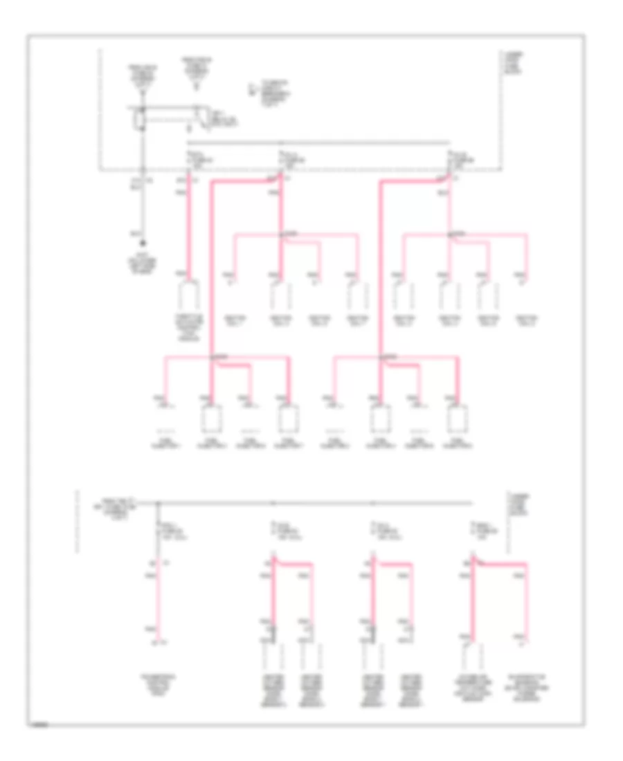
Power Distribution Wiring Diagram (1 of 7) for Buick Rainier 2004
 https://portal-diagnostov.com/license.html
Automotive Electricians Portal FZCO
Automotive Electricians Portal FZCO
https://portal-diagnostov.com/license.html
https://portal-diagnostov.com/license.html
Automotive Electricians Portal FZCO
Automotive Electricians Portal FZCO
List of elements for Power Distribution Wiring Diagram (1 of 7) for Buick Rainier 2004:
- (4.2l)
- (5.3l)
- (i/p harn, 18 cm (7in) from the a/t pnk
- (not used)
- (olds & buick)
- (short wheelbase w/ manual temperature control)
- (w/ short wheelbase or xuv)
- 1-2 shift solenoid (1-2 ss) valve
- 2-3 shift solenoid (2-3 ss) valve
- 3-2 shift solenoid 3-2 ss) valve
- 4wd fuse 48 15a
- 5.3l
- A11
- A18
- Abs fuse 33 60a
- Acc
- Air suppression compressor assembly (w/ auto air level control)
- Atc fuse 8 30a
- Automatic transmission
- Automatic transmission shift lever
- Auxiliary hvac control mode actuator
- Auxiliary mode actuator
- B11
- Battery
- Battery fuse 48 125 a
- Body control module (bcm)
- C175
- Crank fuse 17 10a
- Defrost actuator
- Electronic brake control module
- Electronic brake control module (ebcm)
- Elek brk fuse 19 30a
- F11
- Flat- wire
- Front axle actuator
- Fusible link (8 ga-red)
- Generator
- Hvac control module
- Hvac control module (w/ manual temperature control)
- Hvac fuse 44 30a
- Hvac i fuse 39 10a
- Ign a fuse 34 40a
- Ign o fuse 47 10a
- Ignition switch
- Left mode temperature actuator
- Lock
- Mode actuator
- Ohms
- Pnk
- Powertrain control module (pcm)
- Rear fuse block
- Recirculation actuator
- Red
- Right air temperature actuator
- Run
- S133
- S309
- Shift lever connector breakout) s320
- Start
- Starter
- Starter relay
- Tbc ig fuse 50 3a
- To blower fuse 35 (diagram 2 of 7)
- To brake fuse 51 (diagram 2 of 7)
- To rear fuse block lgm/dsm fuse 6 (diagram 4 of 7)
- Torque converter clutch (tcc) solenoid valve
- Torque converter clutch pulse width modulation (tcc pwm) solenoid valve
- Traction control switch
- Traction control switch (w/ automatic temperature control)
- Trailer connector
- Trailer fuse 32 30a
- Transfer case encoder motor
- Transfer case shift control module
- Transfer case shift control switch
- Turn/signal multifunction switch
- Under- hood fuse block
- Underhood fuse block
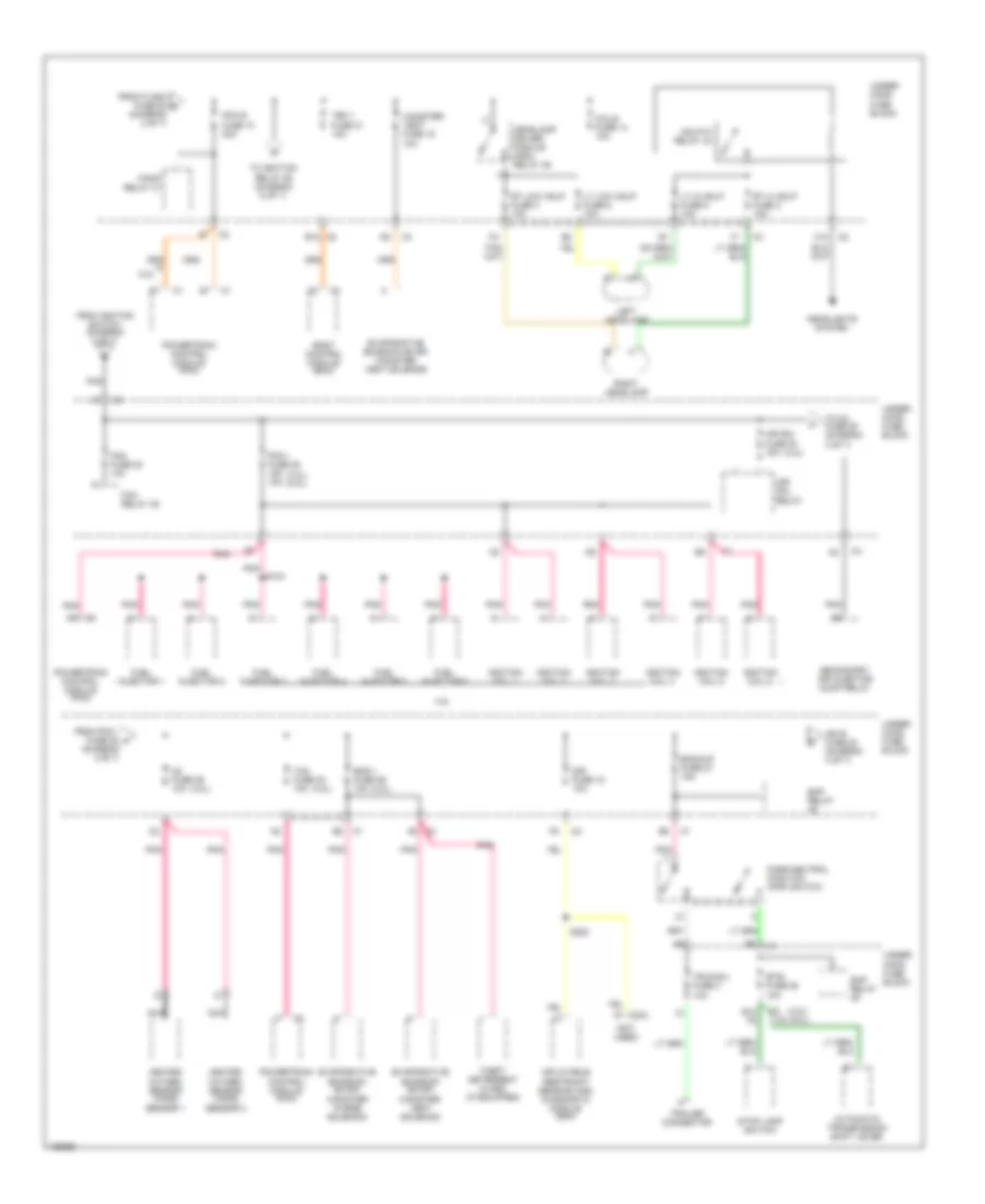
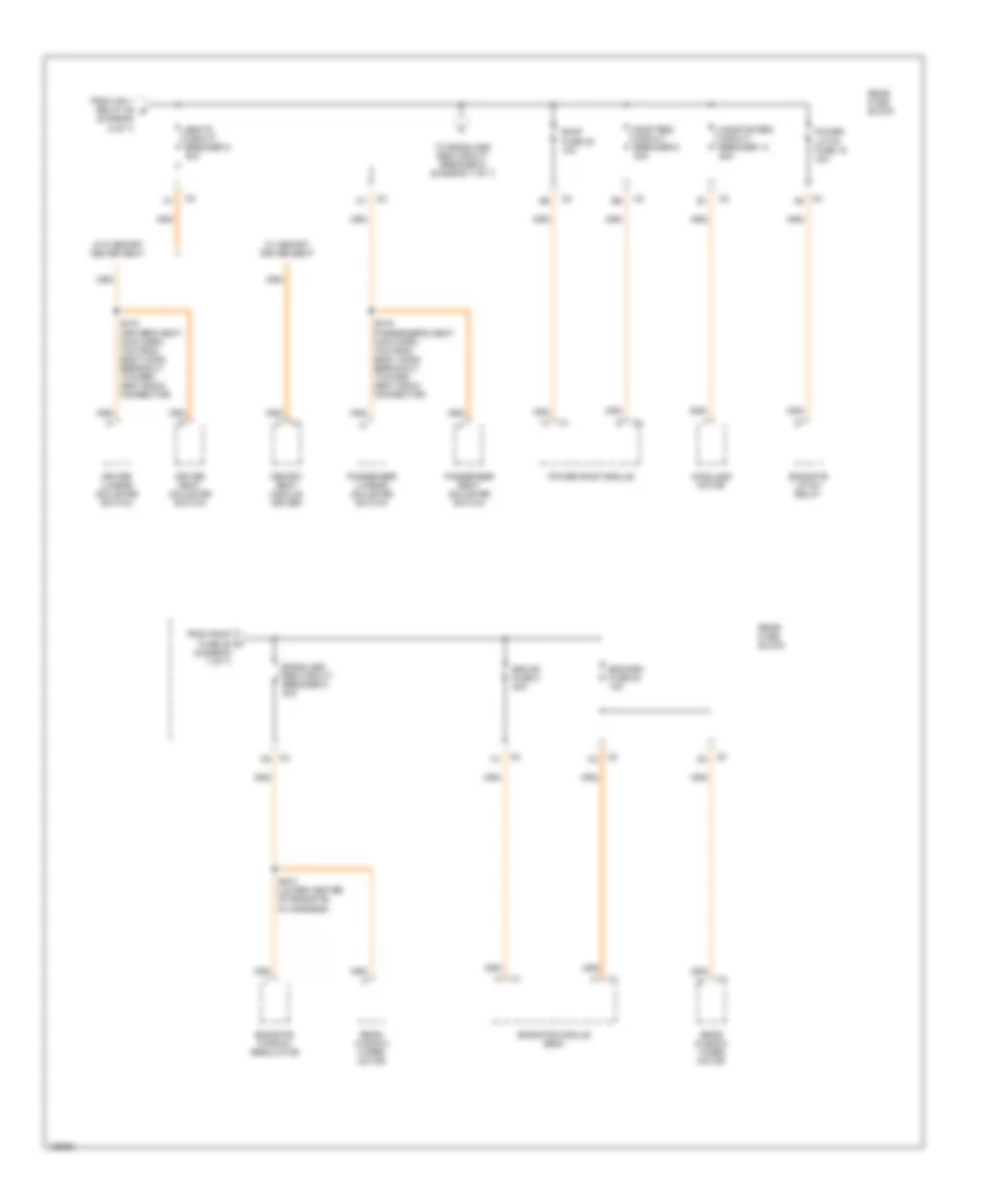
Power Distribution Wiring Diagram (2 of 7) for Buick Rainier 2004
 https://portal-diagnostov.com/license.html
Automotive Electricians Portal FZCO
Automotive Electricians Portal FZCO
https://portal-diagnostov.com/license.html
https://portal-diagnostov.com/license.html
Automotive Electricians Portal FZCO
Automotive Electricians Portal FZCOList of elements for Power Distribution Wiring Diagram (2 of 7) for Buick Rainier 2004:
- (1)
- (2)
- (2) w/o traction control powertrain management
- (4.2l)
- (from rear l fuse block (diagram 4 of 7)
- (w/ gmc conversion name plt)
- 4.2l
- 5.3l
- A20
- Acc
- Air fuse 56 60a
- Air suspension compressor assembly
- Aux pwr 1 fuse 46 20a
- Aux pwr 2 fuse 15 20a (xuv)
- B10
- B15
- Blower fuse 35 40a
- Blower motor control module
- Blower motor resistor assembly
- Body control module (bcm)
- Brake fuse 51 10a
- C11
- Center high mounted stop lamp (chmsl)
- Cigar fuse 13 20a
- Cigar lighter
- Console auxiliary power outlet
- Control powertrain management
- Data link connector (dlc)
- E10
- Ecas fuse 1 30a
- Flash fuse 52 25a
- From b elek brk fuse 19 (diagram 1 of 7)
- From hvac i c fuse 39 (diagram 1 of 7)
- Front auxiliary power outlet
- Frt wpr fuse 33 25a
- G201 (ground splice pack, near right front of lower console)
- G402 (lower right "d" pillar)
- Gmc
- Ign b fuse 36 40a
- Ignition switch
- Instrument panel cluster (ipc)
- Ipc/dic fuse 24 10a
- Left tail- lamp assembly
- Lock
- Nca
- Others
- Outside moisture sensor
- Pnk
- Powertrain control module (pcm)
- Rain fuse 29 10a
- Rear auxiliary power outlet (xuv)
- Rear fuse block
- Red
- Right tail- lamp assembly
- Run
- S250
- S307
- S402
- Secondary air injection (air) pump relay
- Splice pack sp201
- St/lp fuse 12 25a
- Start
- Stoplamp switch
- Tbc acc fuse 31 3a
- Tbc run fuse 52 3a
- Throttle actuator control module
- To pcm b fuse 10 (diagram 3 of 7)
- To underhood fuse block (diagram 3 of 7)
- Turn/ signal hazard flasher module
- Under- hood fuse block
- Underhood fuse block
- Veh chmsl fuse 16 10a
- Veh stop fuse 34 15a
- W/ auto hvac
- W/ manual hvac
- W/ traction (1)
- Windshield wiper motor
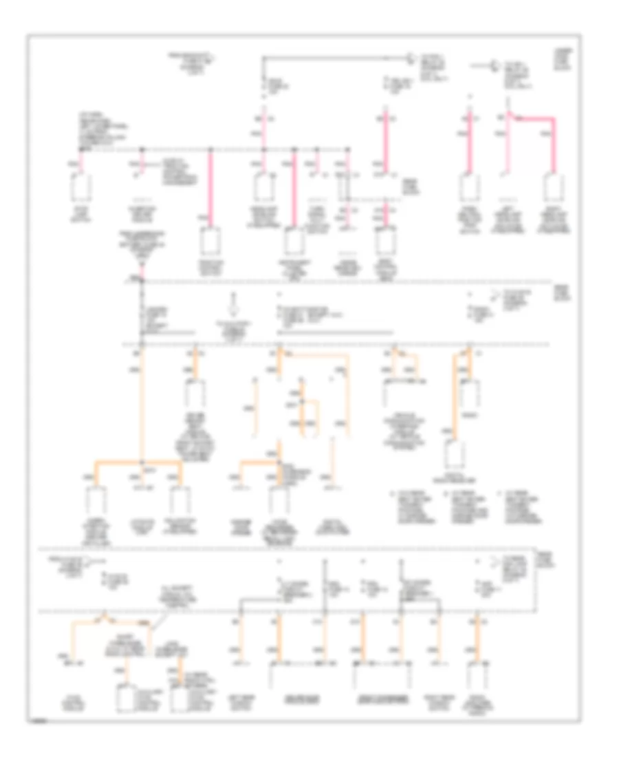
Power Distribution Wiring Diagram (3 of 7) for Buick Rainier 2004
 https://portal-diagnostov.com/license.html
Automotive Electricians Portal FZCO
Automotive Electricians Portal FZCO
https://portal-diagnostov.com/license.html
https://portal-diagnostov.com/license.html
Automotive Electricians Portal FZCO
Automotive Electricians Portal FZCOList of elements for Power Distribution Wiring Diagram (3 of 7) for Buick Rainier 2004:
- (4.2l)
- (4.2l) (5.3l)
- (not used)
- 4.2l
- 5.3l
- Air sol fuse 54 15a
- Air sol relay
- Automatic transmission shift lever
- Backup fuse 27 15a
- Body control module (bcm)
- Btsi fuse 25 10a
- C12
- C304
- Canister vent fuse 15 10a
- Coils fuse 14 10a
- E10 f8
- E12
- Eap relay
- Eng 1 fuse 26 10a
- Evaporative emission (evap) canister purge solenoid
- Evaporative emission (evap) canister vent solenoid
- F/pmp relay 41
- Fan fuse 20 10a
- Fan relay 45
- From flash fuse 52 d (diagram 2 of 7)
- From ignition switch (diagram 2 of 7)
- From pcm i fuse 28 f (diagram 3 of 7)
- Fuel injector 1
- Fuel injector 2
- Fuel injector 3
- Fuel injector 4
- Fuel injector 5
- Fuel injector 6
- Hdlp-hi relay 43
- Headlamp driver module (hdm) relay 46
- Headlights system
- Heated oxygen sensor (ho2s) sensor 1
- Heated oxygen sensor (ho2s) sensor 2
- Ign e fuse 22 (diagram 4 of 7)
- Ignition coil 1
- Ignition coil 2
- Ignition coil 3
- Ignition coil 4
- Ignition coil 5
- Ignition coil 6
- Inflatable restraint sensing and diagnostic module (sdm)
- Left headlamp
- Lt hi hdlp fuse 5 10a
- Lt low hdlp fuse 6 10a
- Nca
- O2 fuse 29 10a
- Park/neutral position (pnp) switch
- Pcm b fuse 10 20a
- Pcm i fuse 28 15a 10a
- Pnk
- Powertrain control module (pcm)
- Right headlamp
- Rt hi hdlp fuse 2 10a
- Rt low hdlp fuse 3 10a
- S104
- S220
- Secondary air injector dump relay
- Sir fuse 18 10a
- Stop lamp switch
- Tac fuse 23 10a
- Tbc 1 fuse 31 10a
- Theft deterrent alarm (if equipped)
- To ignition relay 58 (diagram 6 of 7)
- To o2 fuse 29 (diagram 3 of 7)
- Trailer connector
- Trlr b/u fuse 4 10a
- Under- hood fuse block
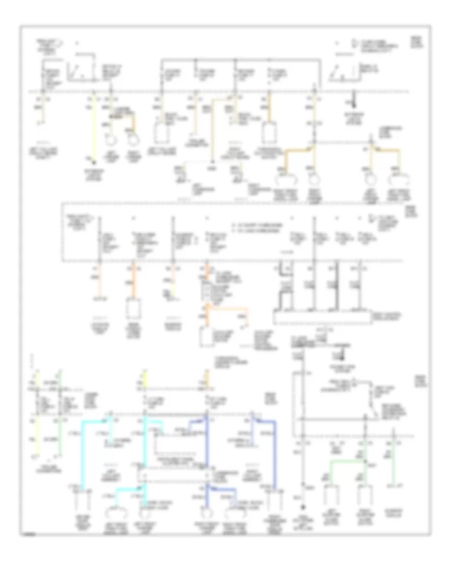
Power Distribution Wiring Diagram (4 of 7) for Buick Rainier 2004
 https://portal-diagnostov.com/license.html
Automotive Electricians Portal FZCO
Automotive Electricians Portal FZCO
https://portal-diagnostov.com/license.html
https://portal-diagnostov.com/license.html
Automotive Electricians Portal FZCO
Automotive Electricians Portal FZCOList of elements for Power Distribution Wiring Diagram (4 of 7) for Buick Rainier 2004:
- (except xuv) (xuv)
- (i/p harn, above dash left lower panel, 11 cm from steering column toward dlc) s239
- (w/ rear e
- (w/ rear f
- (w/ rear radio ctrl) (others)
- (w/o rear d
- A16 a2
- A19
- All except manual a/c temperature control
- Amp fuse 11 20a
- Auxiliary hvac control module
- Body control module (bcm)
- C10
- Cobra intention module (dealer installed)
- Communication system)
- D10
- D12
- Ddm fuse 10 10a
- Digital radio receiver
- Digital video disc (dvd) player
- Driver door module (ddm)
- Driver memory seat module (w/ deluxe front bucket seat, w/ 6-way power seat adjuster)
- E12
- From backup fuse 27 g (diagram 3 of 7)
- From hvac b fuse 36 h (diagram 4 of 7)
- From underhood fuse block, battery fuse 48 (diagram 1 of 7)
- Front passenger door module (fpdm)
- Garage door opener
- Headlamp leveling switch (if equipped)
- Hvac b fuse 36 10a
- Hvac control module
- Ign e fuse 22 10a
- Inclination sensor (if equipped)
- Inside rearview mirror
- Instrument panel cluster (ipc)
- Inverting driver module
- Left headlamp leveling actuator (if equipped)
- Left rear window switch
- Lgm/dsm fuse 19 10a (except xuv)
- Liftgate module (lgm)
- Long wheelbase except xuv
- Lt doors circuit breaker 2 25a
- Oh batt/onstar fuse 27 fuse 26 10a
- Olds w/ traction control powertrain management
- Park/ neutral position (pnp) switch
- Pdm fuse 12 10a
- Pnk
- Radio
- Radio amplifier (w/ premium radio)
- Radio fuse 41 15a
- Rear fuse block
- Red
- Right headlamp leveling actuator (if equipped)
- Right rear window switch
- Rt doors circuit breaker 1 25a
- S340 (overhead console harn)
- S341
- S374
- Seat enter- tainment package and garage door opener)
- Seat enter- tainment package, w/ garage door opener)
- Seat enter- tainment package, w/o garage door opener)
- Short wheelbase & xuv w/ rear radio control
- Stop lamp switch
- Tbc ign 1 fuse 16 10a
- To aux pwr 1 fuse 46 (diagram 2 of 7)
- To hvac b fuse 36 (diagram 4 of 7)
- To ign 1 relay 58 (diagram 6 of 7) (5.3l only)
- To pcm 1 relay 28 (diagram 6 of 7) (5.3l only)
- To rear fog lamp relay 45 (diagram 5 of 7)
- Traction control switch
- Turn/ signal mult- function switch
- Under- hood fuse block
- Vehicle communication interface module (w/ vehicle
- Voice recorder (w/ recorder recall con- venience)
Power Distribution Wiring Diagram (5 of 7) for Buick Rainier 2004
 https://portal-diagnostov.com/license.html
Automotive Electricians Portal FZCO
Automotive Electricians Portal FZCO
https://portal-diagnostov.com/license.html
https://portal-diagnostov.com/license.html
Automotive Electricians Portal FZCO
Automotive Electricians Portal FZCOList of elements for Power Distribution Wiring Diagram (5 of 7) for Buick Rainier 2004:
- (buick, chev, olds)
- (chev, buick)
- (diagram 4 of 7)
- (diagram 5 of 7)
- (gmc)
- (gmc, olds)
- (license lamp harn) s909
- (not used)
- (others)
- (others) b
- (w/ long wheelbase) h
- (w/ short wheelbase) g
- A10
- A11
- A12
- Auxiliary blower motor
- Auxiliary blower motor control processor
- B d
- B10
- B13
- B17
- Blower motor auxiliary fuse 30a
- Body control module (bcm)
- D (gmc)
- D10
- Driver door module (ddm)
- Exterior lights system
- F park fuse 37 10a
- Flat wire
- From amp fuse 11 i
- From amp fuse 11 j
- From tbc 4 fuse 40 (diagram 5 of 7)
- Front passenger door module (fpdm)
- G h
- G302 (on lower left "b" pillar)
- Instrument panel cluster (ipc)
- Left clearance lamp
- Left front marker lamp
- Left front park/turn signal lamp
- Left license lamp
- Left quarter glass switch
- Left taillamp assembly
- Left taillamp circuit board
- Left taillamp circuit board (chevy)
- Lgm 2 fuse 3 30a (except xuv)
- Liftgate module (lgm)
- Lr park fuse 14 10a
- Lt turn fuse 38 10a
- Nca
- Others
- Park lp relay 50
- Power tops system
- Rear fuse block
- Rear window wiper motor
- Retained accessory power (rap) relay 22
- Right clearance lamp
- Right front marker lamp
- Right front park/turn signal lamp
- Right license lamp
- Right quarter glass switch
- Right taillamp assembly
- Right taillamp circuit board
- Rr fog fuse 5 10a (except xuv)
- Rr fog lp relay 45 (except xuv)
- Rr hvac fuse 13 30a (except xuv)
- Rr park fuse 17 10a
- Rr wiper circuit breaker 9 15a (except xuv)
- Rt turn fuse 43 10a
- S301
- S302
- S360
- Sunroof fuse 20 fuse 28 20a
- Sunroof module
- Tan
- Tbc 2 fuse 7 10a
- Tbc 3 fuse 4 10a
- Tbc 4 fuse 40 10a
- Tbc 5 fuse 32 10a
- To rr wiper circuit breaker 9 (diagram 5 of 7)
- To vent wdo fuse (diagram 5 of 7)
- Tr park fuse 42 10a
- Trailer connector
- Trailer connectors
- Trl l trn fuse 51 10a
- Trl r trn fuse 50 10a
- Turn/signal hazard flasher module
- Turn/signal multifunction switch
- Under- hood fuse block
- Underhood fuse block
- Vent wdo fuse 20 20a
- W/ long wheelbase (except xuv)
- W/ long wheelbase except xuv
Power Distribution Wiring Diagram (6 of 7) for Buick Rainier 2004
 https://portal-diagnostov.com/license.html
Automotive Electricians Portal FZCO
Automotive Electricians Portal FZCO
https://portal-diagnostov.com/license.html
https://portal-diagnostov.com/license.html
Automotive Electricians Portal FZCO
Automotive Electricians Portal FZCOList of elements for Power Distribution Wiring Diagram (6 of 7) for Buick Rainier 2004:
- (5.3l)
- (diagram 4 of 7)
- C12
- C2 c12
- D12
- E12
- Eng 1 fuse 26 10a
- Etc fuse 23 15a
- Evaporative emission (evap) canister purge solenoid)
- From ign e fuse 22 (diagram 4 of 7)
- From pcm b fuse 10 (diagram 3 of 7)
- From tbc ign 1 fuse 16 o
- Fuel injector 1
- Fuel injector 2
- Fuel injector 3
- Fuel injector 4
- Fuel injector 5
- Fuel injector 6
- Fuel injector 7
- Fuel injector 8
- G107 (on lower left side of eng)
- Heated oxygen sensor (h02s) bank 1 sensor 1
- Heated oxygen sensor (h02s) bank 1 sensor 2
- Heated oxygen sensor (h02s) bank 2 sensor 1
- Heated oxygen sensor (h02s) bank 2 sensor 2
- Ign 1 relay 58 (5.3l only)
- Ignition coil 1
- Ignition coil 2
- Ignition coil 3
- Ignition coil 4
- Ignition coil 5
- Ignition coil 6
- Ignition coil 7
- Ignition coil 8
- Inj a fuse 55 15a
- Inj b fuse 56 15a
- Intake air temperature (iat) mass air flow (maf) sensor
- Nca
- O2 a fuse 53 15a
- O2 b fuse 54 15a
- Pcm 1 fuse 28 10a
- Pnk
- Powertrain control module (pcm)
- S100
- S102
- S108
- S109
- Throttle actuator control (tac) module
- To seats circuit breaker 8 (diagram 7 of 7)
- Under- hood fuse block
Power Distribution Wiring Diagram (7 of 7) for Buick Rainier 2004
 https://portal-diagnostov.com/license.html
Automotive Electricians Portal FZCO
Automotive Electricians Portal FZCO
https://portal-diagnostov.com/license.html
https://portal-diagnostov.com/license.html
Automotive Electricians Portal FZCO
Automotive Electricians Portal FZCOList of elements for Power Distribution Wiring Diagram (7 of 7) for Buick Rainier 2004:
- (diagram 6 of 7)
- (diagram 7 of 7)
- Driver lumbar adjuster switch
- Driver seat adjuster switch
- Egm #2 fuse 3 30a
- Egm/dsm fuse 23 10a
- Endgate latch relay
- Endgate module (egm)
- Endgate window regulator
- Endglass reg circuit breaker 9 30a
- From ign 1 relay 58 s
- From roof fuse 25 t
- Memory seat module driver
- Midgate reg circuit breaker 13 25a
- Midglass motor
- Passenger lumbar adjuster switch
- Passenger seat adjuster switch
- Power latch fuse 19 15a
- Power roof module
- Rear fuse block
- Rear window wiper motor
- Roof fuse 25 10a
- Roof reg circuit breaker 6 30a
- S318 (driver's seat main harn, 7cm from body conn breakout, toward seat back connector)
- S319 passenger's seat main harn, 7cm from body conn breakout, toward seat back connector)
- S910 (lower center of endgate, in harness)
- Seats circuit breaker 8 30a
- To endglass reg circuit breaker 9 (diagram 7 of 7)
- W/ memory driver seat
- W/o memory driver seat

 Čeština
 Dansk
Dansk Deutsch
 Ελληνικά
 English
 English
 Español
 Suomi
Suomi Français
 Français
 עברית
עברית Hrvatski
 Magyar
 Italiano
 日本語
日本語 한국어
한국어 Nederlands
 Polski
 Português
 Português
 Română
 Русский
 Slovenčina
 Slovenščina
 Svenska
 Türkçe
