POWER DISTRIBUTION
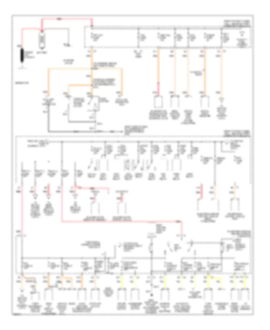
Power Distribution Wiring Diagram (1 of 4) for Buick Rendezvous CX 2007
 https://portal-diagnostov.com/license.html
Automotive Electricians Portal FZCO
Automotive Electricians Portal FZCO
https://portal-diagnostov.com/license.html
https://portal-diagnostov.com/license.html
Automotive Electricians Portal FZCO
Automotive Electricians Portal FZCO
List of elements for Power Distribution Wiring Diagram (1 of 4) for Buick Rendezvous CX 2007:
- (console harness, 6.5 cm from cigar lighter breakout) s315
- (front of right wheel well, above battery) underhood fuse block
- (i/p harness, behind left side of dash) s220
- (in center console) center console fuse block
- (not used)
- (right side of dash, on underside of cross-car beam) g200
- A/c clu fuse 10a
- A/c clu relay
- A12
- Abs sol fuse 25a
- Absmtr fuse 40a
- Acc pwr fuse 28 10a
- Accy diode 43 (diagram 3 of 4)
- Accy relay
- Audio amplifier (w/ performance enhance audio)
- Automatic a/c
- Automatic level control (alc) sensor (if equipped)
- Auxiliary drop connector
- B12
- Batt 1 fuse 60a
- Batt 2 fuse 60a
- Batt 3 fuse 60a
- Battery
- Bcm fuse 10a
- Blower motor control module
- Blower motor resistor assembly
- Body control module (bcm)
- C1 f10
- C11
- C2 a10
- Cigar lighter
- Console auxiliary power outlet
- Cool fan 1 fuse 30a
- Cool fan 1 relay
- Cool fan 2 fuse 40a
- Cool fan 2 relay
- Cool fan s/p relay
- Crank relay
- D11
- D12
- Data link connector (dlc)
- Digital radio receiver
- Digital video disc (dvd) player (if equipped)
- Driver window switch
- Dvd fuse 15a
- E11
- E12
- Ecm fuse 10a
- Elc cmprsr fuse 15 10a
- Electronic brake control module (ebcm) (if equipped)
- Evaporative emission (evap) canister vent solenoid valve
- F11
- F12
- Fog lps fuse 10a
- Fog lps relay
- From ign 1/ign 3 fuse, (diagram 1 of 4)
- From k
- Frt aux fuse 20a
- Fuel pump fuse 15a
- Fuel pump relay
- G200 (right side of dash, on underside of cross- car beam)
- Generator
- Hazrd lamp fuse 15a
- Head up display (hud) (if equipped)
- Horn fuse 15a
- Horn relay
- Hud fuse 39 10a
- I/p switch assembly
- Ign 1 fuse 60a
- Ign 1/ ign 3 fuse 20a
- Ign 3 fuse 40a
- Is lamp fuse 36 20a
- Manual a/c
- Nca
- Park lps fuse 15a
- Park lps relay
- Passenger window switch
- Pk3 fuse 42 10a
- Pnk
- Powertrain control module (pcm)
- Pwr sunroof fuse 34 20a
- Pwr wndw circuit breaker 35 30a
- Radio
- Rap relay
- Rdo amp fuse 38 25a
- Rdo fuse 37 15a
- Rear window wiper motor
- Red
- Red red
- Rr wpr sw fuse 32 20a
- S band fuse 2a
- S213
- S314
- Starter motor
- Stoplamp switch
- Strtr sol fuse 40a
- Sunroof module (if equipped)
- Tcm fuse 10a
- Theft deterrent control module
- To batt 1 fuse, (diagram 1 of 4)
- To ign relay 23 (diagram 3 of 4)
- To ignition relay (diagram 2 of 4)
- To ignition switch pin b (diagram 3 of 4)
- To ignition switch pin f (diagram 3 of 4)
- To ipc/hvac/ sec/rke fuse 41 (diagram 4 of 4)
- To rear defog relay 20 (diagram 3 of 4)
- To rr aux power outlet fuse 14 (diagram 4 of 4)
- Turn signal/ hazard flasher module 10
- Turn signal/ multi- function switch
- Vehicle communi- cation unit (vcu)
- Vent sol fuse 10a
- W/ digital radio
- W/ onstar
- Windshield wiper motor
- Wpr/wsw fuse 29 25a
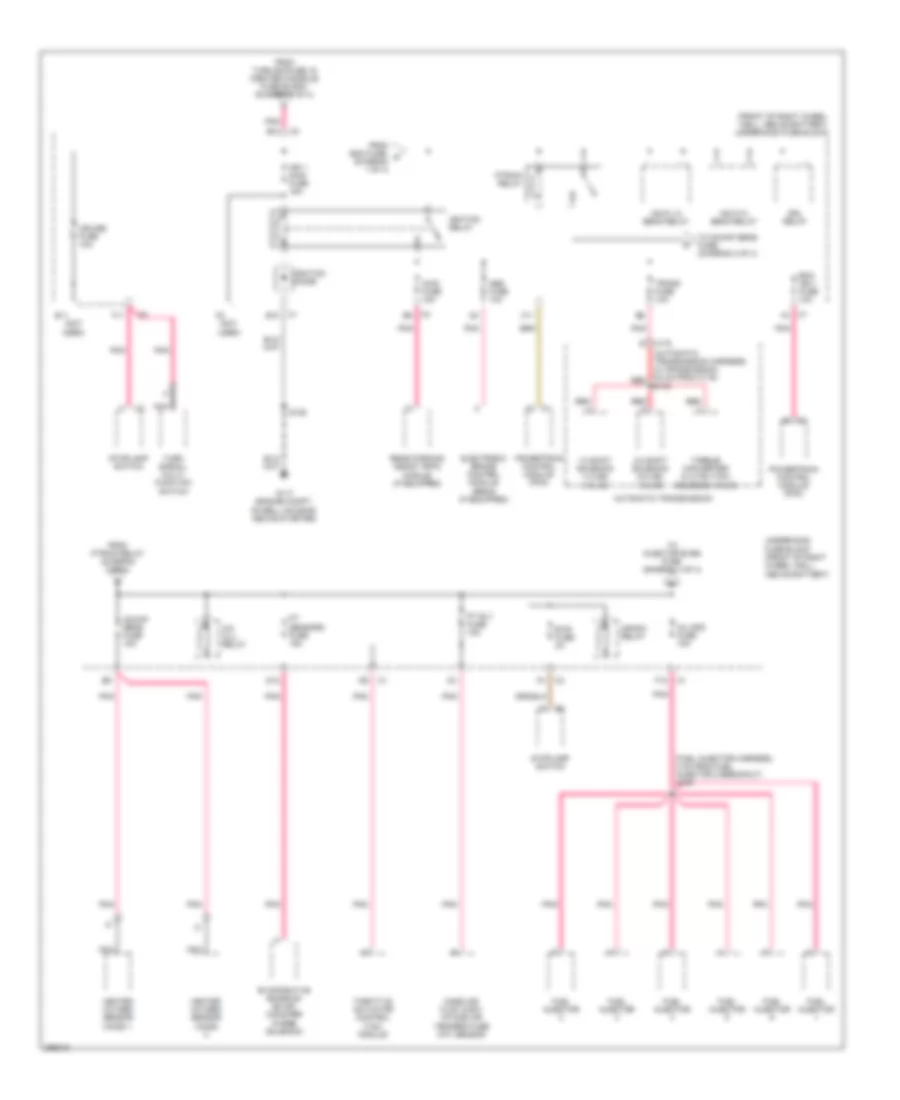
Power Distribution Wiring Diagram (2 of 4) for Buick Rendezvous CX 2007
 https://portal-diagnostov.com/license.html
Automotive Electricians Portal FZCO
Automotive Electricians Portal FZCO
https://portal-diagnostov.com/license.html
https://portal-diagnostov.com/license.html
Automotive Electricians Portal FZCO
Automotive Electricians Portal FZCOList of elements for Power Distribution Wiring Diagram (2 of 4) for Buick Rendezvous CX 2007:
- (automatic transmission harness, in transmission, 9.5 cm from c175) red
- (front of right wheel well, above battery) underhood fuse block
- (fuel injector harness, 4 cm from fuel injector 2 breakout) s109
- (not used)
- 1-2 shift solenoid (1-2 ss) valve
- 2-3 shift solenoid (2-3 ss) valve
- A/c clu relay
- Abs fuse 10a
- Automatic transmission
- Awd fuse 15a
- B10
- Btsi fuse 2a
- C11
- C175 e
- Crank relay
- Cruise fuse 10a
- D12
- Drl relay
- E11
- E12
- Ecm ign 1 fuse 10a
- Electronic brake control module (ebcm) (if equipped)
- Evaporative emission (evap) canister purge solenoid
- F11
- F12
- From ecm fuse, c (diagram 1 of 4)
- From ptrain relay (diagram 2 of 4)
- From turn sig fuse 19 (center console fuse block) (diagram 3 of 4)
- Fuel injector
- G117 (engine compt, on bell housing, above starter)
- Hdlp hi beam relay
- Hdlp lo beam relay
- Heated oxygen sensor (ho2s)
- Heated oxygen sensor (ho2s) 1
- Ign 1 main fuse 15a
- Ignition diode
- Ignition relay
- Inj odd fuse 15a
- Mass air flow (maf)/ intake air temperature (iat) sensor
- Nca
- O2/maf sens fuse 15a
- Pnk
- Powertrain control module (pcm)
- Pt rly fuse 15a
- Pt sensors fuse 15a
- Ptrain relay
- Rear parking assist (rpa) module (if equipped)
- Red
- S106
- S175
- Stoplamp switch
- Throttle actuator control (tac) module
- To injector even fuse (diagram 4 of 4)
- To o2/maf sens fuse, (diagram 2 of 4)
- Torque converter clutch (tcc) solenoid valve
- Trans fuse 10a
- Turn signal/ multi- function switch
- Underhood fuse block (front of right wheel well, above battery)
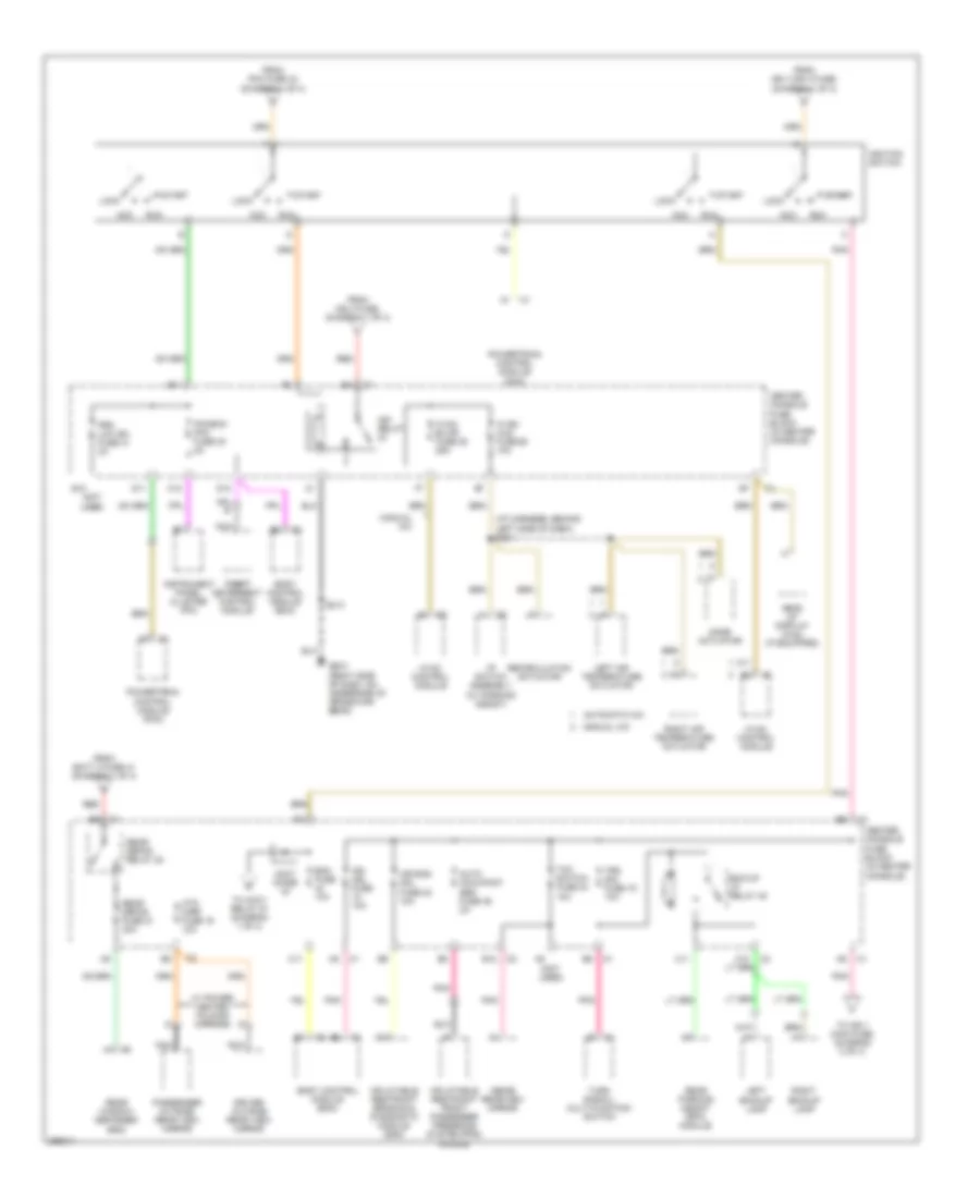
Power Distribution Wiring Diagram (3 of 4) for Buick Rendezvous CX 2007
 https://portal-diagnostov.com/license.html
Automotive Electricians Portal FZCO
Automotive Electricians Portal FZCO
https://portal-diagnostov.com/license.html
https://portal-diagnostov.com/license.html
Automotive Electricians Portal FZCO
Automotive Electricians Portal FZCOList of elements for Power Distribution Wiring Diagram (3 of 4) for Buick Rendezvous CX 2007:
- (i/p harness, behind left side of dash) s221
- (not used)
- A10
- A11
- Acc
- Accy diode
- Air bag mdl fuse 22 10a
- Auto occupant sen fuse 46 2a
- Automatic a/c
- B12
- Bck/up lp relay 45
- Bcm fuse 10a
- Body control module (bcm)
- C10
- C11
- Center console fuse block (in center console)
- D10
- D11
- Driver outside rear view mirror
- E10
- E11
- From batt 3 fuse 41 (diagram 1 of 4)
- From ign 1/ign 3 fuse, (diagram 1 of 4)
- From ign 3 fuse, (diagram 1 of 4)
- From pk3 fuse 42 (diagram 1 of 4)
- G200 (right side of dash, on underside of cross-car beam)
- Head up display (hud) (if equipped)
- Htd mirr fuse 16 10a
- Hvac blwr fuse 25 25a
- Hvac control module
- Hvac/ hud fuse 26 10a
- I/p switch assembly (w/ parking assist)
- Ign mdl fuse 10a
- Ign relay
- Ignition switch
- Inflatable restraint front passenger presence system (pps) module
- Inflatable restraint sensing & diagnostic module (sdm)
- Inside rearview mirror
- Instrument panel cluster (ipc)
- Ipc/bcm/ pk3 fuse 30 2a
- Left air temperature actuator
- Left backup lamp
- Lock
- Manual a/c
- Mode actuator
- Nca
- Passenger outside rear view mirror
- Pnk
- Powertrain control module (pcm)
- Prk lck ign fuse 31 2a
- Rear defog fuse 21 30a
- Rear defog relay 20
- Rear parking assist (rpa) module
- Rear window defogger grid
- Recirculation actuator
- Red
- Right air temperature actuator
- Right backup lamp
- Run
- S213
- Start
- Start start
- Tcc switch fuse 24 10a
- Theft theft deterrent control module
- To accy relay 27 (diagram 1 of 4)
- To ign 1 main fuse, (diagram 2 of 4)
- Trn sig fuse 19 10a
- Turn signal/ multi-function switch
- W/ power heated folding mirrors
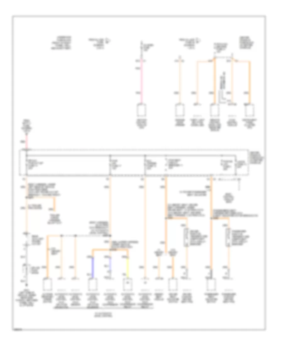
Power Distribution Wiring Diagram (4 of 4) for Buick Rendezvous CX 2007
 https://portal-diagnostov.com/license.html
Automotive Electricians Portal FZCO
Automotive Electricians Portal FZCO
https://portal-diagnostov.com/license.html
https://portal-diagnostov.com/license.html
Automotive Electricians Portal FZCO
Automotive Electricians Portal FZCOList of elements for Power Distribution Wiring Diagram (4 of 4) for Buick Rendezvous CX 2007:
- (body harness, 50 cm from c310 breakout) (w/ automatic level control) s300
- (body harness, under left rear of vehicle, 6.5cm from rear auxiliary power outlet breakout, toward front) s305
- (diagram
- (front of right wheel well, above battery)
- (passenger's seat harness, between c314 & seat adjuster motor breakouts) s366
- (w/ memory seat: driver seat harness, under driver seat, 14 cm from c313) (w/o memory seat: driver's seat harness, 4 cm from c313) s357
- 1 of 4)
- 2 of 4)
- A10
- A12
- A12 c2
- Automatic a/c
- Automatic level control (alc) compressor
- Automatic level control (alc) compressor relay
- Automatic level control (alc) inflator air switch
- Automatic level control (alc) inflator solenoid
- Automatic level control (alc) sensor
- B10
- B12
- Body control module (bcm)
- Center console fuse block (in center console)
- Driver cushion heated seat pad
- Driver positive temperature coefficient (ptc) circuit breaker
- Driver seat adjuster switch
- E12
- Elc cmprsr fuse 12 30a
- From batt 2 fuse, (diagram 1 of 4)
- From inj odd fuse,
- From is lamp fuse 36
- G401 (left side of vehicle, under rear side window, between wheel well & liftgate)
- Garage door opener
- Hvac control module
- Ignition control module (icm)
- Inj even fuse 15a
- Instrument panel cluster (ipc)
- Ipc/hvac/ sec/rke fuse 41 10a
- Lgate fuse 13 20a
- Manual a/c
- Memory seat module
- Nca
- Outside rearview mirror switch
- Passenger cushion heated seat pad
- Passenger positive temperature coefficient (ptc) circuit breaker
- Passenger seat adjuster switch
- Pnk
- Pwr dr lck fuse 3 25a
- Pwr mir fuse 17 10a
- Pwr seat circuit breaker 11 30a
- Rear auxiliary power outlet
- Red
- Remote control door lock receiver (rcdlr)
- Rr aux pwr outlet fuse 14 20a
- Splice pack sp409
- Theft light emitting diode (led)
- Underhood fuse block
- W/ automatic level control
- W/ memory seat
- W/ power passenger seat adjuster
- W/ trailer provisions
- W/0 memory seat
- W/o memory seat

 Čeština
 Dansk
Dansk Deutsch
 Ελληνικά
 English
 English
 Español
 Suomi
Suomi Français
 Français
 עברית
עברית Hrvatski
 Magyar
 Italiano
 日本語
日本語 한국어
한국어 Nederlands
 Polski
 Português
 Português
 Română
 Русский
 Slovenčina
 Slovenščina
 Svenska
 Türkçe
