AIR CONDITIONING
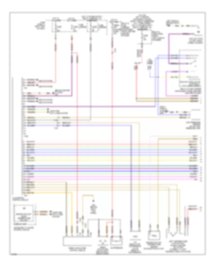
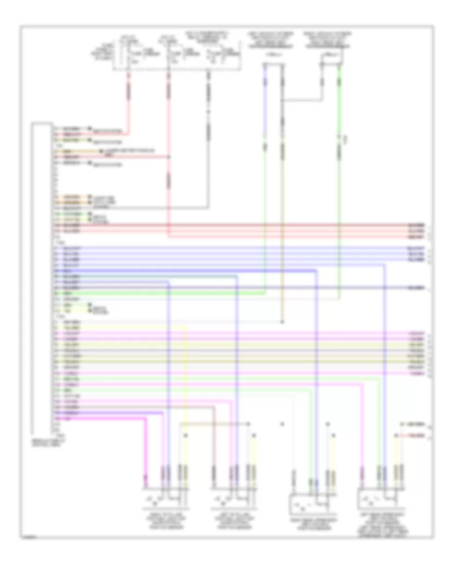
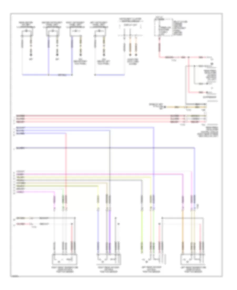
Automatic A/C Wiring Diagram, Basic (1 of 2) for Audi Q7 Premium Plus 2014
 https://portal-diagnostov.com/license.html
Automotive Electricians Portal FZCO
Automotive Electricians Portal FZCO
https://portal-diagnostov.com/license.html
https://portal-diagnostov.com/license.html
Automotive Electricians Portal FZCO
Automotive Electricians Portal FZCO
List of elements for Automatic A/C Wiring Diagram, Basic (1 of 2) for Audi Q7 Premium Plus 2014:
- (behind center of dash) g45
- (left side of engine compt) g640
- (right plenum chamber) g609
- 10a
- 12a
- 13a
- 3.0l sc
- 3.0l turbo diesel
- A/c regulator compressor valve (rear of compressor)
- Climatronic control module
- Computer data lines system
- Coolant circulation pump relay (3.ol turbo diesel)
- Coolant pump (in left front wheel housing)
- Display unit
- Engine coolant level/ temperature ind lamp
- Engine coolant temperature sensor (on radiator outlet)
- Fresh air blower (behind right side of dash)
- Fresh air blower control module
- Fresh air blower fuse 1 40a
- Fuse 10a
- Fuse 15a
- Fuse 30a
- Fuse 5a
- Fuse carrier
- Fuse panel c (right end of dash)
- G43 (behind right kick panel)
- High pressure sensor (on a/c high pressure line)
- Hot at all times
- Instrument cluster control module
- Left temperature flap motor & potentiometer/ actuator (integral to left temperature flap motor)
- Relay & fuse carrier (instrument panel-center) (center of dash)
- Relay & fuse panel (e-box) (left plenum chamber)
- Seats system
- Suppressor
- T10d
- T10f
- T16d
- T17k
- T20i
- T2q
- T3c
- T4t
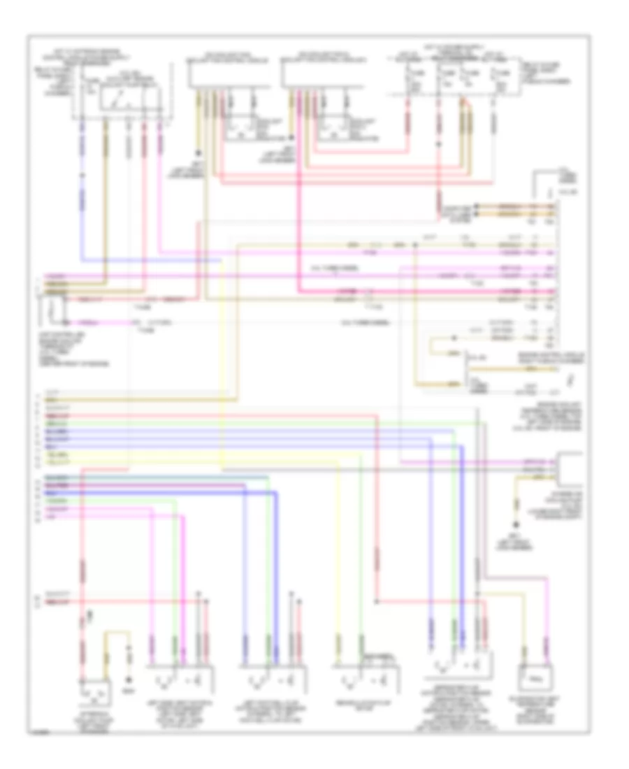
Automatic A/C Wiring Diagram, Basic (2 of 2) for Audi Q7 Premium Plus 2014
 https://portal-diagnostov.com/license.html
Automotive Electricians Portal FZCO
Automotive Electricians Portal FZCO
https://portal-diagnostov.com/license.html
https://portal-diagnostov.com/license.html
Automotive Electricians Portal FZCO
Automotive Electricians Portal FZCOList of elements for Automatic A/C Wiring Diagram, Basic (2 of 2) for Audi Q7 Premium Plus 2014:
- (3.0l sc) auxiliary engine coolant pump relay
- (on coolant fan 2) coolant fan control module 2
- (on coolant fan) coolant fan control module
- (or red)
- 10a
- 19a
- 19c
- 19d
- 19e
- 3.0l sc
- 3.0l turbo diesel
- After-run coolant pump (left front of engine)
- Charge air cooling pump (3.0l sc) (lower right front of engine compt)
- Computer data lines system
- Coolant fan (on radiator)
- Coolant fan 2 (on radiator)
- Defroster flap motor & position sensor (defroster flap motor: integral to defroster flap motor) (defroster flap position sensor: upper left side of front hvac unit)
- Engine control module (right plenum chamber)
- Engine coolant temperature sensor (3.0l turbo diesel:top left side of engine) (3.0l sc: front of engine)
- Evaporator vent temperature sensor (right side of evaporator)
- Fuse 10a
- Fuse 15a
- Fuse 40a/ 60a
- Fuse 5a
- Fuse 60a/ 40a
- G645
- G671 (left front long member)
- Hot at all times
- Left footwell flap motor & position sensor (integral to left footwell flap motor)
- Left side vent motor & position sensor (left side vent motor: left side of hvac unit)
- Map controlled engine cooling thermostat (3.0l turbo diesel) (center front of engine)
- Nca
- Recirculation flap motor
- Relay & fuse panel e-box (left plenum chamber)
- T105
- T10ab
- T10c
- T10m
- T17d
- T60
- T91
- T94
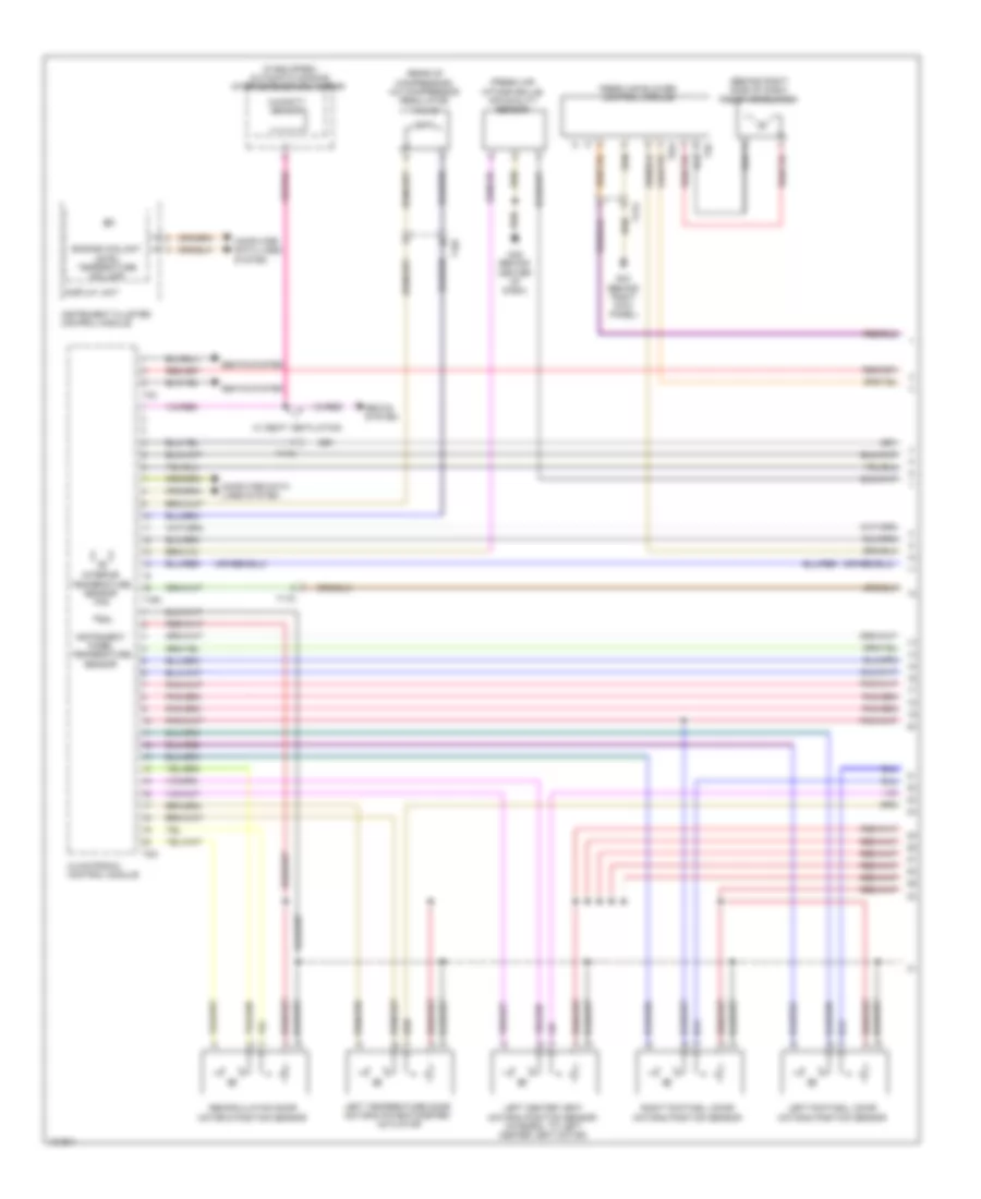
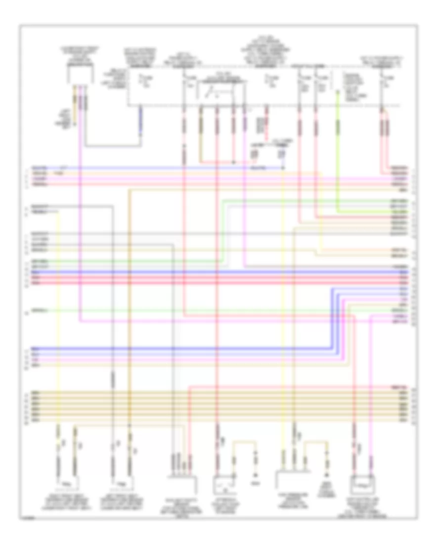
Automatic A/C Wiring Diagram, Comfort (1 of 4) for Audi Q7 Premium Plus 2014
 https://portal-diagnostov.com/license.html
Automotive Electricians Portal FZCO
Automotive Electricians Portal FZCO
https://portal-diagnostov.com/license.html
https://portal-diagnostov.com/license.html
Automotive Electricians Portal FZCO
Automotive Electricians Portal FZCOList of elements for Automatic A/C Wiring Diagram, Comfort (1 of 4) for Audi Q7 Premium Plus 2014:
- (behind right side of dash) fresh air blower
- (fresh air intake grille) air quality sensor
- (if equipped) automatic dimming interior rearview mirror
- (rear of compressor) a/c compressor regulator valve
- Climatronic control module
- Computer data lines system
- Display unit
- Engine coolant level/ temperature ind lamp
- Fresh air blower control module
- G43 (behind right kick panel)
- G45 (behind center of dash)
- Humidity sensor
- Instrument cluster control module
- Instrument panel temperature sensor
- Interior temperature sensor fan
- Left center vent motor & position sensor (integral to left center vent motor)
- Left footwell door motor & position sensor
- Left temperature door motor & potentiometer/ actuator
- Recirculation door motor & position sensor
- Right footwell door motor & position sensor
- Seats system
- T10f
- T16c
- T17k
- T20i
- T2q
- T3c
- T6ai
- W/ seat ventilation
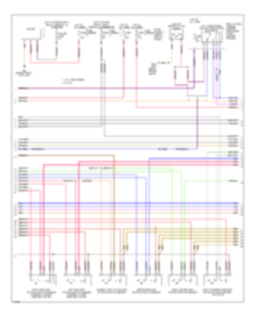
Automatic A/C Wiring Diagram, Comfort (2 of 4) for Audi Q7 Premium Plus 2014
 https://portal-diagnostov.com/license.html
Automotive Electricians Portal FZCO
Automotive Electricians Portal FZCO
https://portal-diagnostov.com/license.html
https://portal-diagnostov.com/license.html
Automotive Electricians Portal FZCO
Automotive Electricians Portal FZCOList of elements for Automatic A/C Wiring Diagram, Comfort (2 of 4) for Audi Q7 Premium Plus 2014:
- (3.0l turbo diesel) coolant circulation pump relay
- 10a
- 12a
- 3.0l sc
- 3.0l turbo diesel
- Coolant recirculation pump
- Cooler
- Cooler fuse 5a
- Defroster door motor & position sensor
- Fuse 10a
- Fuse 15a
- Fuse 30a
- Fuse 40a
- Fuse 5a
- Fuse carrier
- Fuse panel c (right end of dash)
- G62 (base of right "c" pillar)
- G640 (left side of engine compt)
- Hot at all times
- Indirect ventilation door motor & position sensor
- Left side vent motor & position sensor (integral to left side vent motor)
- Pnk
- Relay & fuse carrier (center instrument panel) (center of dash)
- Right center vent motor & position sensor
- Right side vent motor & position sensor (integral to right side vent motor)
- Right temperature door motor & potentiometer/ actuator
- T10c
Automatic A/C Wiring Diagram, Comfort (3 of 4) for Audi Q7 Premium Plus 2014
 https://portal-diagnostov.com/license.html
Automotive Electricians Portal FZCO
Automotive Electricians Portal FZCO
https://portal-diagnostov.com/license.html
https://portal-diagnostov.com/license.html
Automotive Electricians Portal FZCO
Automotive Electricians Portal FZCOList of elements for Automatic A/C Wiring Diagram, Comfort (3 of 4) for Audi Q7 Premium Plus 2014:
- (3.0l sc) auxiliary engine coolant pump relay
- (left front long member) g671
- (lower right front of engine compt) (3.0l sc) charge air cooling pump
- 10a
- 13a
- 19a
- 19c
- 19d
- 19e
- 3.0l sc
- 3.0l turbo diesel
- After-run coolant pump (left front of engine)
- Engine coolant shift-off valve relay (3.0l turbo diesel)
- Fuse 10a
- Fuse 15a
- Fuse 40a/ 60a
- Fuse 5a
- Fuse 60a/ 40a
- G609 (right plenum chamber)
- G645
- High pressure sensor (on a/c high pressure line)
- Hot at all times
- Left front seat temperature sensor (w/ auxiliary heater) (under driver's seat)
- Map controlled engine cooling thermostat (3.0l turbo diesel) (center front of engine)
- Pnk
- Relay & fuse panel (e-box) (left plenum chamber)
- Right front seat temperature sensor (w/ auxiliary heater) (under right front seat)
- Sunlight photo sensor (top of dash panel, between defroster vents)
- T10ab
- T10d
- T10m
- T6f
- T6g
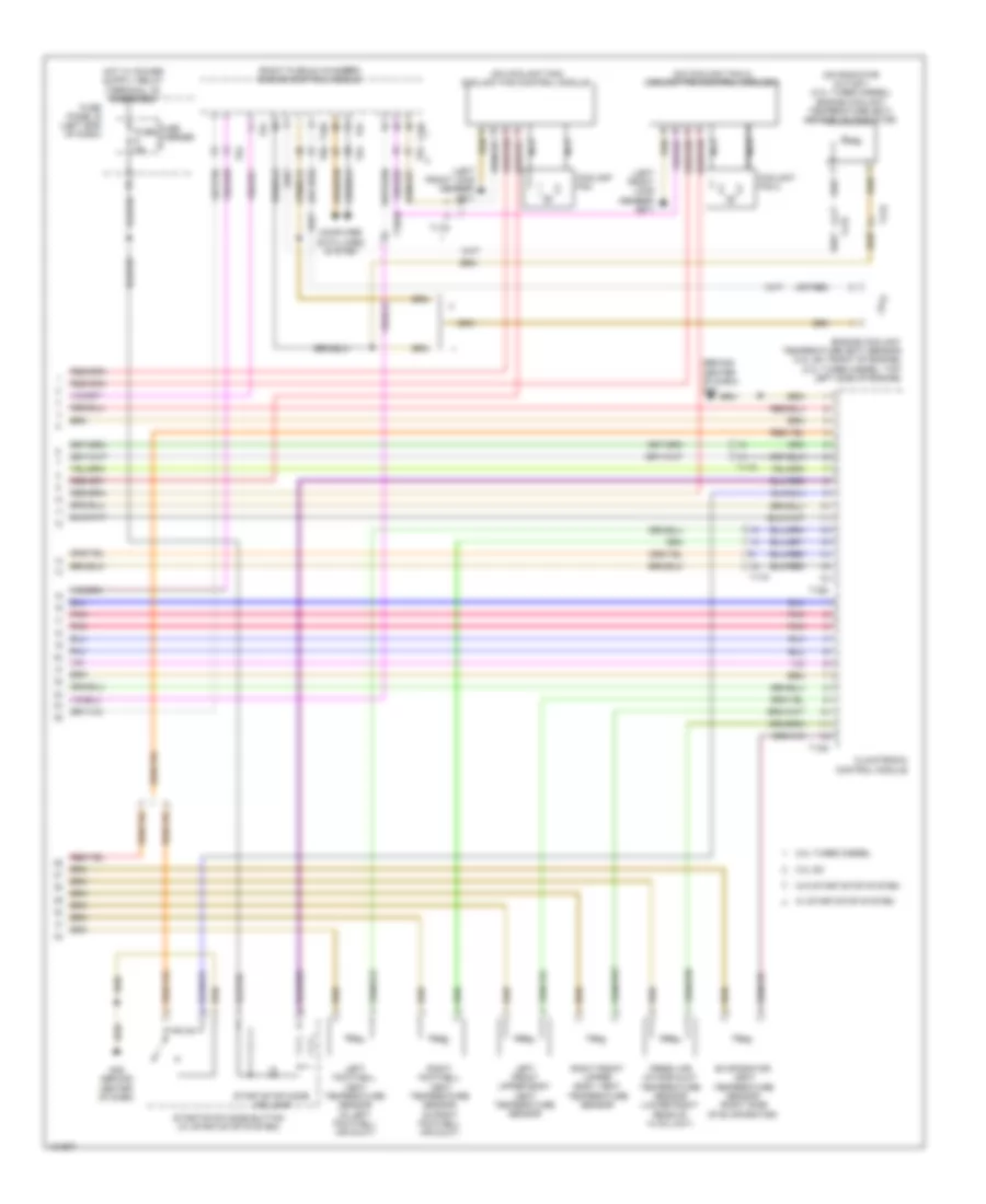
Automatic A/C Wiring Diagram, Comfort (4 of 4) for Audi Q7 Premium Plus 2014
 https://portal-diagnostov.com/license.html
Automotive Electricians Portal FZCO
Automotive Electricians Portal FZCO
https://portal-diagnostov.com/license.html
https://portal-diagnostov.com/license.html
Automotive Electricians Portal FZCO
Automotive Electricians Portal FZCOList of elements for Automatic A/C Wiring Diagram, Comfort (4 of 4) for Audi Q7 Premium Plus 2014:
- (behind center of dash) g45
- (left front long member) g671
- (on coolant fan 2) coolant fan control module 2
- (on coolant fan) coolant fan control module
- (on radiator outlet) (3.0l turbo diesel) engine coolant temperature (ect) sensor (on radiator)
- (or red)
- (right plenum chamber) engine control module
- 3.0l sc
- 3.0l turbo diesel
- Climatronic control module
- Computer data lines system
- Coolant fan
- Coolant fan 2
- Engine coolant temperature (ect) sensor (3.0l sc: front of engine) (3.0l turbo diesel: top left side of engine)
- Evaporator vent temperature sensor (right side of evaporator)
- Fresh air intake duct temperature sensor (lower right rear of hvac unit)
- Fuse 5a
- Fuse carrier
- Fuse panel b (left end of dash)
- G45 (behind center of dash)
- Left footwell vent temperature sensor (in left footwell air duct)
- Left front upper body vent temperature sensor
- Nca
- Pnk
- Right footwell vent temperature sensor (in right footwell air duct)
- Right front upper body vent temperature sensor
- Start/stop mode button (w/ start/stop system)
- Start/stop mode ind lamp
- T105
- T10ab
- T12g
- T16d
- T17d
- T17k
- T60
- T91
- T94
- W/ start/stop system
- W/o start/stop system
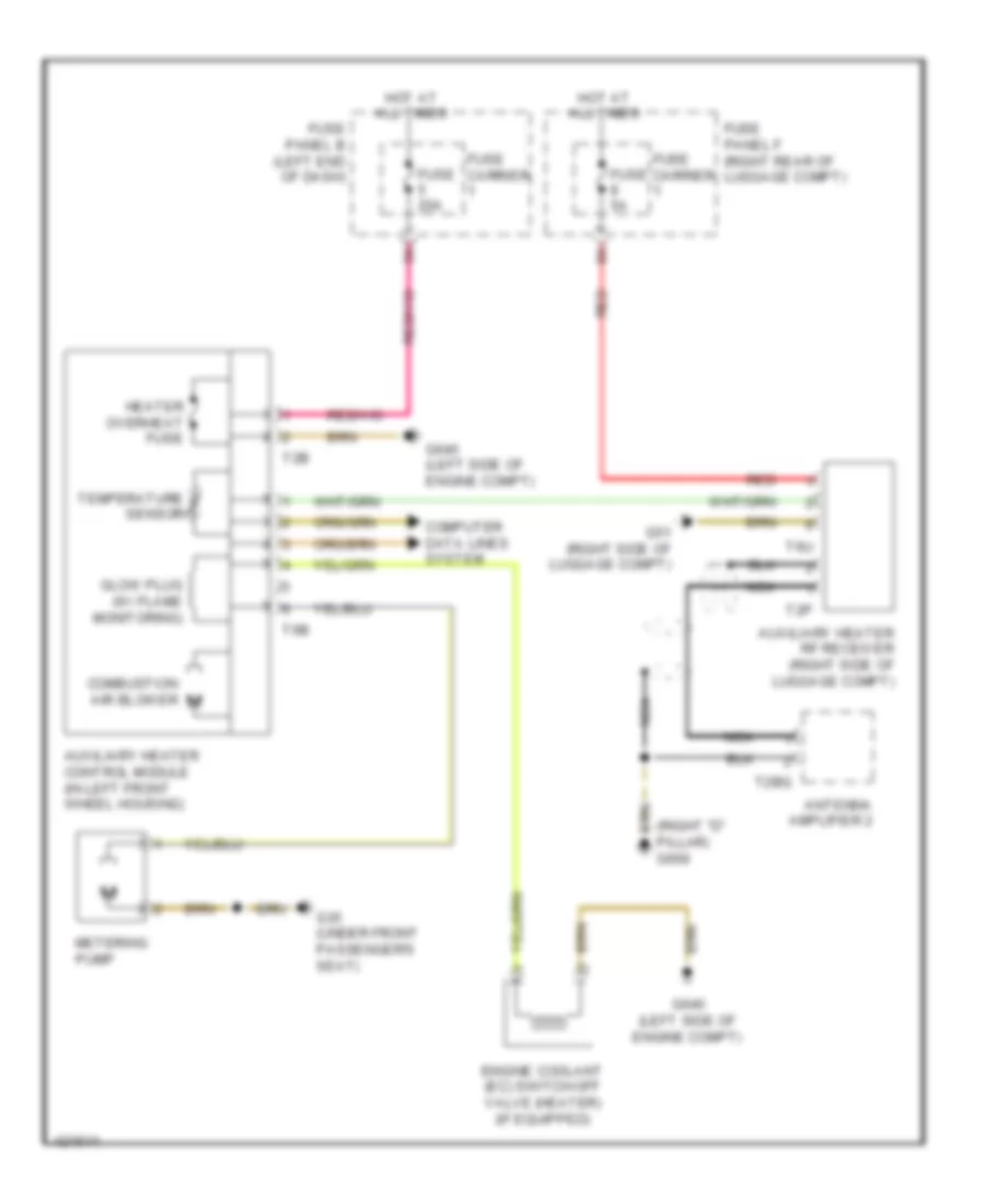
Auxiliary Heater Wiring Diagram for Audi Q7 Premium Plus 2014
 https://portal-diagnostov.com/license.html
Automotive Electricians Portal FZCO
Automotive Electricians Portal FZCO
https://portal-diagnostov.com/license.html
https://portal-diagnostov.com/license.html
Automotive Electricians Portal FZCO
Automotive Electricians Portal FZCOList of elements for Auxiliary Heater Wiring Diagram for Audi Q7 Premium Plus 2014:
- (right "d" pillar) g669
- Antenna amplifier 2
- Auxiliary heater control module (in left front wheel housing)
- Auxiliary heater rf receiver (right side of luggage compt)
- Combustion air blower
- Computer data lines system
- Engine coolant (ec) switch-off valve (heater) (if equipped)
- Fuse 20a
- Fuse 5a
- Fuse carrier
- Fuse panel b (left end of dash)
- Fuse panel f (right rear of luggage compt)
- G35 (under front passenger's seat)
- G51 (right side of luggage compt)
- G640 (left side of engine compt)
- Glow plug (w/ flame monitoring)
- Heater overheat fuse
- Hot at all times
- Metering pump
- Nca
- Red
- T2b
- T2bq
- T2p
- T6b
- T6u
- Temperature sensor
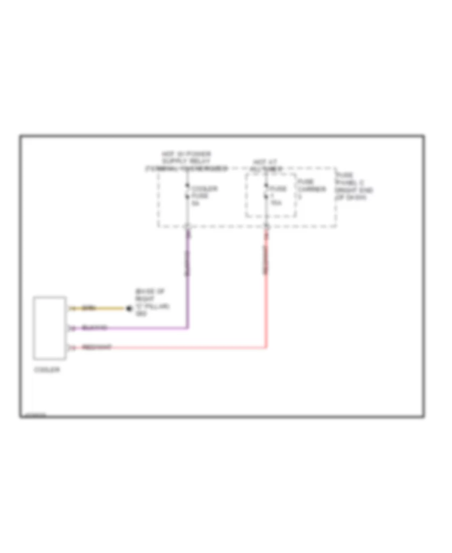
Cool Box Wiring Diagram for Audi Q7 Premium Plus 2014
 https://portal-diagnostov.com/license.html
Automotive Electricians Portal FZCO
Automotive Electricians Portal FZCO
https://portal-diagnostov.com/license.html
https://portal-diagnostov.com/license.html
Automotive Electricians Portal FZCO
Automotive Electricians Portal FZCOList of elements for Cool Box Wiring Diagram for Audi Q7 Premium Plus 2014:
- (base of right "c" pillar) g62
- Cooler
- Cooler fuse 5a
- Fuse 15a
- Fuse carrier
- Fuse panel c (right end of dash)
- Hot at all times
Rear A/C Wiring Diagram (1 of 2) for Audi Q7 Premium Plus 2014
 https://portal-diagnostov.com/license.html
Automotive Electricians Portal FZCO
Automotive Electricians Portal FZCO
https://portal-diagnostov.com/license.html
https://portal-diagnostov.com/license.html
Automotive Electricians Portal FZCO
Automotive Electricians Portal FZCOList of elements for Rear A/C Wiring Diagram (1 of 2) for Audi Q7 Premium Plus 2014:
- (left air duct of rear heating & a/c unit) left rear vent temperature sensor
- (right air duct of rear heating & a/c unit) right rear vent temperature sensor
- (under center console) g687
- 12a
- Computer data lines system
- Fuse 10a
- Fuse 20a
- Fuse 5a
- Fuse carrier
- Fuse panel c (right end of dash)
- Hot at all times
- Left "b" pillar/ footwell shut-off door motor & position sensor
- Left rear upper body vent motor & position sensor (left rear upper body vent motor: in left rear upper body vent duct)
- Rear a/c display control head
- Right "b" pillar/ footwell shut-off door motor & position sensor
- Right rear upper body vent motor & position sensor
- Seats system
- T12h
- T16h
- T17h
- T20h
- T3h
Rear A/C Wiring Diagram (2 of 2) for Audi Q7 Premium Plus 2014
 https://portal-diagnostov.com/license.html
Automotive Electricians Portal FZCO
Automotive Electricians Portal FZCO
https://portal-diagnostov.com/license.html
https://portal-diagnostov.com/license.html
Automotive Electricians Portal FZCO
Automotive Electricians Portal FZCOList of elements for Rear A/C Wiring Diagram (2 of 2) for Audi Q7 Premium Plus 2014:
- (base of left "c" pillar) g61
- Center instrument panel vent illumination bulb
- Computer data lines system
- Display unit
- Fresh air blower fuse 2 40a
- G43 (behind right kick panel)
- G44 (behind left kick panel)
- G67
- Hot at all times
- Instrument cluster control module
- Left instrument panel vent illumination bulb
- Left rear air door motor & position sensor
- Left rear temperature door motor & position sensor
- Rear center air vent illumination bulb
- Rear fresh air blower (on rear heating & a/c unit)
- Rear fresh air blower control module (right rear of rear heating & a/c unit)
- Red
- Relay & fuse carrier (center instrument panel) (center of dash)
- Right instrument panel vent illumination bulb
- Right rear air door motor & position sensor
- Right rear temperature door motor & position sensor
- Suppressor
- T12k
- T17h
- T2r
- T4u

 Čeština
 Dansk
Dansk Deutsch
 Ελληνικά
 English
 English
 Español
 Suomi
Suomi Français
 Français
 עברית
עברית Hrvatski
 Magyar
 Italiano
 日本語
日本語 한국어
한국어 Nederlands
 Polski
 Português
 Português
 Română
 Русский
 Slovenčina
 Slovenščina
 Svenska
 Türkçe
