COOLING FAN
Cooling Fan Wiring Diagram for Audi allroad Premium Plus 2013
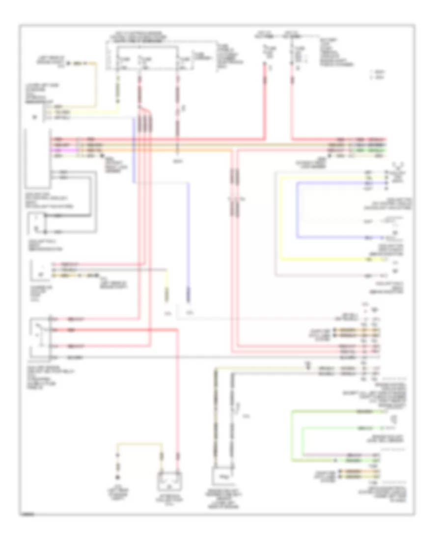
List of elements for Cooling Fan Wiring Diagram for Audi allroad Premium Plus 2013:
- (left rear of engine compt) g12
- (lower left side of engine) (2.0l) after run coolant pump
- (or red)
- 11a
- 16a
- 2.0l
- 2.ol
- 3.0l
- 400a
- 600w
- 800w
- After run coolant pump (3.0l)
- Auxiliary engine coolant (ec) pump relay (3.0l) (if equipped) (on relay/fuse panel b)
- Battery jump start terminal (middle of engine compt plenum chamber)
- Charge air cooling pump (3.0l)
- Computer data lines system
- Coolant fan (400w & 600w) (behind radiator)
- Coolant fan (800w)
- Coolant fan (fc) control module (on coolant fan motors)
- Coolant fan (fc) control module 2 (800w) (on coolant fan motors)
- Coolant fan 2 (600w) (behind radiator)
- Coolant fan 2 (800w) (behind radiator)
- Engine control module (ecm) (except 3.0l: left side of engine compt plenum chamber) (3.0l: right rear of engine compt)
- Engine coolant level (ecl) sensor
- Engine coolant temperature (ect) sensor (lower left rear of engine)
- Fuse 15a
- Fuse 40a
- Fuse 5a
- Fuse 60a 40a
- Fuse carrier 1
- Fuse panel b (in plenum chamber electronics box)
- G12 (left rear of engine compt)
- G685 (on right front long member)
- Hot at all times
- Nca
- Red
- T14f
- T16b
- T32b
- T5l
- T60
- T94
- Vehicle electrical system control module (under left side of dash)
 Čeština
 Dansk
Dansk Deutsch
 Ελληνικά
 English
 English
 Español
 Suomi
Suomi Français
 Français
 עברית
עברית Hrvatski
 Magyar
 Italiano
 日本語
日本語 한국어
한국어 Nederlands
 Polski
 Português
 Português
 Română
 Русский
 Slovenčina
 Slovenščina
 Svenska
 Türkçe
 中文 (中国)