ENGINE PERFORMANCE
2.0L TURBO
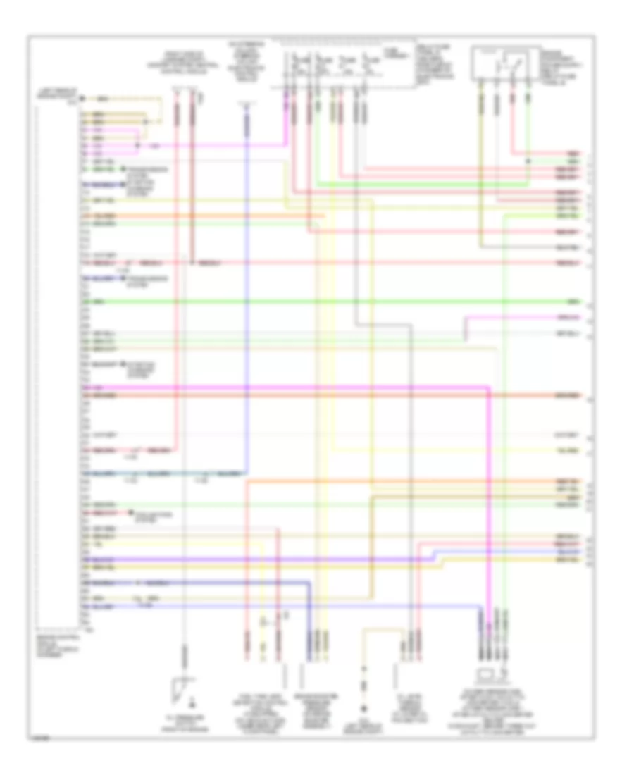
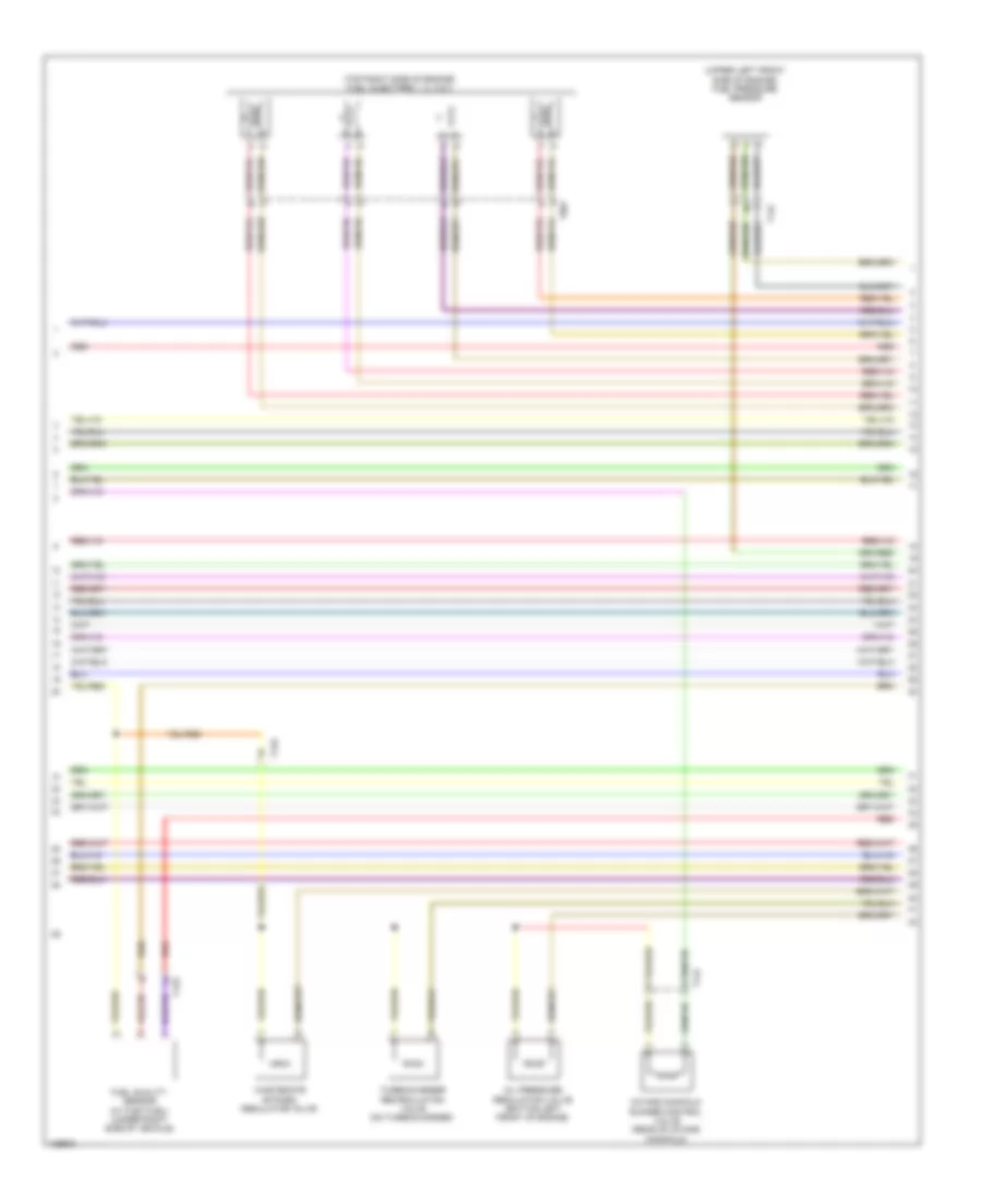
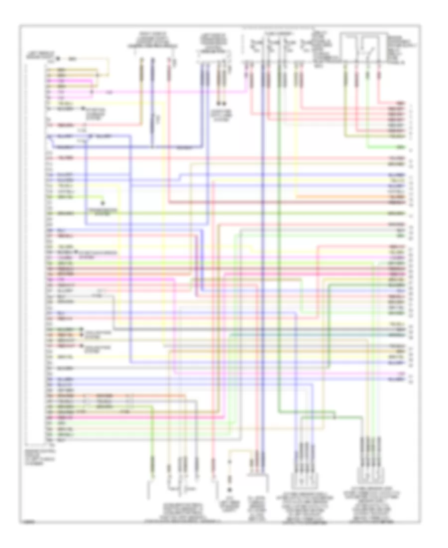
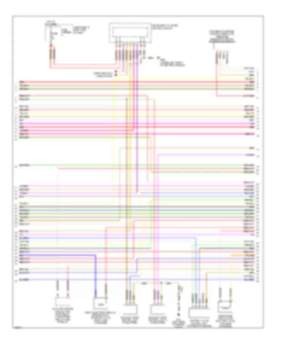
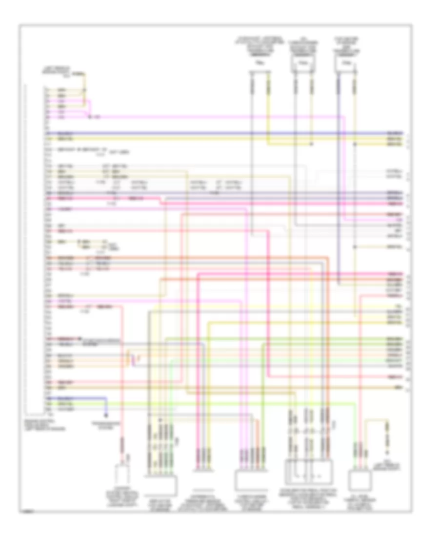
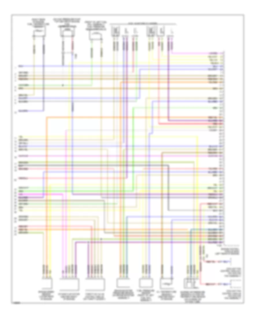
2.0L Turbo, Engine Performance Wiring Diagram (1 of 7) for Audi Q5 Hybrid Prestige 2014
 https://portal-diagnostov.com/license.html
Automotive Electricians Portal FZCO
Automotive Electricians Portal FZCO
https://portal-diagnostov.com/license.html
https://portal-diagnostov.com/license.html
Automotive Electricians Portal FZCO
Automotive Electricians Portal FZCO
List of elements for 2.0L Turbo, Engine Performance Wiring Diagram (1 of 7) for Audi Q5 Hybrid Prestige 2014:
- (left rear of engine compt) g12
- (on steering column) steering column electronics control module
- (right side of luggage compt) comfort system central control module
- 14a
- 17q
- Brake booster pressure sensor (on brake booster assembly)
- Cooling fans system
- Engine control module (in left plenum chamber)
- Fuel tank leak detection control module (if equipped) (on vehicle floor, under rear left floor panel)
- Fuse 15a
- Fuse 20a
- Fuse 5a
- Fuse carrier 1
- G12 (left rear of engine compt)
- Nca
- Oil level thermal sensor (in lower oil pan section)
- Oil pressure switch (front of engine)
- Oxygen sensor (o2s) after 3-way catalytic converter (twc) & oxygen sensor (o2s) 1 after catalytic converter heater (in exhaust, before three way catalytic converter)
- Red
- Relay/fuse panel b (driver's side plenum chamber on electronics box)
- Starting/ charging system
- System
- T17b
- T17q
- T17r
- T32d
- T94
- Transmissions
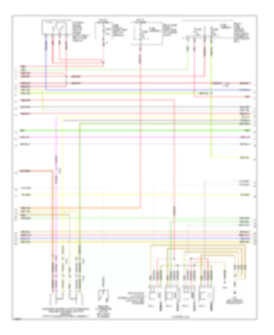
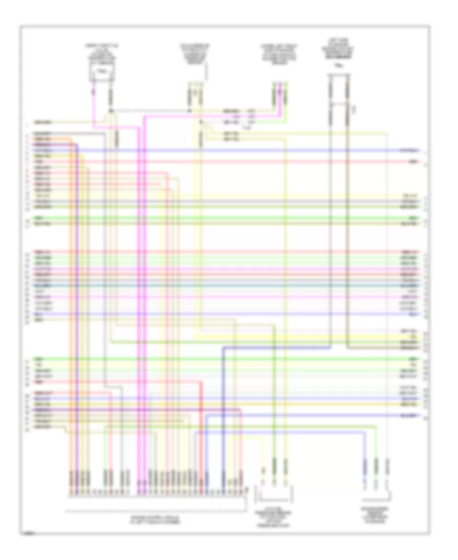
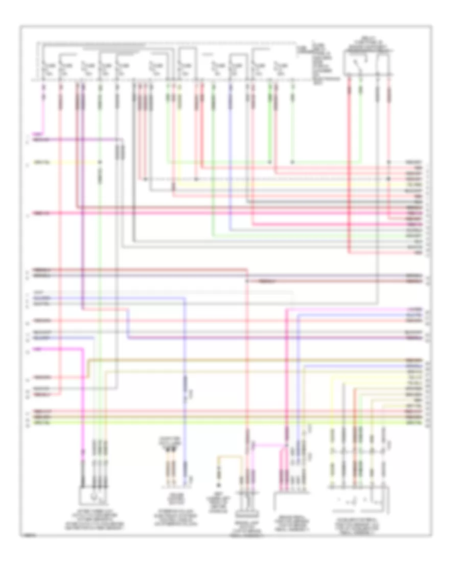
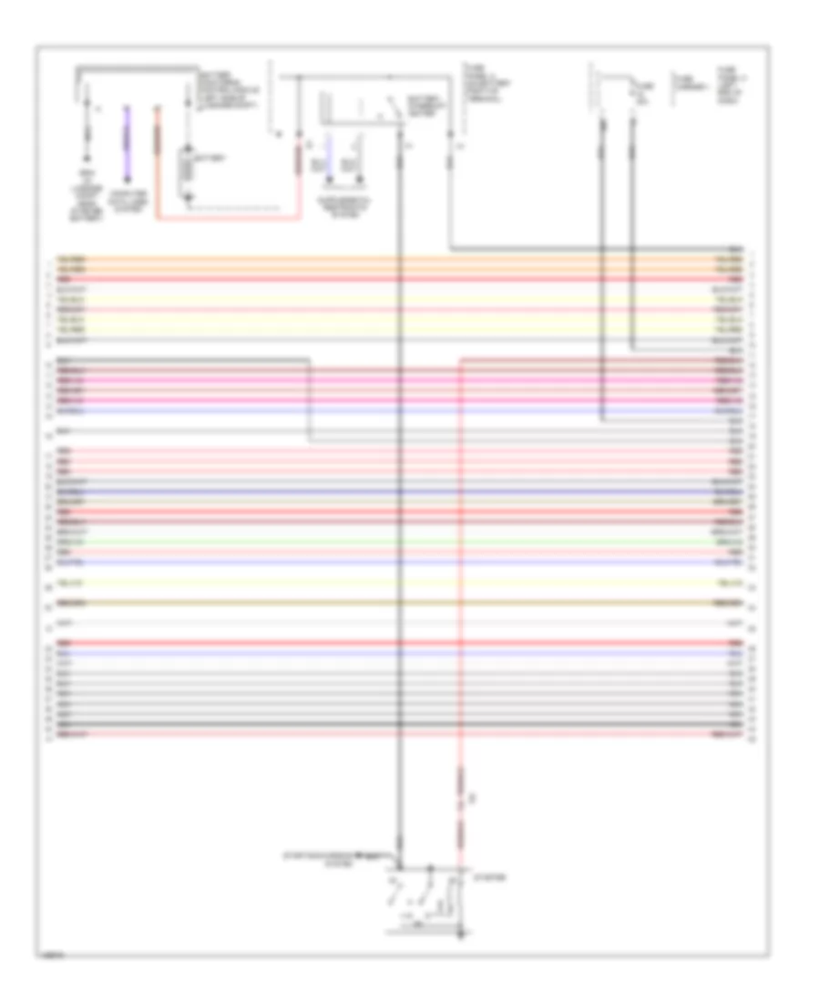
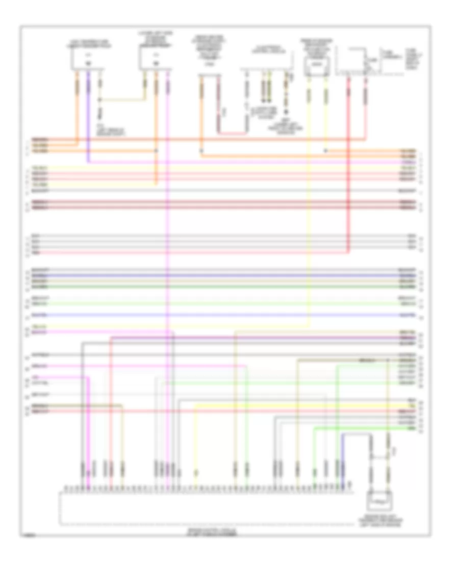
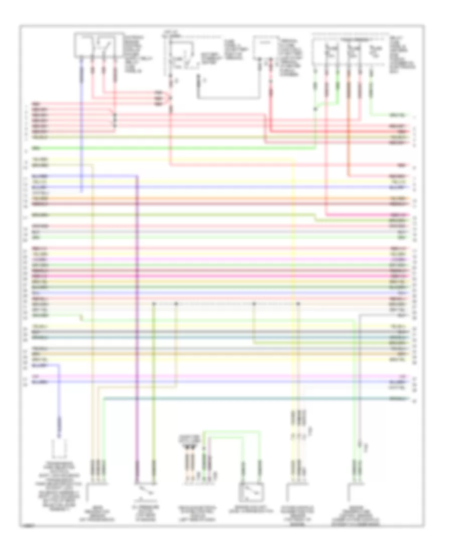
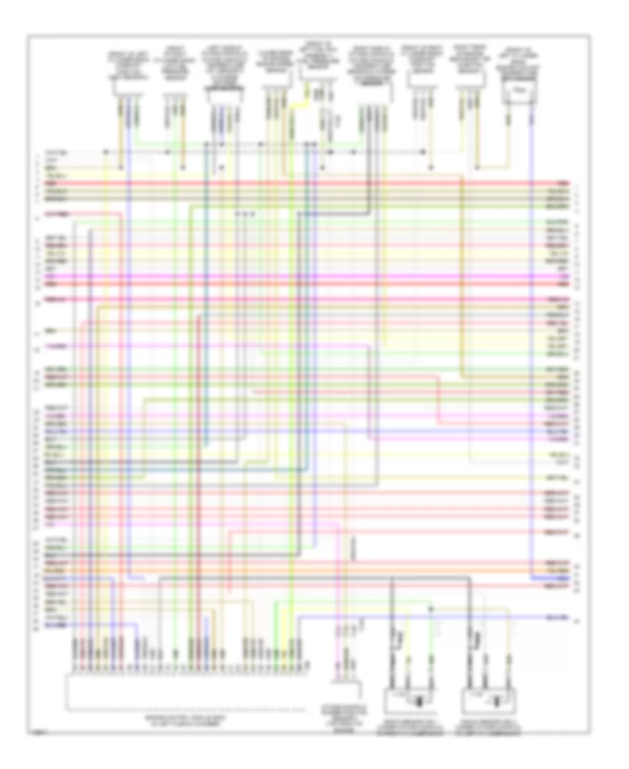
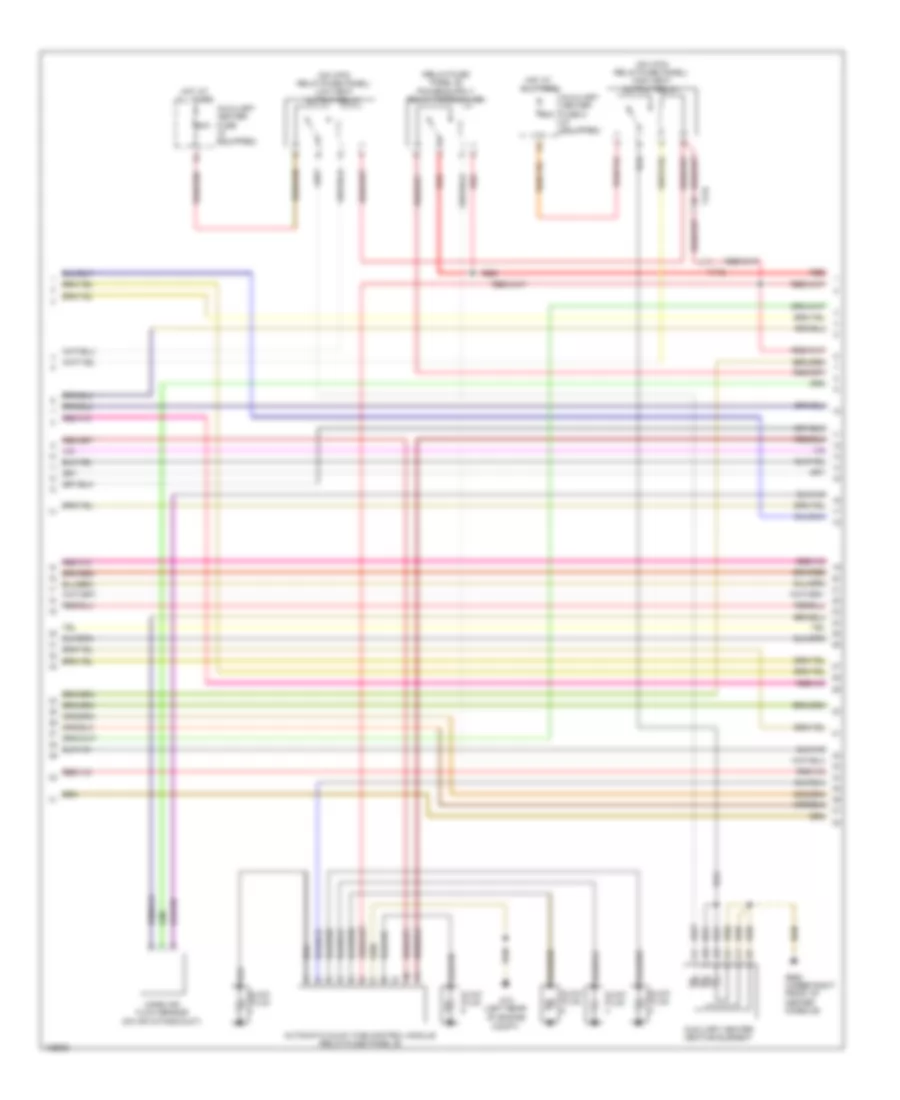
2.0L Turbo, Engine Performance Wiring Diagram (2 of 7) for Audi Q5 Hybrid Prestige 2014
 https://portal-diagnostov.com/license.html
Automotive Electricians Portal FZCO
Automotive Electricians Portal FZCO
https://portal-diagnostov.com/license.html
https://portal-diagnostov.com/license.html
Automotive Electricians Portal FZCO
Automotive Electricians Portal FZCOList of elements for 2.0L Turbo, Engine Performance Wiring Diagram (2 of 7) for Audi Q5 Hybrid Prestige 2014:
- 10a
- 12a
- Accelerator pedal position sensor & accelerator pedal position sensor 2 (top of accelerator pedal assembly)
- Coil 1
- Coil 2
- Coil 3
- Coil 4
- Fuse 10a
- Fuse 110a
- Fuse 15a
- Fuse 5a
- Fuse carrier 1
- Fuse carrier 2
- Fuse panel a (on battery positive terminal)
- G12 (left rear of engine compt)
- G18
- Hot at all times
- Ignition coils 1, 2, 3 & 4 w/ power output stage (top right side of engine)
- Nca
- Red
- Reduced oil pressure switch (left front of engine)
- Relay/ fuse panel b (driver's side plenum chamber on electronics box)
- Relay/fuse panel f (right side of luggage compt)
- T17e
- T17q
- T17r
- To spark plug
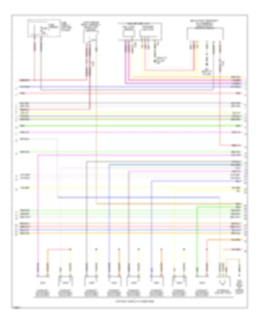
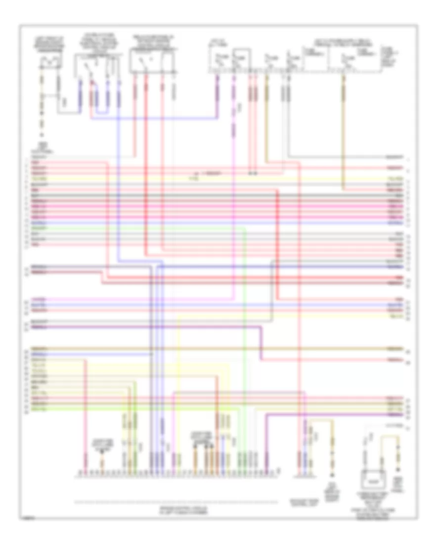
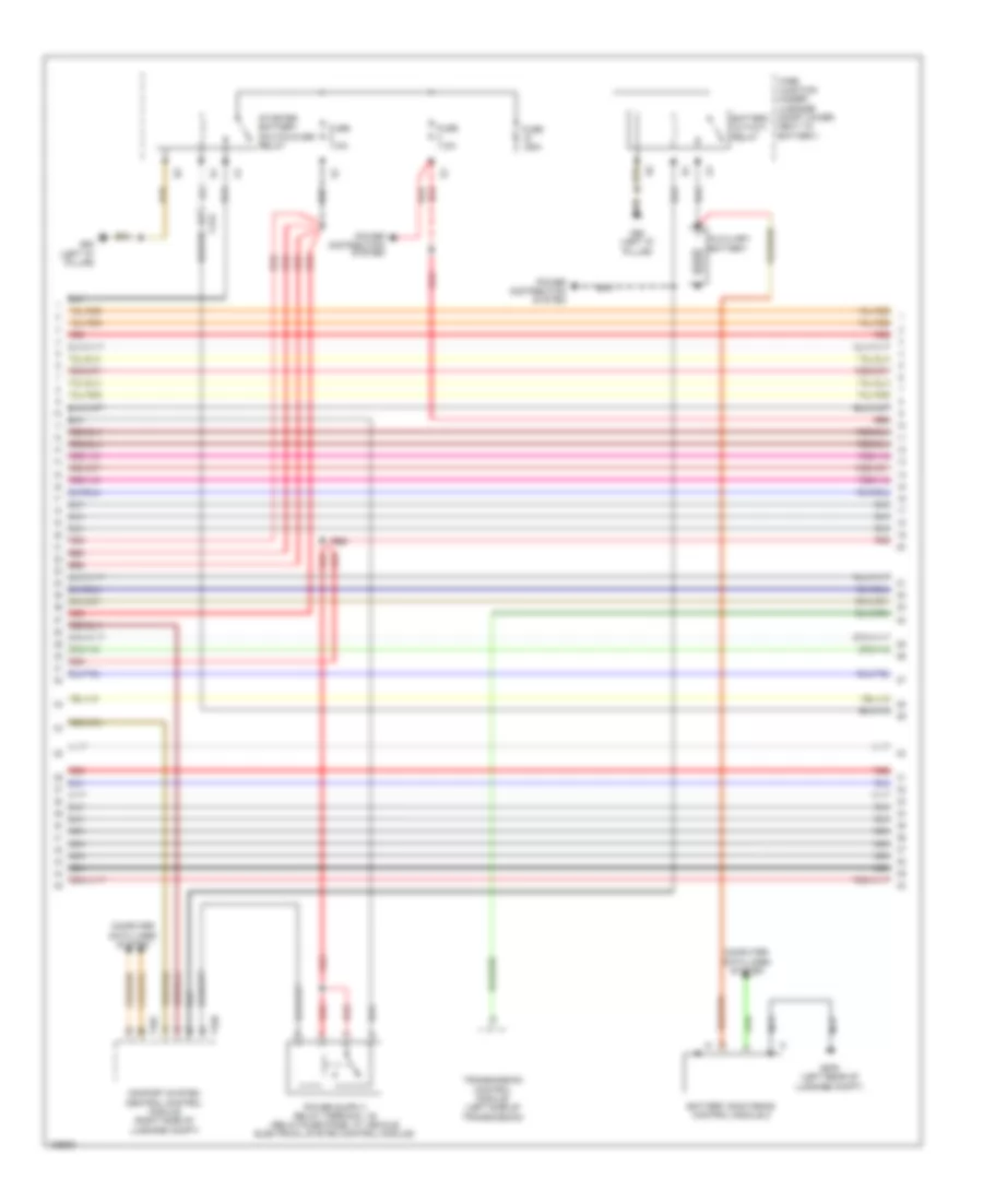
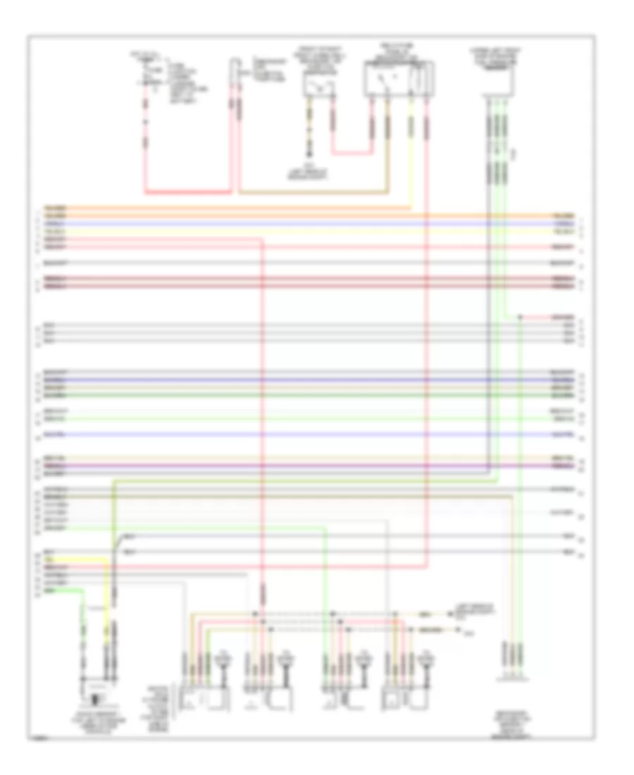
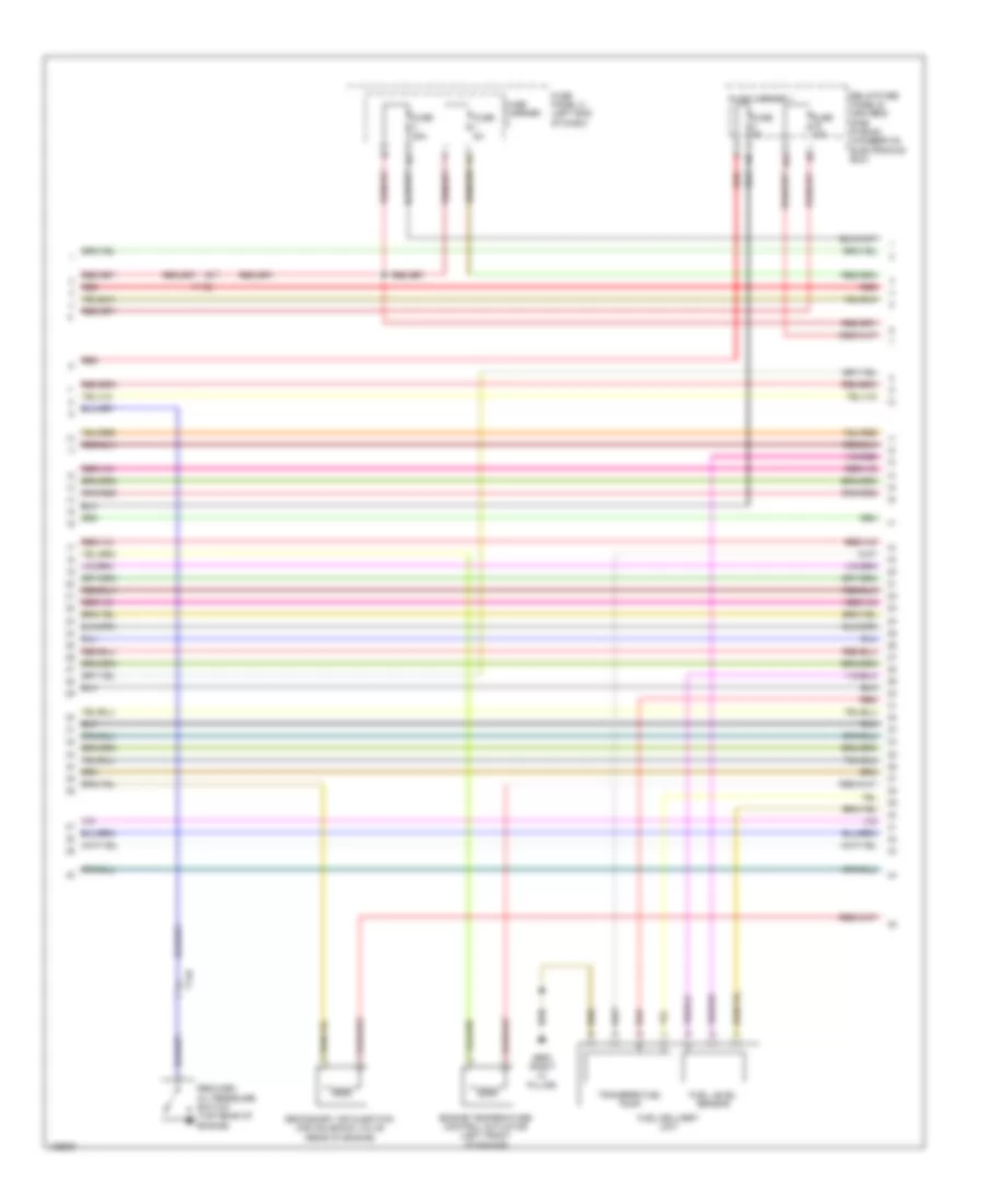
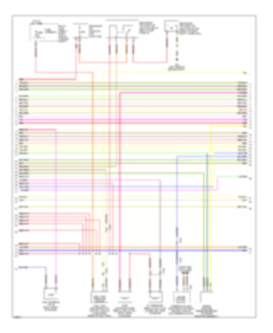
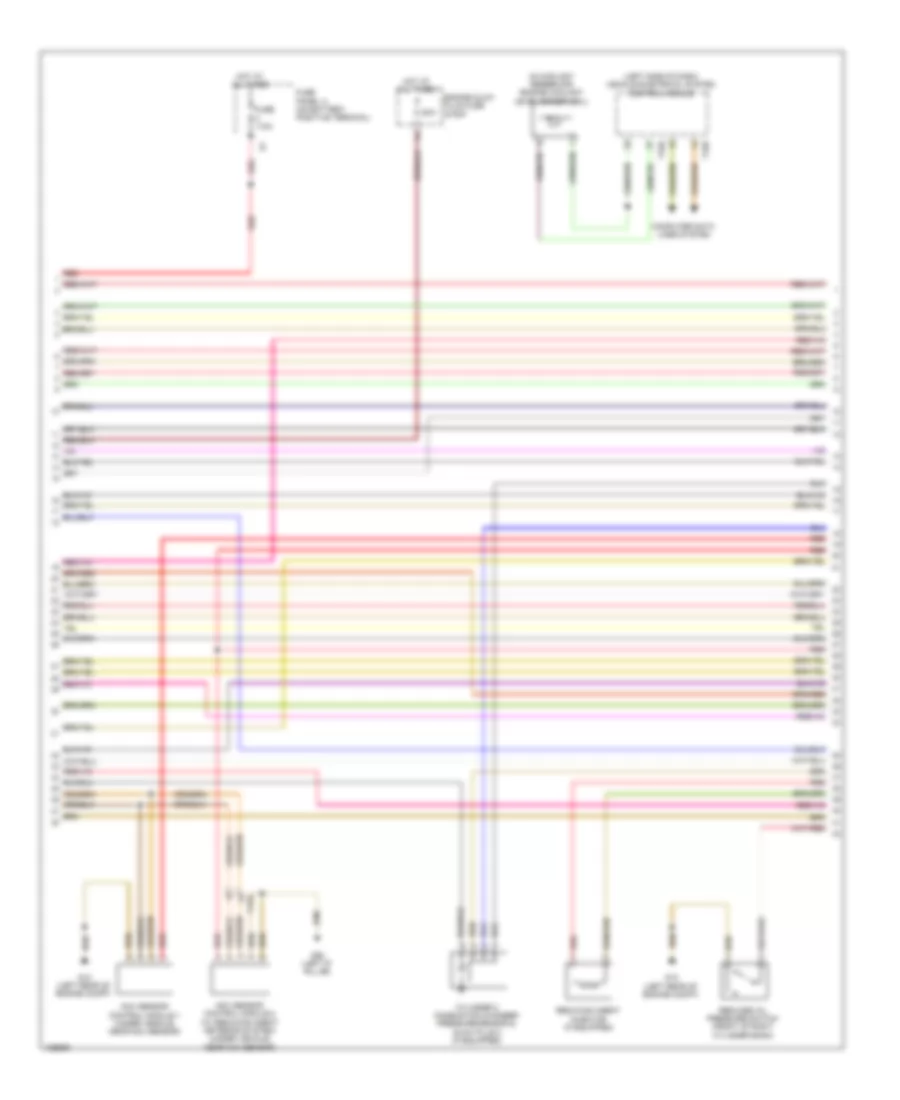
2.0L Turbo, Engine Performance Wiring Diagram (3 of 7) for Audi Q5 Hybrid Prestige 2014
 https://portal-diagnostov.com/license.html
Automotive Electricians Portal FZCO
Automotive Electricians Portal FZCO
https://portal-diagnostov.com/license.html
https://portal-diagnostov.com/license.html
Automotive Electricians Portal FZCO
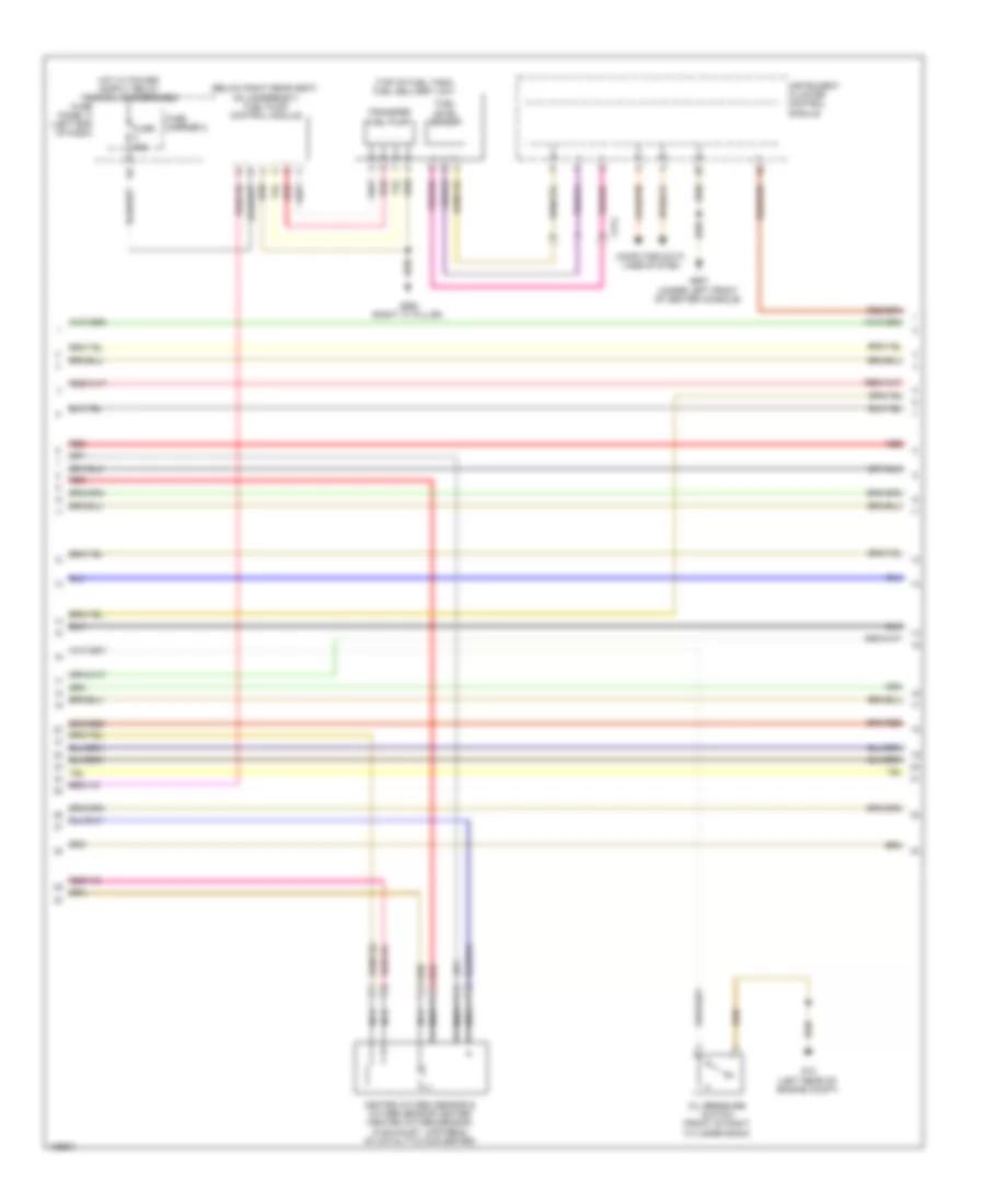
Automotive Electricians Portal FZCOList of elements for 2.0L Turbo, Engine Performance Wiring Diagram (3 of 7) for Audi Q5 Hybrid Prestige 2014:
- (below right rear seat, on underbody) fuel pump (fp) control module
- (right "d" pillar) g51
- (top of brake pedal assembly) brake lamp switch
- (top right side of cylinder head)
- After-run coolant pump
- Camshaft adjustment actuator 1
- Camshaft adjustment actuator 2
- Camshaft adjustment actuator 3
- Camshaft adjustment actuator 4
- Camshaft adjustment actuator 5
- Camshaft adjustment actuator 6
- Camshaft adjustment actuator 7
- Camshaft adjustment actuator 8
- Coil
- Fuel delivery unit
- Fuel level sensor
- Fuse 25a
- Fuse carrier
- Fuse panel c (left end of dash)
- G12 (left rear of engine compt)
- G51 (right "d" pillar)
- Red
- T17e
- T17q
- T3ak
- T4q
- Transfer fuel pump
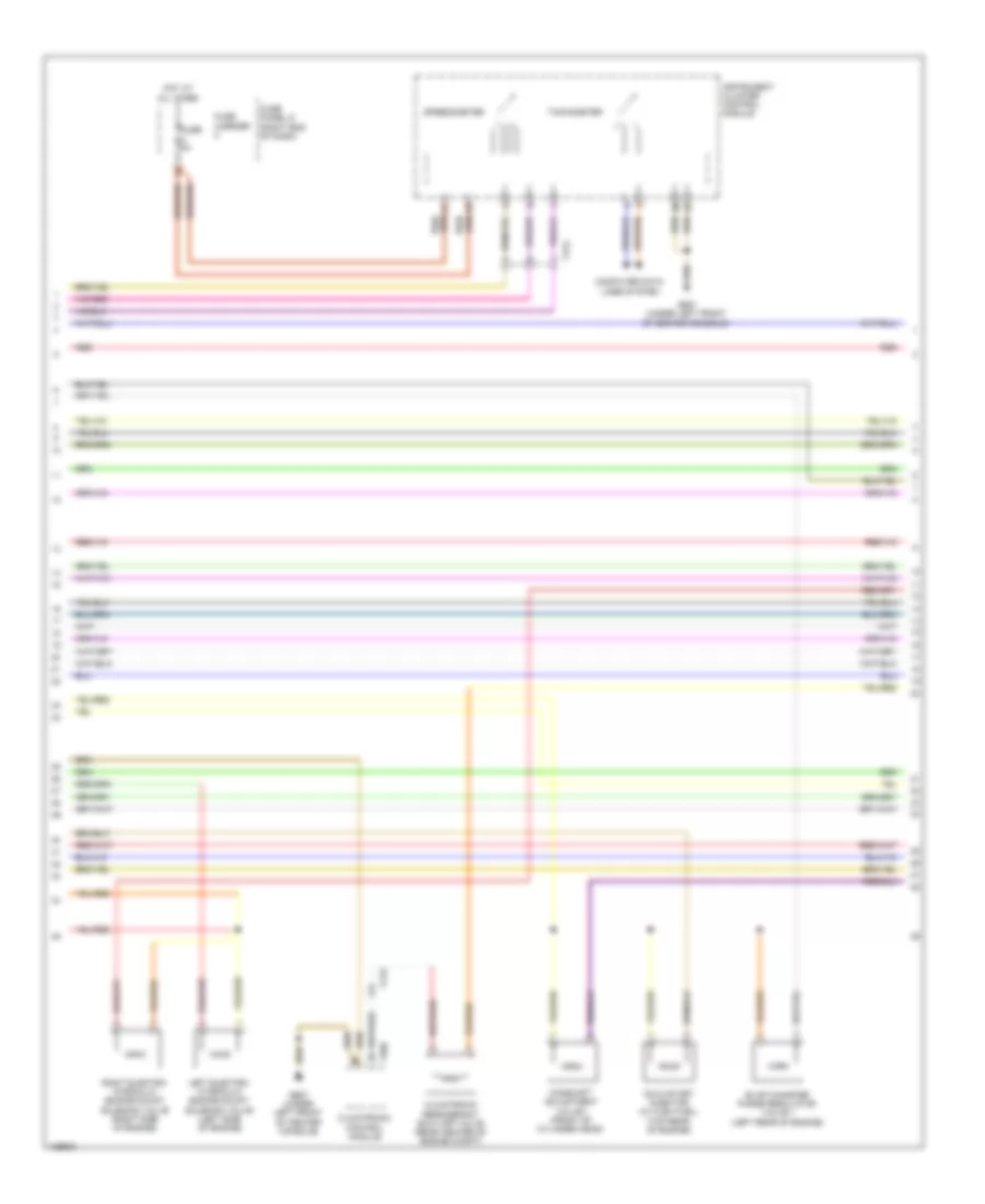
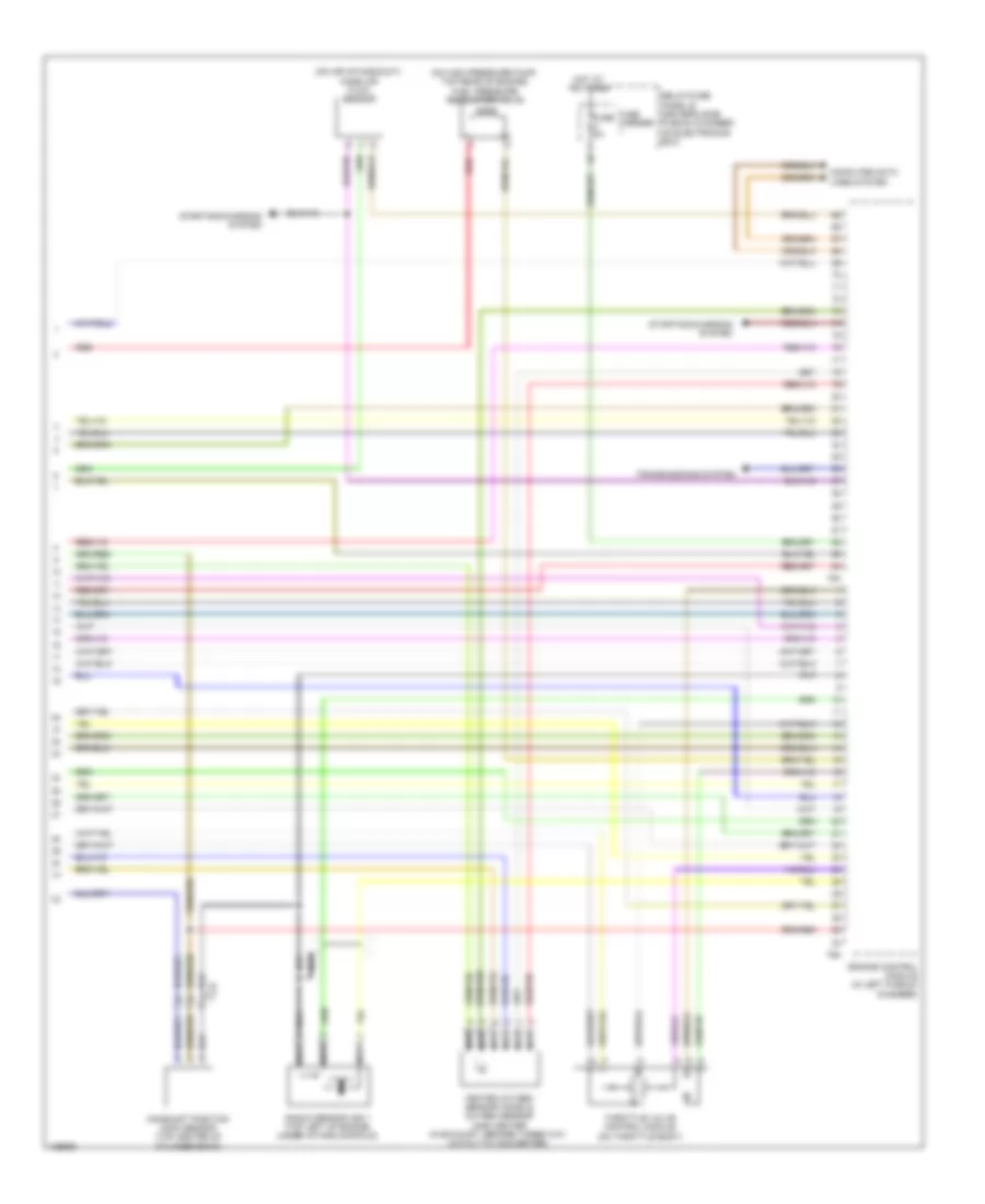
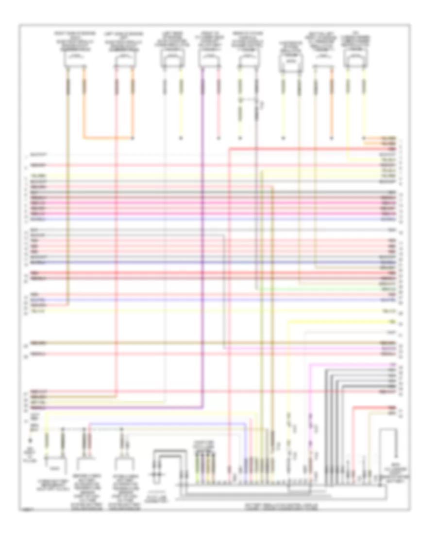
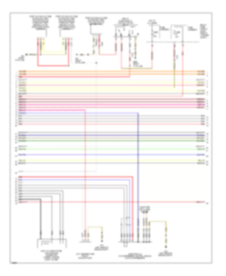
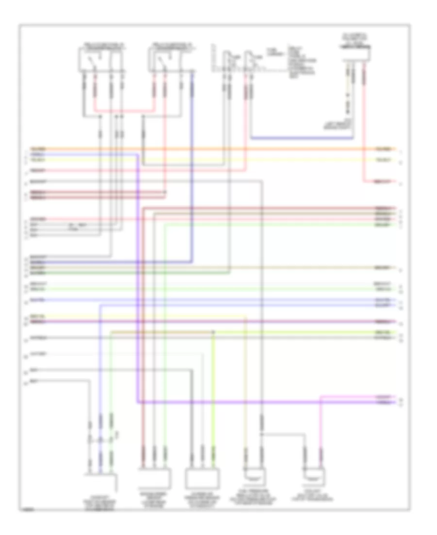
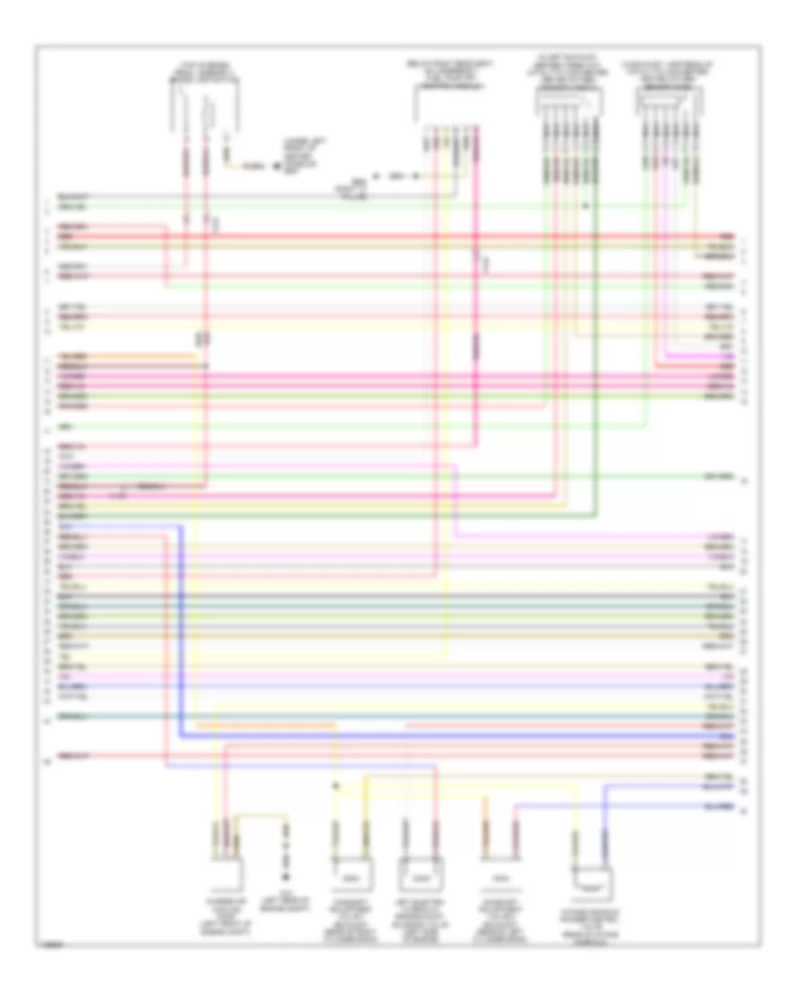
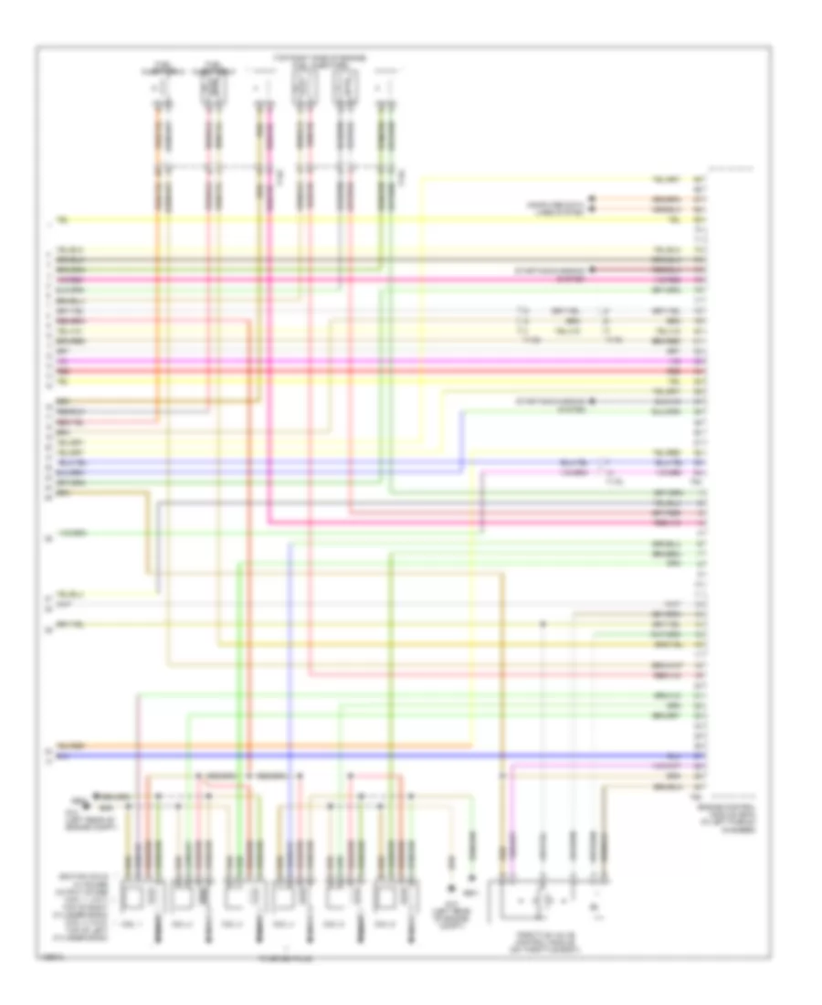
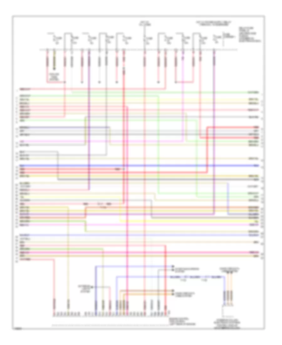
2.0L Turbo, Engine Performance Wiring Diagram (4 of 7) for Audi Q5 Hybrid Prestige 2014
 https://portal-diagnostov.com/license.html
Automotive Electricians Portal FZCO
Automotive Electricians Portal FZCO
https://portal-diagnostov.com/license.html
https://portal-diagnostov.com/license.html
Automotive Electricians Portal FZCO
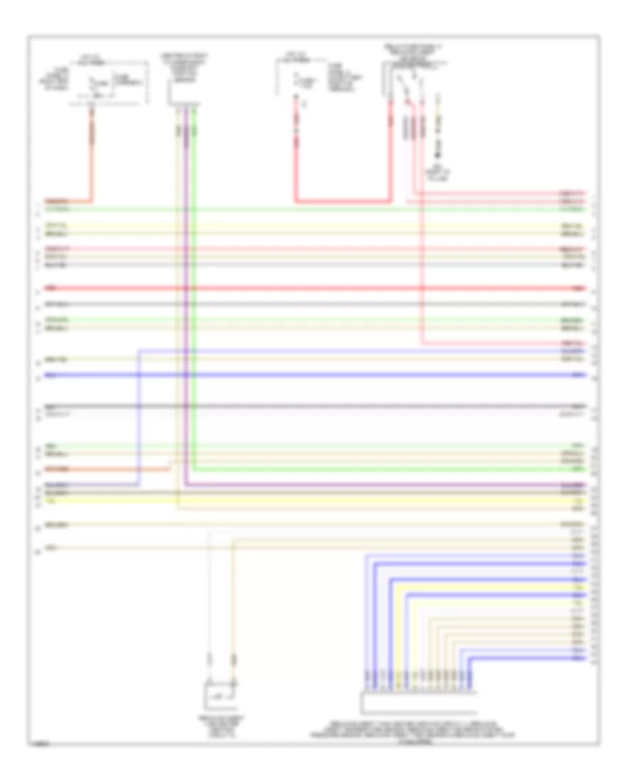
Automotive Electricians Portal FZCOList of elements for 2.0L Turbo, Engine Performance Wiring Diagram (4 of 7) for Audi Q5 Hybrid Prestige 2014:
- Camshaft adjustment valve 1 (front of cylinder head)
- Climatronic control module
- Climatronic refrigerant shut-off valve (rear center of engine compt)
- Cold start injector (w/ flex fuel) (top rear of engine)
- Computer data lines system
- Evap canister purge regulator valve 1 (left rear of engine)
- Fuse 5a
- Fuse carrier
- Fuse panel d (right end of dash)
- G687 (under left front of center console)
- Hot at all times
- Instrument cluster control module
- Left electro- hydraulic engine mount solenoid valve (left side of engine)
- Red
- Right electro- hydraulic engine mount solenoid valve (right side of engine)
- Speedometer
- T17b
- T17g
- T20e
- Tachometer
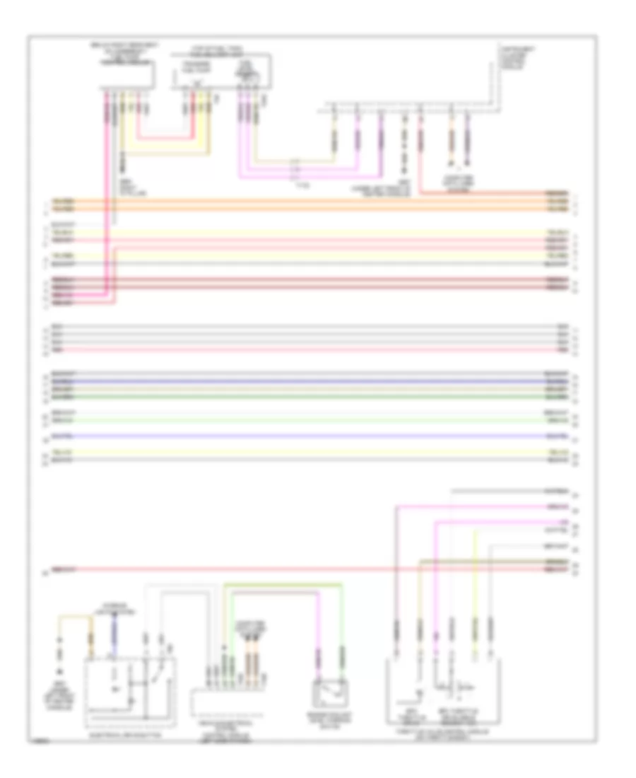
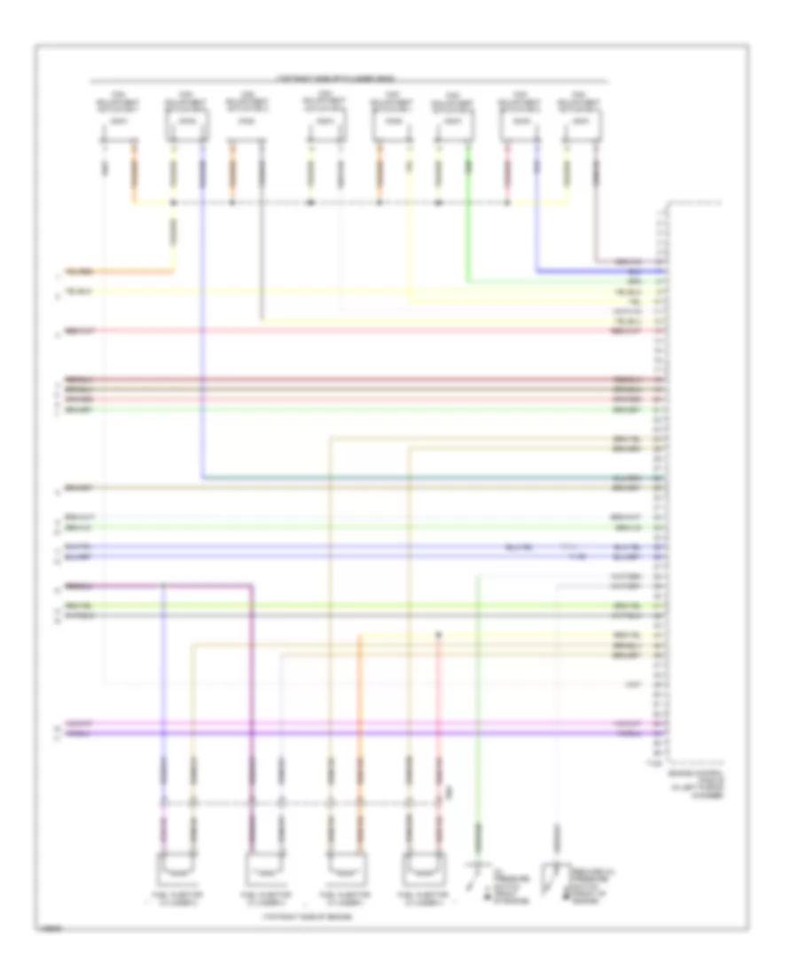
2.0L Turbo, Engine Performance Wiring Diagram (5 of 7) for Audi Q5 Hybrid Prestige 2014
 https://portal-diagnostov.com/license.html
Automotive Electricians Portal FZCO
Automotive Electricians Portal FZCO
https://portal-diagnostov.com/license.html
https://portal-diagnostov.com/license.html
Automotive Electricians Portal FZCO
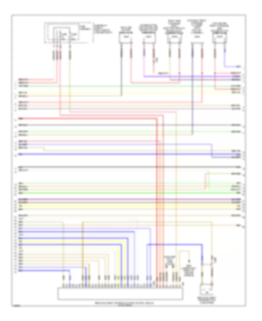
Automotive Electricians Portal FZCOList of elements for 2.0L Turbo, Engine Performance Wiring Diagram (5 of 7) for Audi Q5 Hybrid Prestige 2014:
- (top right side of engine) fuel injectors 1, 2, 3 & 4
- (upper left front side of engine) fuel pressure sensor
- Fuel quality sensor (w/ flex fuel) (under right side of vehicle)
- Intake manifold runner control valve (rear of intake manifold)
- Oil pressure regulation valve (bottom left front of engine)
- Red
- T14f
- T17q
- T8w
- Turbocharger recirculation valve (on turbocharger)
- Wastegate bypass regulator valve
2.0L Turbo, Engine Performance Wiring Diagram (6 of 7) for Audi Q5 Hybrid Prestige 2014
 https://portal-diagnostov.com/license.html
Automotive Electricians Portal FZCO
Automotive Electricians Portal FZCO
https://portal-diagnostov.com/license.html
https://portal-diagnostov.com/license.html
Automotive Electricians Portal FZCO
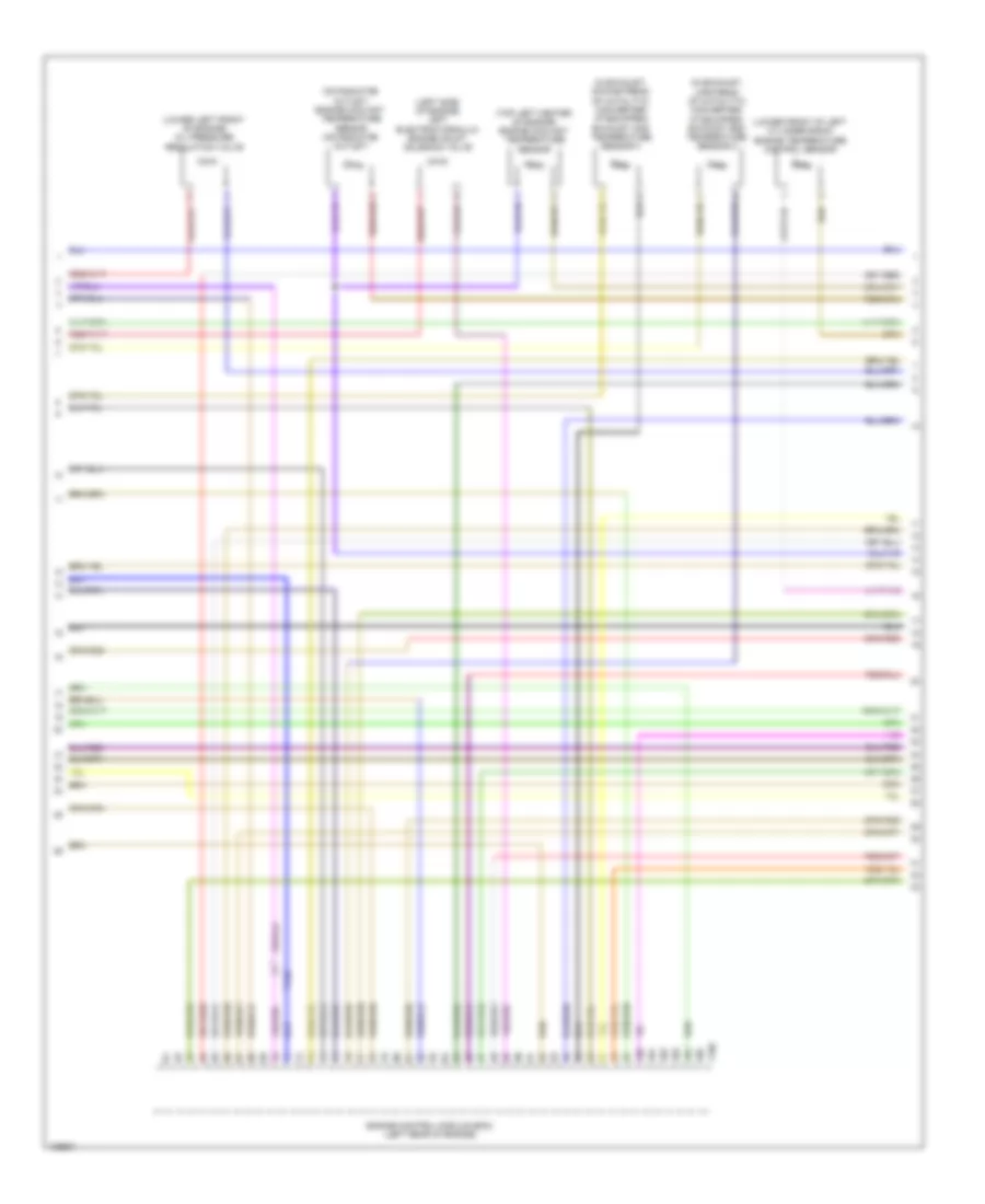
Automotive Electricians Portal FZCOList of elements for 2.0L Turbo, Engine Performance Wiring Diagram (6 of 7) for Audi Q5 Hybrid Prestige 2014:
- (left side of engine) engine coolant temperature (ect) sensor
- (near throttle valve) intake air temperature (iat) sensor
- (on charge air intake duct) charge air pressure sensor
- (upper left front side of engine) intake manifold runner position sensor
- Engine control module (in left plenum chamber)
- Engine speed sensor (lower rear of engine)
- Low fuel pressure sensor (w/ flex fuel) (on high pressure pump)
- Red
- T14f
- T60
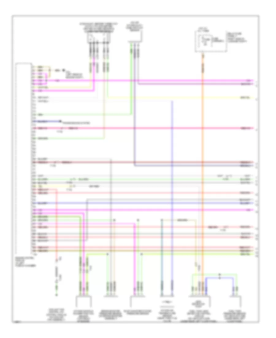
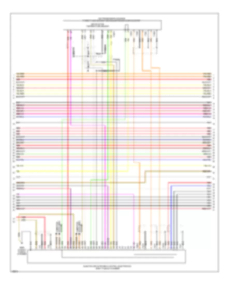
2.0L Turbo, Engine Performance Wiring Diagram (7 of 7) for Audi Q5 Hybrid Prestige 2014
 https://portal-diagnostov.com/license.html
Automotive Electricians Portal FZCO
Automotive Electricians Portal FZCO
https://portal-diagnostov.com/license.html
https://portal-diagnostov.com/license.html
Automotive Electricians Portal FZCO
Automotive Electricians Portal FZCOList of elements for 2.0L Turbo, Engine Performance Wiring Diagram (7 of 7) for Audi Q5 Hybrid Prestige 2014:
- (on air intake duct) mass air flow sensor
- (on high pressure pump, top rear of engine) fuel pressure regulator valve
- Camshaft position (cmp) sensor (top center of cylinder bank)
- Computer data lines system
- Engine control module (in left plenum chamber)
- Fuse 5a
- Fuse carrier
- Heated oxygen sensor (ho2s) & oxygen sensor (o2s) heater (in exhaust, before three way catalytic converter)
- Hot at all times
- Knock sensor (ks) 1 (top left of engine, under intake manifold)
- Nca
- Red
- Relay/fuse panel b (driver's side plenum chamber on electronics box)
- Starting/charging system
- T14f
- T60
- T94
- Throttle valve control module (on throttle body)
- Transmissions system
2.0L TURBO HYBRID
2.0L Turbo Hybrid, Engine Performance Wiring Diagram (1 of 13) for Audi Q5 Hybrid Prestige 2014
 https://portal-diagnostov.com/license.html
Automotive Electricians Portal FZCO
Automotive Electricians Portal FZCO
https://portal-diagnostov.com/license.html
https://portal-diagnostov.com/license.html
Automotive Electricians Portal FZCO
Automotive Electricians Portal FZCOList of elements for 2.0L Turbo Hybrid, Engine Performance Wiring Diagram (1 of 13) for Audi Q5 Hybrid Prestige 2014:
- (in exhaust, before three way catalytic converter) heated oxygen sensor & oxygen heater sensor
- (on air intake duct) mass air flow sensor
- 12a
- Brake booster pressure sensor (on brake booster assembly)
- Coolant fan control (fc) control module (on cooling fan assembly)
- Engine control module (in left plenum chamber)
- Evap canister system pressure sensor
- Fuel tank leak detection control module (on vehicle floor, under rear left floor panel)
- Fuel tank pressure sensor (on vehicle floor, under rear left floor panel)
- Fuse 5a
- Fuse carrier 2
- G12 (left rear of engine compt)
- Hot at all times
- Intake air temperature sensor (near throttle valve)
- Intake manifold runner position sensor (top front of engine)
- Leak detection pump
- Nca
- Relay/fuse panel f (right side of luggage compt)
- T14bi
- T14f
- T17e
- T17q
- T17r
- T5l
- T91
- Transmissions system
2.0L Turbo Hybrid, Engine Performance Wiring Diagram (2 of 13) for Audi Q5 Hybrid Prestige 2014
 https://portal-diagnostov.com/license.html
Automotive Electricians Portal FZCO
Automotive Electricians Portal FZCO
https://portal-diagnostov.com/license.html
https://portal-diagnostov.com/license.html
Automotive Electricians Portal FZCO
Automotive Electricians Portal FZCOList of elements for 2.0L Turbo Hybrid, Engine Performance Wiring Diagram (2 of 13) for Audi Q5 Hybrid Prestige 2014:
- 10a
- 13a
- 14a
- 17a
- Accelerator pedal position sensor 1 & 2 (top of accelerator pedal assembly)
- After three way catalytic converter oxygen sensor & after catalytic converter heater for oxygen sensor 1
- Brake lamp switch (top of brake pedal assembly)
- Brake pedal position sensor (top of brake pedal assembly)
- Computer data lines system
- Cruise control switch
- Fuse 10a
- Fuse 15a
- Fuse 20a
- Fuse 5a
- Fuse carrier
- Fuse/ relay panel b (driver's side plenum chamber on electronics box)
- G687 (under left front of center console)
- Nca
- Red
- Steering column electronic systems control module (on steering column)
- T16f
- T17b
- T17c
- T17e
- T17t
2.0L Turbo Hybrid, Engine Performance Wiring Diagram (3 of 13) for Audi Q5 Hybrid Prestige 2014
 https://portal-diagnostov.com/license.html
Automotive Electricians Portal FZCO
Automotive Electricians Portal FZCO
https://portal-diagnostov.com/license.html
https://portal-diagnostov.com/license.html
Automotive Electricians Portal FZCO
Automotive Electricians Portal FZCOList of elements for 2.0L Turbo Hybrid, Engine Performance Wiring Diagram (3 of 13) for Audi Q5 Hybrid Prestige 2014:
- (left front of engine compt) brake booster vacuum pump
- (on relay/fuse panel w/ vehicle electrical system control module) vacuum pump relay
- Computer data lines system
- Engine control module (in left plenum chamber)
- Exhaust door control unit
- Fuse 25a
- Fuse 30a
- Fuse 5a
- Fuse carrier 1
- Fuse carrier 2
- Fuse panel c (left end of dash)
- G12 (left rear of engine compt)
- G639 (left kick panel)
- Hot at all times
- Hybrid battery refrigerant shut-off valve 1 (part of high-voltage system battery cooling module)
- Red
- T14l
- T17e
- T17q
- T17r
- T17t
- T2ek
- T91
2.0L Turbo Hybrid, Engine Performance Wiring Diagram (4 of 13) for Audi Q5 Hybrid Prestige 2014
 https://portal-diagnostov.com/license.html
Automotive Electricians Portal FZCO
Automotive Electricians Portal FZCO
https://portal-diagnostov.com/license.html
https://portal-diagnostov.com/license.html
Automotive Electricians Portal FZCO
Automotive Electricians Portal FZCOList of elements for 2.0L Turbo Hybrid, Engine Performance Wiring Diagram (4 of 13) for Audi Q5 Hybrid Prestige 2014:
- (bottom left front of engine) oil pressure regulation valve
- (front of cylinder head) camshaft adjustment valve 1
- (left rear of engine) evap canister purge regulator valve 1
- (left side of engine) left electrohydraulic engine mount solenoid valve
- (on turbocharger) turbocharger recirculation valve
- (rear of intake manifold) intake manifold runner control valve
- (right side of engine) right electrohydraulic engine mount solenoid valve
- After hybrid battery evaporator temperature sensor (part of high- voltage system battery cooling module)
- Battery regulation control module (under luggage compartment cover)
- Before hybrid battery evaporator temperature sensor (part of high- voltage system battery cooling module)
- Computer data lines system
- G51 (right "d" pillar)
- G675 (in luggage compt near starter battery)
- Hybrid battery refrigerant shut-off valve 2
- Nca
- Pilot line connector 1
- Red
- T14ax
- T14f
- T14l
- T17t
- T1b
- T1c
- T8ax
- Wastegate bypass regulator valve
2.0L Turbo Hybrid, Engine Performance Wiring Diagram (5 of 13) for Audi Q5 Hybrid Prestige 2014
 https://portal-diagnostov.com/license.html
Automotive Electricians Portal FZCO
Automotive Electricians Portal FZCO
https://portal-diagnostov.com/license.html
https://portal-diagnostov.com/license.html
Automotive Electricians Portal FZCO
Automotive Electricians Portal FZCOList of elements for 2.0L Turbo Hybrid, Engine Performance Wiring Diagram (5 of 13) for Audi Q5 Hybrid Prestige 2014:
- (on transmission housing) three-phase current drive/electro-drive drive motor
- Computer data lines system
- Drive motor temperature sensor
- Electric drive power & control electronics (right plenum chamber)
- G609 (in right plenum chamber)
- Nca
- Red
- System data lines computer
- T10vx
- T1bu
- T1bv
- T1bw
- T1cu
- T1cv
- T1cw
- T1e
- T1f
- T28jx
- T2vx
- T4jx
2.0L Turbo Hybrid, Engine Performance Wiring Diagram (6 of 13) for Audi Q5 Hybrid Prestige 2014
 https://portal-diagnostov.com/license.html
Automotive Electricians Portal FZCO
Automotive Electricians Portal FZCO
https://portal-diagnostov.com/license.html
https://portal-diagnostov.com/license.html
Automotive Electricians Portal FZCO
Automotive Electricians Portal FZCOList of elements for 2.0L Turbo Hybrid, Engine Performance Wiring Diagram (6 of 13) for Audi Q5 Hybrid Prestige 2014:
- 16a
- Battery
- Battery interrupt igniter
- Battery monitoring control module (left side of luggage compt) b
- Computer data lines system
- Fuse 40a
- Fuse carrier 1
- Fuse panel a (on battery positive terminal)
- Fuse panel c (left end of dash)
- G624 (in luggage compt near starter battery)
- Nca
- Red
- Starter
- Starting/charging system
- T5i
2.0L Turbo Hybrid, Engine Performance Wiring Diagram (7 of 13) for Audi Q5 Hybrid Prestige 2014
 https://portal-diagnostov.com/license.html
Automotive Electricians Portal FZCO
Automotive Electricians Portal FZCO
https://portal-diagnostov.com/license.html
https://portal-diagnostov.com/license.html
Automotive Electricians Portal FZCO
Automotive Electricians Portal FZCOList of elements for 2.0L Turbo Hybrid, Engine Performance Wiring Diagram (7 of 13) for Audi Q5 Hybrid Prestige 2014:
- Auxiliary battery
- Battery cut-out relay
- Battery monitoring control module 2
- Comfort system central control module (right side of luggage compt)
- Computer data lines system
- Fuse 110a
- Fuse 125a
- G50 (left "d" pillar)
- G676 (left rear of luggage compt)
- Nca
- Power distribution system
- Red
- Starter battery switch-over relay
- T17r
- T32c
- T32d
- Transmission control module (left side of transmission)
- Wire junction (under luggage compt cover, next to battery)
2.0L Turbo Hybrid, Engine Performance Wiring Diagram (8 of 13) for Audi Q5 Hybrid Prestige 2014
 https://portal-diagnostov.com/license.html
Automotive Electricians Portal FZCO
Automotive Electricians Portal FZCO
https://portal-diagnostov.com/license.html
https://portal-diagnostov.com/license.html
Automotive Electricians Portal FZCO
Automotive Electricians Portal FZCOList of elements for 2.0L Turbo Hybrid, Engine Performance Wiring Diagram (8 of 13) for Audi Q5 Hybrid Prestige 2014:
- (part of high-voltage system battery cooling module) battery fan 1
- (part of high-voltage system battery cooling module) hybrid battery recirculation door positioning motor 1
- (part of high-voltage system battery cooling module) hybrid battery recirculation door positioning motor 2
- (relay/ fuse panel f) fan activation relay
- 12a
- Computer data lines system
- Electrical & a/c compressor control module (on a/c compressor)
- Fuse
- Fuse 30a
- Fuse carrier 3
- Fuse carrier 5
- G12 (left rear of engine compt)
- G51 (right "d" pillar)
- G663 (right "c" pillar)
- High voltage system maintenance connector (under luggage compt cover)
- Hot at all times
- Low temperature circuit coolant pump
- N/a
- Nca
- Red
- Relay/ fuse panel f (right side of luggage compt)
- T14l
- T2ei
2.0L Turbo Hybrid, Engine Performance Wiring Diagram (9 of 13) for Audi Q5 Hybrid Prestige 2014
 https://portal-diagnostov.com/license.html
Automotive Electricians Portal FZCO
Automotive Electricians Portal FZCO
https://portal-diagnostov.com/license.html
https://portal-diagnostov.com/license.html
Automotive Electricians Portal FZCO
Automotive Electricians Portal FZCOList of elements for 2.0L Turbo Hybrid, Engine Performance Wiring Diagram (9 of 13) for Audi Q5 Hybrid Prestige 2014:
- (below right rear seat, on underbody) fuel pump control module
- (top of fuel tank) fuel delivery unit
- Computer data lines system
- Electrical drive button
- Engine coolant level warning switch
- Epc throttle drive
- Epc throttle drive angle sensor 1 & 2
- Fuel level sensor
- G663 (right "d" pillar)
- G687 (under left front of center console)
- Instrument cluster control module
- Interior lights system
- Red
- T16b
- T17g
- T32b
- T3ak
- T4q
- T8s
- Throttle valve control module (on throttle body)
- Transfer fuel pump
- Vehicle electrical system control module (left side of dash)
2.0L Turbo Hybrid, Engine Performance Wiring Diagram (10 of 13) for Audi Q5 Hybrid Prestige 2014
 https://portal-diagnostov.com/license.html
Automotive Electricians Portal FZCO
Automotive Electricians Portal FZCO
https://portal-diagnostov.com/license.html
https://portal-diagnostov.com/license.html
Automotive Electricians Portal FZCO
Automotive Electricians Portal FZCOList of elements for 2.0L Turbo Hybrid, Engine Performance Wiring Diagram (10 of 13) for Audi Q5 Hybrid Prestige 2014:
- (lower left side of engine) after-run coolant pump
- (rear center of engine compt) climatronic refrigerant shut-off valve
- (rear of engine) secondary air injection solenoid valve
- Climatronic control module
- Computer data lines system
- Engine control module (in left plenum chamber)
- Engine coolant temperature sensor (left side of engine)
- Fuse 5a
- Fuse carrier 2
- Fuse panel d (right end of dash)
- G12 (left rear of engine compt)
- G687 (under left front of center console)
- High temperature circuit coolant pump
- Red
- T105
- T14f
- T17b
- T17q
- T20e
2.0L Turbo Hybrid, Engine Performance Wiring Diagram (11 of 13) for Audi Q5 Hybrid Prestige 2014
 https://portal-diagnostov.com/license.html
Automotive Electricians Portal FZCO
Automotive Electricians Portal FZCO
https://portal-diagnostov.com/license.html
https://portal-diagnostov.com/license.html
Automotive Electricians Portal FZCO
Automotive Electricians Portal FZCOList of elements for 2.0L Turbo Hybrid, Engine Performance Wiring Diagram (11 of 13) for Audi Q5 Hybrid Prestige 2014:
- (front of right front wheelwell) secondary air injection pump motor
- (left rear of engine compt) g12
- (relay/fuse panel b) secondary air injection pump relay
- (upper left front side of engine) fuel pressure sensor
- 50a
- Fuse 200a
- G12 (left rear of engine compt)
- G15
- Hot at all times
- Ignition coils w/ power output stage (top right side of engine)
- Knock sensor 1 (top left of engine under intake manifold)
- Nca
- Red
- Secondary air injection pump fuse
- Secondary air injection sensor 1 (rear of engine compt)
- T14f
- To spark plug
- Wire junction (under luggage compt cover, next to battery)
2.0L Turbo Hybrid, Engine Performance Wiring Diagram (12 of 13) for Audi Q5 Hybrid Prestige 2014
 https://portal-diagnostov.com/license.html
Automotive Electricians Portal FZCO
Automotive Electricians Portal FZCO
https://portal-diagnostov.com/license.html
https://portal-diagnostov.com/license.html
Automotive Electricians Portal FZCO
Automotive Electricians Portal FZCOList of elements for 2.0L Turbo Hybrid, Engine Performance Wiring Diagram (12 of 13) for Audi Q5 Hybrid Prestige 2014:
- (in lower oil pan section) oil level thermal sensor
- (relay/fuse panel b) starter relay
- (relay/fuse panel b) starter relay 2
- 12a
- Camshaft position sensor (top center of cylinder bank)
- Charge air pressure sensor (on charge air intake duct)
- Coolant shut-off valve (top of transmission)
- Engine speed sensor (lower rear of engine)
- Fuel pressure regulator valve (on high pressure pump, top rear of engine)
- Fuse 5a
- Fuse carrier 1
- G12 (left rear of engine compt)
- Relay/ fuse panel b (driver's side plenum chamber on electronics box)
- T14f
- T17r
2.0L Turbo Hybrid, Engine Performance Wiring Diagram (13 of 13) for Audi Q5 Hybrid Prestige 2014
 https://portal-diagnostov.com/license.html
Automotive Electricians Portal FZCO
Automotive Electricians Portal FZCO
https://portal-diagnostov.com/license.html
https://portal-diagnostov.com/license.html
Automotive Electricians Portal FZCO
Automotive Electricians Portal FZCOList of elements for 2.0L Turbo Hybrid, Engine Performance Wiring Diagram (13 of 13) for Audi Q5 Hybrid Prestige 2014:
- (top right side of cylinder head)
- (top right side of engine)
- Cam adjustment actuator 1
- Cam adjustment actuator 2
- Cam adjustment actuator 3
- Cam adjustment actuator 4
- Cam adjustment actuator 5
- Cam adjustment actuator 6
- Cam adjustment actuator 7
- Cam adjustment actuator 8
- Engine control module (in left plenum chamber)
- Fuel injector cylinder 1
- Fuel injector cylinder 2
- Fuel injector cylinder 3
- Fuel injector cylinder 4
- Oil pressure switch (front of engine)
- Reduced oil pressure switch (front of engine)
- T105
- T17r
- T8w
3.0L SC
3.0L SC, Engine Performance Wiring Diagram (1 of 8) for Audi Q5 Hybrid Prestige 2014
 https://portal-diagnostov.com/license.html
Automotive Electricians Portal FZCO
Automotive Electricians Portal FZCO
https://portal-diagnostov.com/license.html
https://portal-diagnostov.com/license.html
Automotive Electricians Portal FZCO
Automotive Electricians Portal FZCOList of elements for 3.0L SC, Engine Performance Wiring Diagram (1 of 8) for Audi Q5 Hybrid Prestige 2014:
- (left rear of engine compt) g12
- (left side of transmission) transmission control module (tcm)
- (right side of luggage compt) comfort system central control module
- 17a
- Accelerator pedal position sensor 1 & accelerator pedal position (app) sensor 2 (top of accelerator pedal assembly)
- Computer data lines system
- Cooling fans system
- Engine control module (in left plenum chamber)
- Fuse 10a
- Fuse 15a
- Fuse 5a
- Fuse carrier 1
- G12 (left rear of engine compt)
- Nca
- Oil level thermal sensor (in lower oil pan section)
- Oxygen sensor (02s) 2 after catalytic converter (twc) & oxygen sensor (o2s) 2 after catalytic converter heater (in left exhaust, behind three way catalytic converter)
- Oxygen sensor (o2s) after three way catalytic converter (twc) & oxygen sensor (o2s) 1 after catalytic converter heater (in right exhaust, behind three way catalytic converter)
- Red
- Relay/ fuse panel b (driver's side plenum chamber on electronics box)
- Starting/ charging system
- Starting/charging system
- T14g
- T16r
- T17e
- T17q
- T17r
- T32d
- T94
- Transmissions system
3.0L SC, Engine Performance Wiring Diagram (2 of 8) for Audi Q5 Hybrid Prestige 2014
 https://portal-diagnostov.com/license.html
Automotive Electricians Portal FZCO
Automotive Electricians Portal FZCO
https://portal-diagnostov.com/license.html
https://portal-diagnostov.com/license.html
Automotive Electricians Portal FZCO
Automotive Electricians Portal FZCOList of elements for 3.0L SC, Engine Performance Wiring Diagram (2 of 8) for Audi Q5 Hybrid Prestige 2014:
- 10a
- 14a
- Battery interrupt igniter
- Computer data lines system
- Engine coolant level warning switch
- Engine temperature control sensor (under intake manifold, on right cylinder bank)
- Fuse 10a
- Fuse 110a
- Fuse 15a
- Fuse 20a
- Fuse carrier 1
- Fuse panel a (on battery positive terminal)
- Gear recognition sensor (on transmission)
- Hot at all times
- Intake manifold runner position sensor (top front of engine)
- Oil pressure switch (top rear of engine)
- Red
- Relay/ fuse panel b (driver's side plenum chamber on electronics box)
- T14g
- T16b
- T32b
- Terminal 30 wire junction 2 w/ battery jump start terminal (in center plenum chamber)
- Transmission park selector switch & shift lock solenoid (transmission park selector switch: on shift lock solenoid assembly) (shift lock solenoid: bottom of gear selector lever assembly)
- Vehicle electrical system control module (left side of dash)
3.0L SC, Engine Performance Wiring Diagram (3 of 8) for Audi Q5 Hybrid Prestige 2014
 https://portal-diagnostov.com/license.html
Automotive Electricians Portal FZCO
Automotive Electricians Portal FZCO
https://portal-diagnostov.com/license.html
https://portal-diagnostov.com/license.html
Automotive Electricians Portal FZCO
Automotive Electricians Portal FZCOList of elements for 3.0L SC, Engine Performance Wiring Diagram (3 of 8) for Audi Q5 Hybrid Prestige 2014:
- 16a
- Engine temperature control actuator (left front of engine)
- Fuel delivery unit
- Fuel level sensor
- Fuse 15a
- Fuse 25a
- Fuse 5a
- Fuse carrier
- Fuse carrier 1
- Fuse panel c (left end of dash)
- G663 (right "c" pillar)
- Red
- Reduced oil pressure switch (top rear of engine)
- Relay/fuse panel b (driver's side plenum chamber on electronics box)
- Secondary air injection (air) solenoid valve (rear of engine)
- T14e
- T17q
- Transfer fuel pump
3.0L SC, Engine Performance Wiring Diagram (4 of 8) for Audi Q5 Hybrid Prestige 2014
 https://portal-diagnostov.com/license.html
Automotive Electricians Portal FZCO
Automotive Electricians Portal FZCO
https://portal-diagnostov.com/license.html
https://portal-diagnostov.com/license.html
Automotive Electricians Portal FZCO
Automotive Electricians Portal FZCOList of elements for 3.0L SC, Engine Performance Wiring Diagram (4 of 8) for Audi Q5 Hybrid Prestige 2014:
- (below right rear seat, on underbody) fuel pump (fp) control module
- (in exhaust, upstream of catalytic converter) heated oxygen sensor (h02s)
- (in left exhaust, before three way catalytic converter) heated oxygen sensor (ho2s) 2
- (top of brake pedal assembly) brake lamp switch
- (under left front of center console) g687
- Camshaft adjustment valve 1 (exhaust) (rear of right cylinder bank)
- Camshaft adjustment valve 2 (exhaust) (rear of left cylinder bank)
- Charge air cooling pump (left front of engine compt)
- G12 (left rear of engine compt)
- G663 (right "c" pillar)
- Intake manifold runner control valve (rear of intake manifold)
- Left electro- hydraulic engine mount solenoid valve (left side of engine)
- Nca
- Red
- T17e
- T17q
- T17r
3.0L SC, Engine Performance Wiring Diagram (5 of 8) for Audi Q5 Hybrid Prestige 2014
 https://portal-diagnostov.com/license.html
Automotive Electricians Portal FZCO
Automotive Electricians Portal FZCO
https://portal-diagnostov.com/license.html
https://portal-diagnostov.com/license.html
Automotive Electricians Portal FZCO
Automotive Electricians Portal FZCOList of elements for 3.0L SC, Engine Performance Wiring Diagram (5 of 8) for Audi Q5 Hybrid Prestige 2014:
- (top rear of engine) manifold absolute pressure sensor/intake air temperature sensor
- Auxiliary engine coolant (ec) pump relay (if equipped) (relay/fuse panel b)
- Computer data lines system
- Control valve control unit (top rear of engine)
- Crankcase ventilation shut-off valve (top rear of engine)
- Exhaust door control unit (if equipped)
- Exhaust door control unit 2 (if equipped)
- Fuse 5a
- Fuse carrier
- Fuse panel d (right end of dash)
- G12 (left rear of engine compt)
- G687 (under left front of center console)
- Hot at all times
- Instrument cluster control module
- Red
- Right electrohydraulic engine mount solenoid valve (right side of engine)
- T17g
- T17q
3.0L SC, Engine Performance Wiring Diagram (6 of 8) for Audi Q5 Hybrid Prestige 2014
 https://portal-diagnostov.com/license.html
Automotive Electricians Portal FZCO
Automotive Electricians Portal FZCO
https://portal-diagnostov.com/license.html
https://portal-diagnostov.com/license.html
Automotive Electricians Portal FZCO
Automotive Electricians Portal FZCOList of elements for 3.0L SC, Engine Performance Wiring Diagram (6 of 8) for Audi Q5 Hybrid Prestige 2014:
- (front of left cylinder bank) camshaft position (cmp) sensor 2
- (front of left cylinder bank) engine coolant temperature (ect) sensor
- (front of left fuel rail assembly) fuel pressure sensor
- (front of right cylinder bank) camshaft position sensor
- (front of right cylinder bank) low fuel pressure sensor
- (left side of intake manifold) intake manifold temperature (iat) sensor 2 & charge air pres- sure sensor 2
- (lower rear of engine) engine speed sensor
- (right rear of engine) secondary air injection sensor 1
- (right side of intake manifold) intake manifold temperature sensor & charge air pressure sensor
- Engine control module (ecm) (in left plenum chamber)
- Intake manifold runner position sensor 2 (top front of engine)
- Knock sensor (ks) 1 (under intake manifold, on right cylinder bank)
- Knock sensor (ks) 2 (under intake manifold, on left cylinder bank)
- Nca
- Red
- T14e
- T14g
- T60
3.0L SC, Engine Performance Wiring Diagram (7 of 8) for Audi Q5 Hybrid Prestige 2014
 https://portal-diagnostov.com/license.html
Automotive Electricians Portal FZCO
Automotive Electricians Portal FZCO
https://portal-diagnostov.com/license.html
https://portal-diagnostov.com/license.html
Automotive Electricians Portal FZCO
Automotive Electricians Portal FZCOList of elements for 3.0L SC, Engine Performance Wiring Diagram (7 of 8) for Audi Q5 Hybrid Prestige 2014:
- 12a
- 50a
- Brake booster pressure sensor (on brake booster assembly)
- Computer data lines system
- Cruise control switch
- Evap canister purge regulator valve 1 (right rear of engine)
- Fuel metering valve (right front of engine)
- Fuel tank leak detection control module (if equipped) (rear of fuel tank)
- Fuel tank pressure sensor
- Fuse 5a
- Fuse carrier 2
- G12 (left rear of engine compt)
- Hot at all times
- Oil pressure regulation valve (lower left side of engine)
- Red
- Relay/ fuse panel f (right side of luggage compt)
- Secondary air injection (air) pump fuse
- Secondary air injection (air) pump motor (front of right front wheelwell)
- Secondary air injection (air) pump relay (relay/fuse panel b)
- Steering column electronic systems control module (on steering column)
- T14e
- T16f
- T17b
- T17q
3.0L SC, Engine Performance Wiring Diagram (8 of 8) for Audi Q5 Hybrid Prestige 2014
 https://portal-diagnostov.com/license.html
Automotive Electricians Portal FZCO
Automotive Electricians Portal FZCO
https://portal-diagnostov.com/license.html
https://portal-diagnostov.com/license.html
Automotive Electricians Portal FZCO
Automotive Electricians Portal FZCOList of elements for 3.0L SC, Engine Performance Wiring Diagram (8 of 8) for Audi Q5 Hybrid Prestige 2014:
- (top right side of engine) fuel injectors
- Coil 1
- Coil 2
- Coil 3
- Coil 4
- Coil 5
- Coil 6
- Computer data lines system
- Engine control module (ecm) (in left plenum chamber)
- Fuel injectors 5
- Fuel injectors 6
- G12 (left rear of engine compt)
- G600
- G601
- Ignition coils w/ power output stage (coil 1, 2 & 3: top of right cylinder bank) (coil 4, 5 & 6: top of left cylinder bank)
- Nca
- Red
- Starting/charging system
- T14e
- T14g
- T17e
- T17q
- T17r
- T60
- T94
- Throttle valve control module (on throttle body)
- To spark plug
3.0L TURBO DIESEL
3.0L Turbo Diesel, Engine Performance Wiring Diagram (1 of 9) for Audi Q5 Hybrid Prestige 2014
 https://portal-diagnostov.com/license.html
Automotive Electricians Portal FZCO
Automotive Electricians Portal FZCO
https://portal-diagnostov.com/license.html
https://portal-diagnostov.com/license.html
Automotive Electricians Portal FZCO
Automotive Electricians Portal FZCOList of elements for 3.0L Turbo Diesel, Engine Performance Wiring Diagram (1 of 9) for Audi Q5 Hybrid Prestige 2014:
- (in exhaust, upstream of catalytic converter) exhaust gas temperature sensor 3
- (left rear of engine compt) g12
- (not used)
- (on turbocharger) exhaust gas temperature sensor 1
- (top center of engine) egr temperature sensor
- Accelerator pedal position sensor & accelerator pedal position sensor 2 (top of accelerator pedal assembly)
- Comfort system central control module (right side of luggage compt)
- Differential pressure sensor (in exhaust, upstream of catalytic converter)
- Egr motor (top center of engine)
- Engine control module (ecm) (left rear of engine)
- G12 (left rear of engine compt)
- Oil level thermal sensor (in lower oil pan section)
- Starting/charging system
- T10d
- T17b
- T17e
- T17q
- T17r
- T17t
- T32d
- T91
- Transmissions system
- Turbocharger control module 1 (top center of engine)
3.0L Turbo Diesel, Engine Performance Wiring Diagram (2 of 9) for Audi Q5 Hybrid Prestige 2014
 https://portal-diagnostov.com/license.html
Automotive Electricians Portal FZCO
Automotive Electricians Portal FZCO
https://portal-diagnostov.com/license.html
https://portal-diagnostov.com/license.html
Automotive Electricians Portal FZCO
Automotive Electricians Portal FZCOList of elements for 3.0L Turbo Diesel, Engine Performance Wiring Diagram (2 of 9) for Audi Q5 Hybrid Prestige 2014:
- (on 3-pin relay/fuse panel) high heat output relay
- (on 3-pin relay/fuse panel) low heat output relay
- 40a
- 60a
- Automatic glow time control module (relay/fuse panel b)
- Auxiliary heater fuse (if equipped)
- Auxiliary heater fuse 2 (if equipped)
- Auxiliary heater heating element
- Compt)
- G12 (left rear of engine
- G688 (under right front of center console)
- Glow plug
- Hot at all times
- Mass air flow sensor (on air intake duct)
- Red
- T17b
- T17q
3.0L Turbo Diesel, Engine Performance Wiring Diagram (3 of 9) for Audi Q5 Hybrid Prestige 2014
 https://portal-diagnostov.com/license.html
Automotive Electricians Portal FZCO
Automotive Electricians Portal FZCO
https://portal-diagnostov.com/license.html
https://portal-diagnostov.com/license.html
Automotive Electricians Portal FZCO
Automotive Electricians Portal FZCOList of elements for 3.0L Turbo Diesel, Engine Performance Wiring Diagram (3 of 9) for Audi Q5 Hybrid Prestige 2014:
- (in coolant reservoir) engine coolant level sensor (ecl)
- (left side of dash) vehicle electrical system control module
- 80a
- Computer data lines system
- Cylinder 2 combustion chamber pressure sensor & glow plug 2 (if equipped)
- Engine glow plug fuse strip
- Fuse 110a
- Fuse panel a (on battery positive terminal)
- G12 (left rear of engine compt)
- G50 (left "d" pillar)
- Hot at all times
- Injector (if equipped)
- Nox sensor control module 1 (under vehicle, near nox sensor)
- Nox sensor control module 2 (w/ reducing agent metering system) (under vehicle, near nox sensor)
- Red
- Reduced oil pressure switch (front of right cylinder bank)
- Reducing agent
- T16b
- T17q
- T32b
3.0L Turbo Diesel, Engine Performance Wiring Diagram (4 of 9) for Audi Q5 Hybrid Prestige 2014
 https://portal-diagnostov.com/license.html
Automotive Electricians Portal FZCO
Automotive Electricians Portal FZCO
https://portal-diagnostov.com/license.html
https://portal-diagnostov.com/license.html
Automotive Electricians Portal FZCO
Automotive Electricians Portal FZCOList of elements for 3.0L Turbo Diesel, Engine Performance Wiring Diagram (4 of 9) for Audi Q5 Hybrid Prestige 2014:
- 10a
- 11a
- 16a
- Computer data lines system
- Cooling fans system
- Engine control module (ecm) (left rear of engine)
- Exterior lights system
- Fuse 10a
- Fuse 15a
- Fuse 5a
- Fuse carrier 1
- Hot at all times
- Red
- Relay/fuse panel b (driver's side plenum chamber on electronics box)
- Starting/charging system
- Steering column electronic systems control module (on steering column)
- T17b
- T17q
- T91
3.0L Turbo Diesel, Engine Performance Wiring Diagram (5 of 9) for Audi Q5 Hybrid Prestige 2014
 https://portal-diagnostov.com/license.html
Automotive Electricians Portal FZCO
Automotive Electricians Portal FZCO
https://portal-diagnostov.com/license.html
https://portal-diagnostov.com/license.html
Automotive Electricians Portal FZCO
Automotive Electricians Portal FZCOList of elements for 3.0L Turbo Diesel, Engine Performance Wiring Diagram (5 of 9) for Audi Q5 Hybrid Prestige 2014:
- (below right rear seat, on underbody) fuel pump control module
- (top of fuel tank) fuel delivery unit
- Computer data lines system
- Fuel level sensor
- Fuse 25a
- Fuse carrier 2
- Fuse panel c (left end of dash)
- G12 (left rear of engine compt)
- G663 (right "c" pillar)
- G687 (under left front of center console)
- Heated oxygen sensor & oxygen sensor heater (heated oxygen sensor: in exhaust, upstream of catalytic converter)
- Instrument cluster control module
- Nca
- Oil pressure switch (front of right cylinder bank)
- Red
- T17g
- Transfer fuel pump
3.0L Turbo Diesel, Engine Performance Wiring Diagram (6 of 9) for Audi Q5 Hybrid Prestige 2014
 https://portal-diagnostov.com/license.html
Automotive Electricians Portal FZCO
Automotive Electricians Portal FZCO
https://portal-diagnostov.com/license.html
https://portal-diagnostov.com/license.html
Automotive Electricians Portal FZCO
Automotive Electricians Portal FZCOList of elements for 3.0L Turbo Diesel, Engine Performance Wiring Diagram (6 of 9) for Audi Q5 Hybrid Prestige 2014:
- (center of right cylinder bank) camshaft position sensor
- (if equipped)
- (relay/fuse panel f) reducing agent metering system relay
- Fuse 1 110a
- Fuse 5a
- Fuse carrier 2
- Fuse panel a (on battery positive terminal)
- Fuse panel d (right end of dash)
- G51 (right "d" pillar)
- Hot at all times
- Red
- Reducing agent line heater (heating circuit 2)
- Reducing agent tank heater (heating circuit 1), reducing agent temperature sensor, reducing agent metering system pressure sensor, reducing agent tank sensor & reducing agent pump
3.0L Turbo Diesel, Engine Performance Wiring Diagram (7 of 9) for Audi Q5 Hybrid Prestige 2014
 https://portal-diagnostov.com/license.html
Automotive Electricians Portal FZCO
Automotive Electricians Portal FZCO
https://portal-diagnostov.com/license.html
https://portal-diagnostov.com/license.html
Automotive Electricians Portal FZCO
Automotive Electricians Portal FZCOList of elements for 3.0L Turbo Diesel, Engine Performance Wiring Diagram (7 of 9) for Audi Q5 Hybrid Prestige 2014:
- (on egr motor) map controlled engine cooling thermostat
- (right side of engine) right electrohydraulic engine mount solenoid valve
- (top center front of engine) egr cooler switch over valve
- (top right front of engine) cylinder head coolant valve
- 11a
- 12a
- Air filter bypass door valve
- Computer data lines system
- Fuse 10a
- Fuse 30a
- Fuse carrier 5
- Fuse/relay panel f (right side of luggage compt)
- G688 (under right front of center console)
- Red
- Reducing agent metering system control module (if equipped)
- Reducing agent transfer pump (if equipped)
- T10d
- T28a
- T2rm
- T8d
3.0L Turbo Diesel, Engine Performance Wiring Diagram (8 of 9) for Audi Q5 Hybrid Prestige 2014
 https://portal-diagnostov.com/license.html
Automotive Electricians Portal FZCO
Automotive Electricians Portal FZCO
https://portal-diagnostov.com/license.html
https://portal-diagnostov.com/license.html
Automotive Electricians Portal FZCO
Automotive Electricians Portal FZCOList of elements for 3.0L Turbo Diesel, Engine Performance Wiring Diagram (8 of 9) for Audi Q5 Hybrid Prestige 2014:
- (in exhaust, downstream of catalytic converter) (if equipped) exhaust gas temperature sensor 4
- (in exhaust, upstream of catalytic converter) (if equipped) exhaust gas temperature sensor 2
- (left side of engine) left electrohydraulic engine mount solenoid valve
- (lower front of left cylinder bank) engine temperature control sensor
- (lower left front of engine) oil pressure regulation valve
- (on radiator outlet) engine coolant temperature sensor (on radiator outlet)
- (top left center of engine) engine coolant temperature sensor
- Engine control module (ecm) (left rear of engine)
- T105
- T10d
3.0L Turbo Diesel, Engine Performance Wiring Diagram (9 of 9) for Audi Q5 Hybrid Prestige 2014
 https://portal-diagnostov.com/license.html
Automotive Electricians Portal FZCO
Automotive Electricians Portal FZCO
https://portal-diagnostov.com/license.html
https://portal-diagnostov.com/license.html
Automotive Electricians Portal FZCO
Automotive Electricians Portal FZCOList of elements for 3.0L Turbo Diesel, Engine Performance Wiring Diagram (9 of 9) for Audi Q5 Hybrid Prestige 2014:
- (front of left fuel rail assembly) fuel pressure regulator valve
- (on high pressure pump, top center of engine) fuel metering valve
- (right rear of engine) fuel temperature sensor
- Brake booster pressure sensor (on brake booster assembly)
- Charge air pressure sensor & intake air temperature sensor (on charge air intake tube)
- Coolant fan control module (on cooling fan assembly)
- Coolant fan control module 2 (on cooling fan assembly)
- Engine control module (ecm) (left rear of engine)
- Engine speed sensor (lower rear of engine)
- Fuel injector cylinders
- Fuel pressure sensor (front of left fuel rail assembly)
- Intake flap motor (center front of engine)
- Oil temperature sensor 2 (center front of engine)
- Red
- T105
- T10d
- T5l
- Throttle valve control module (on throttle body)

 Čeština
 Dansk
Dansk Deutsch
 Ελληνικά
 English
 English
 Español
 Suomi
Suomi Français
 Français
 עברית
עברית Hrvatski
 Magyar
 Italiano
 日本語
日本語 한국어
한국어 Nederlands
 Polski
 Português
 Português
 Română
 Русский
 Slovenčina
 Slovenščina
 Svenska
 Türkçe
