POWER DISTRIBUTION
2.0L TURBO
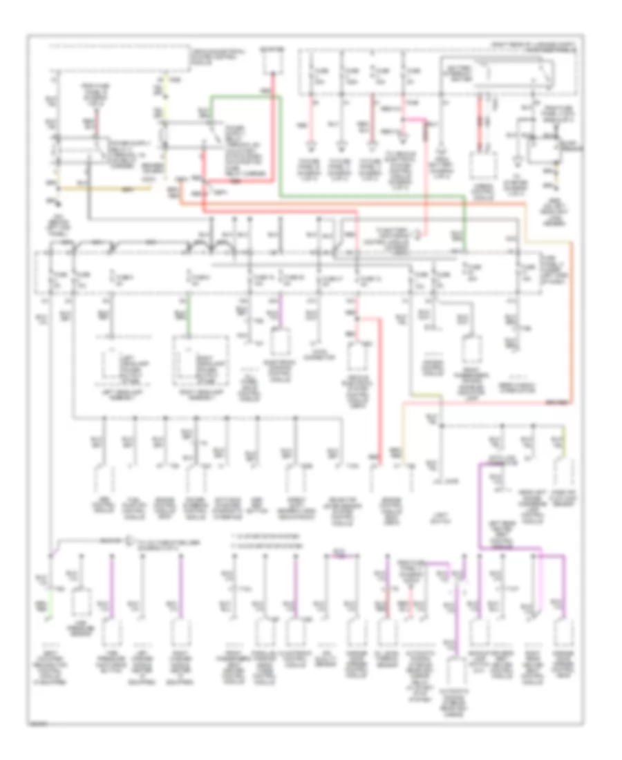
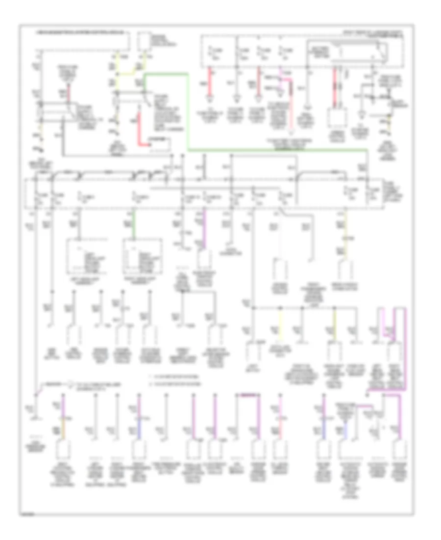
2.0L Turbo, Power Distribution Wiring Diagram (1 of 4) for Audi A3 2.0 TDI 2012
 https://portal-diagnostov.com/license.html
Automotive Electricians Portal FZCO
Automotive Electricians Portal FZCO
https://portal-diagnostov.com/license.html
https://portal-diagnostov.com/license.html
Automotive Electricians Portal FZCO
Automotive Electricians Portal FZCO
List of elements for 2.0L Turbo, Power Distribution Wiring Diagram (1 of 4) for Audi A3 2.0 TDI 2012:
- (right rear of luggage compt) main fuse panel d
- 18-pin connector
- 18a
- 19a
- 20a
- 40a
- 41a
- 47a
- Abs control module
- Air bag control module
- Air quality sensor
- Airbag control module
- All- wheel drive control module
- Asr/ esp button
- Automatic dimming interior rearview mirror
- Automatic dimming interior rearview mirror relay (w/ start/ stop system)
- Backup lamp switch (m/t)
- Battery interrupt ignitier
- Cbfa
- Ccta
- Climatronic control module
- Data bus on board diagnostic interface
- Data link connector
- Direct shift gearbox (dsg) mechatronic
- Driver's seat heater control module
- Electronic damping control module
- Engine control module (ecm)
- Engine control module (ecm) (cbfa)
- From battery (diagram 4 of 4)
- From fuse panel a (dia- gram 2 of 4)
- From fuse panel b (diagram 4 of 4)
- From fuse panel c (diagram 2 of 4)
- Front passenger's air bag disabled indicator lamp
- Front passenger's seat heater control module
- Fuel pump (fp) control module
- Fuse 10a
- Fuse 125a
- Fuse 15a
- Fuse 18 5a
- Fuse 19 10a
- Fuse 20 5a
- Fuse 30a
- Fuse 40a
- Fuse 47 5a
- Fuse 5 5a
- Fuse 5a
- Fuse 6 5a
- Fuse 80a
- Fuse panel c (under left side of dash)
- G44 (behind left kick panel)
- G655 (on left headlight long member)
- Garage door opener control head
- Garage door opener control module
- Headlight range/ cornering lamp control module
- High pressure sensor
- Left headlamp assembly
- Left headlamp power output stage
- Left rear heated seat control module
- Left washer nozzle heater (if equipped)
- Light switch
- Mass air flow (maf) sensor
- Nca
- Oil level thermal sensor
- Parallel parking assis- tance control module
- Power steering control module
- Rear window wiper motor
- Red
- Ressor
- Right headlamp assembly
- Right headlamp power output stage
- Right rear heated seat control module
- Right washer nozzle heater (if equipped)
- Seat occupied recognition control module (if equipped)
- Selector lever sensor system control module
- Starter
- Supp- +
- T10e
- T10k
- T10t
- T10u
- T16d
- T16f
- T20e
- T2aa
- T2ab
- T3w
- T52b
- T52c
- T5g
- T6q
- T8b
- T8y
- T94
- Tire pressure monitoring button
- To battery montoring control module (diagram 4 of 4)
- To fuse panel a (diagram 2 of 4)
- To fuse panel b (diagram 4 of 4)
- To fuse panel c (diagram 3 of 4)
- To starter (diagram 4 of 4)
- To vehicle electrical system control module (diagram 2 of 4)
- To voltage stabilizer (diagram 2 of 4)
- Vehicle electrical system control module
- Vehicle electrical system control module (cbfa)
- W/ start/stop system
- W/o start/stop system
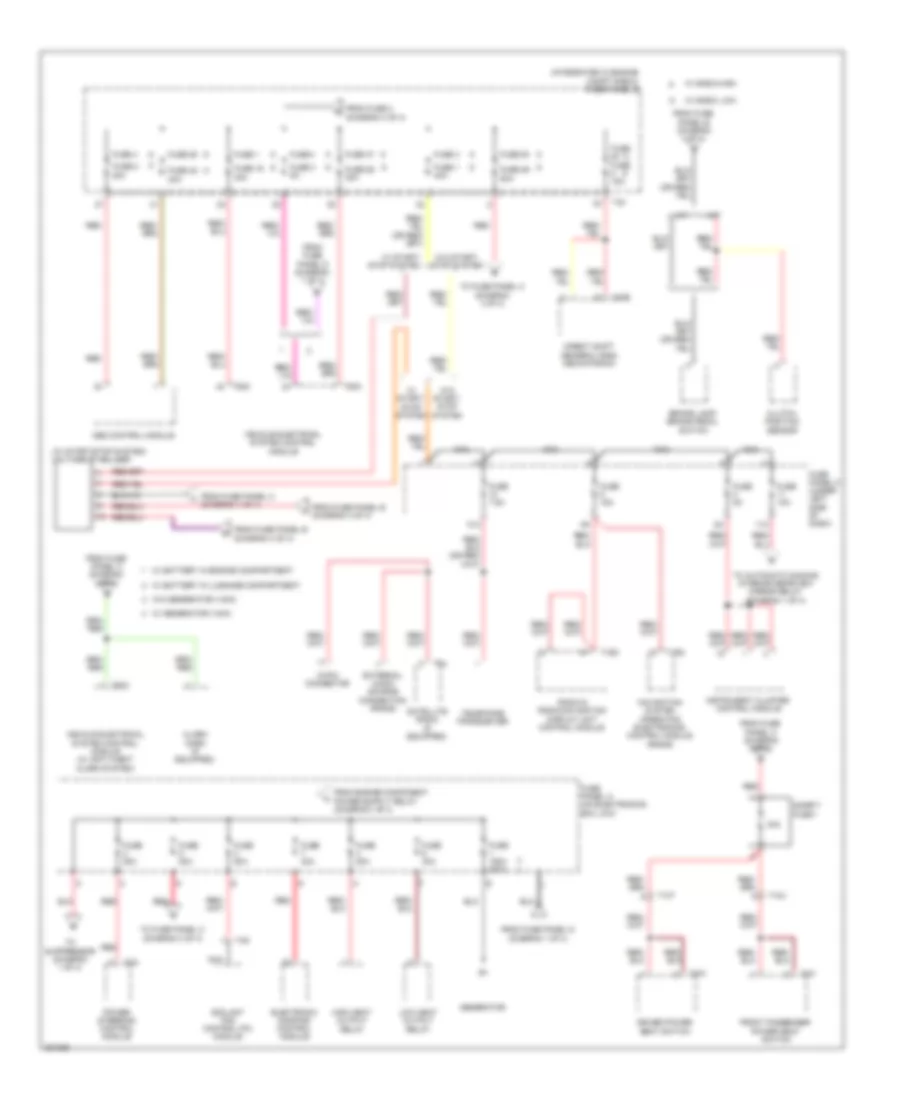
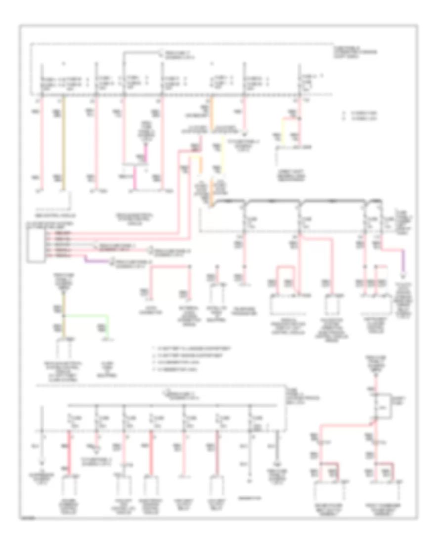
2.0L Turbo, Power Distribution Wiring Diagram (2 of 4) for Audi A3 2.0 TDI 2012
 https://portal-diagnostov.com/license.html
Automotive Electricians Portal FZCO
Automotive Electricians Portal FZCO
https://portal-diagnostov.com/license.html
https://portal-diagnostov.com/license.html
Automotive Electricians Portal FZCO
Automotive Electricians Portal FZCOList of elements for 2.0L Turbo, Power Distribution Wiring Diagram (2 of 4) for Audi A3 2.0 TDI 2012:
- (integrated in engine compt e-box) fuse panel b
- (w/ start/stop system) voltage stabilizer
- 10a
- 11a
- 18-pin connector
- 30a
- A/t
- Abs control module
- Alarm horn (if equipped)
- Brake lamp/ brake pedal switch
- Clutch position sensor
- Coolant fan control (fc) module
- Direct shift gearbox (dsg) mechatronic
- Driver power seat switch
- Electronic damping control module
- External audio source connection (rns-e)
- From fuse 2 (diagram 4 of 4)
- From fuse panel b (diagram 4 of 4)
- From fuse panel c (diagram 1 of 4)
- From fuse panel c (diagram 3 of 4)
- From fuse panel d (diagram 1 of 4)
- Front passenger power seat switch
- Fuse
- Fuse 1
- Fuse 1 40a
- Fuse 10a
- Fuse 150a 200a
- Fuse 15a
- Fuse 16 30a
- Fuse 2 30a
- Fuse 25
- Fuse 26 30a
- Fuse 29 50a
- Fuse 3
- Fuse 3 5a
- Fuse 30a
- Fuse 4
- Fuse 40a
- Fuse 47
- Fuse 48 40a
- Fuse 50a
- Fuse 53
- Fuse 5a
- Fuse 7.5a
- Fuse 80a
- Fuse panel a (on electronics box low)
- Fuse panel c (under left side of dash)
- Generator
- High heat output relay
- Instrument cluster control module
- Low heat output relay
- M/t
- Navigation system operatng electronics control module (rns-e)
- Nca
- Power steering control module
- Radio & radio/navigation display unit control module
- Red
- Safety fuse 1
- Satellite radio (if equipped)
- T10t
- T10u
- T16g
- T20e
- T2a
- T40
- T4d
- T4w
- T4x
- T52a
- T52c
- T8u
- Telephone transceiver
- To automatic dimming interior rearview mirror relay (diagram 1 of 4)
- To fuse panel c (diagram 3 of 4)
- To suppressor (diagram 1 of 4)
- Vehicle electrical system control module
- Vehicle electrical system control module (w/ anti-theft alarm system)
- W/ battery in engine compartment
- W/ battery in luggage compartment
- W/ e-box high
- W/ e-box low
- W/ generator (140a)
- W/ start/ stop system
- W/o generator (140a)
- W/o start/ stop system
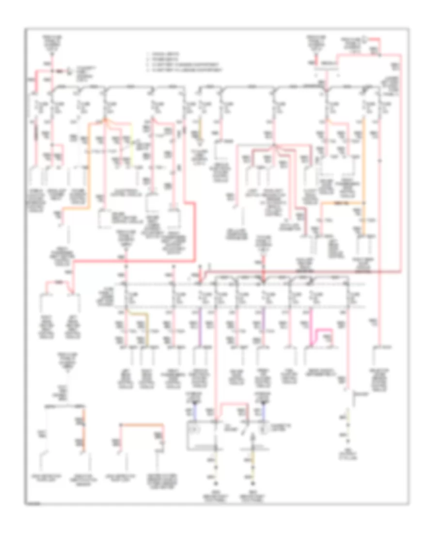
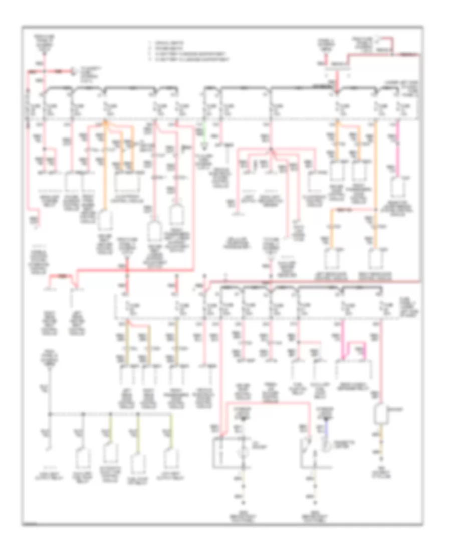
2.0L Turbo, Power Distribution Wiring Diagram (3 of 4) for Audi A3 2.0 TDI 2012
 https://portal-diagnostov.com/license.html
Automotive Electricians Portal FZCO
Automotive Electricians Portal FZCO
https://portal-diagnostov.com/license.html
https://portal-diagnostov.com/license.html
Automotive Electricians Portal FZCO
Automotive Electricians Portal FZCOList of elements for 2.0L Turbo, Power Distribution Wiring Diagram (3 of 4) for Audi A3 2.0 TDI 2012:
- (under left side of dash) fuse panel c
- 12a
- 12v socket
- 13a
- 14a
- 15a
- 16a
- 17a
- 22a
- 23a
- 24a
- 25a
- 26a
- 27a
- 28a
- 32a
- 33a
- 34a
- 36a
- 37a
- 38a
- 43a
- Auxiliary heater radio receiver
- Cbfa
- Ccta
- Cellular/ telephone tranceiver
- Cigarette lighter
- Climat- ronic control module
- Climatronic control module
- Data link connector
- Driver door control module
- Driver seat heater control module
- Driver seat lumbar support adjustment switch
- Fresh air blower control module
- From fuse panel a (diagram 2 of 4)
- From fuse panel b (diagram 2 of 4)
- From fuse panel b (diagram 4 of 4)
- From fuse panel c (diagram 3 of 4)
- From fuse u panel d (diagram 1 of 4)
- Front passenger seat heater control module
- Front passenger's door control module
- Front passenger's seat lumbar support adjustment switch
- Fuel pump (fp) control module
- Fuse 10a
- Fuse 15a
- Fuse 20a
- Fuse 30a
- Fuse 40a
- Fuse 5a
- Fuse panel c (under left side of dash)
- G62 (on right "c" pillar)
- G638 (behind right kick panel)
- Headlamp washer relay
- Heated oxygen sensor (ho2s) & oxygen sensor (o2s) heater
- Interior lights system
- Leak detection pump (ldp)
- Left rear door control module
- Left rear door module control
- Left rear heated seat control module
- Light switch
- Manual seats
- Models location system interface control module
- Nca
- Power seats
- Power sunroof control module
- Radiator identification sensor
- Rain/light recognition sensor (w/ automatic head & taillight control)
- Rear window defogger relay
- Red
- Right rear door control module
- Right rear door module control
- Right rear heated seat control module
- Selector lever sensor system control module
- Socket
- T10a
- T10k
- T10t
- T10u
- T16d
- T20
- T20a
- T20f
- T20g
- T20l
- T20m
- T20n
- T20o
- T2bw
- T52b
- T6b
- T8n
- T8o
- To alarm horn (diagram 2 of 4)
- To fuse panel c (diagram 3 of 4)
- To safety fuse 1 (diagram 2 of 4)
- Vehicle electrical system control module
- W/ battery in engine compartment
- W/ battery in luggage compartment
- W/ heated seats
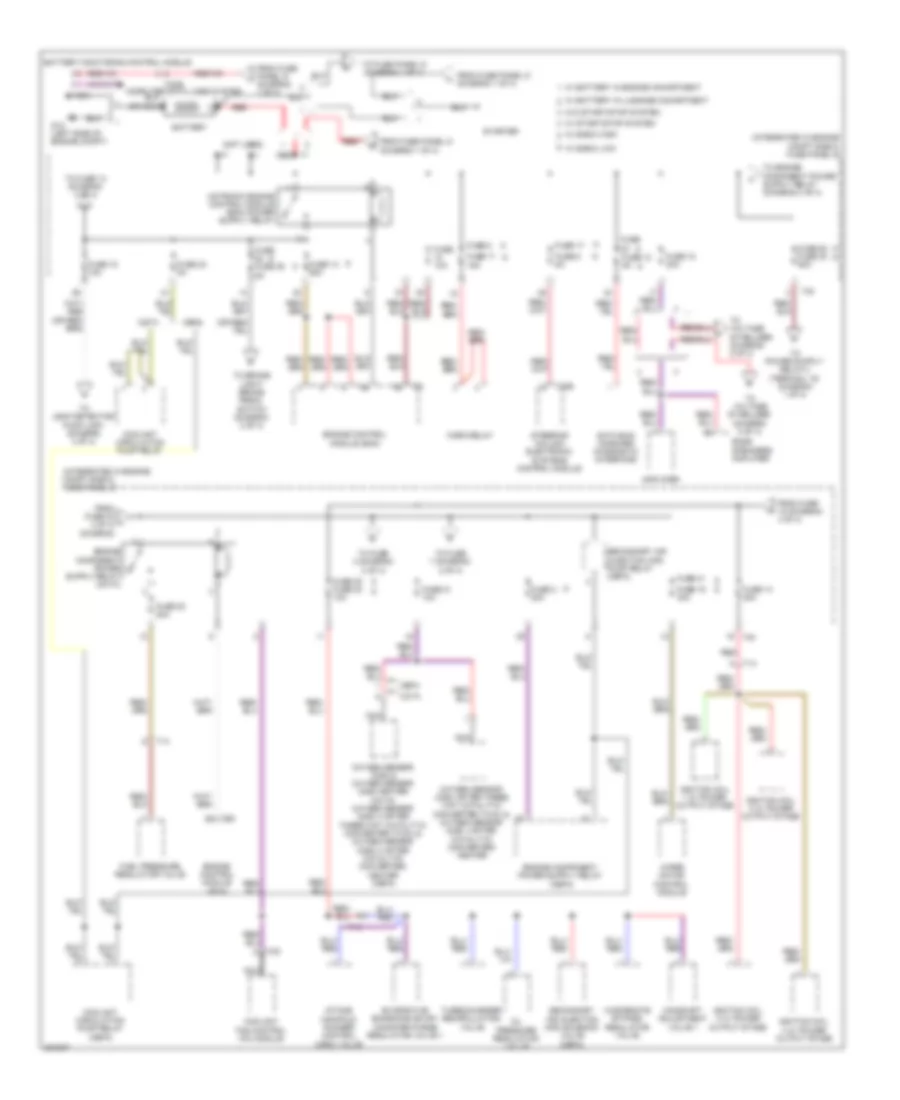
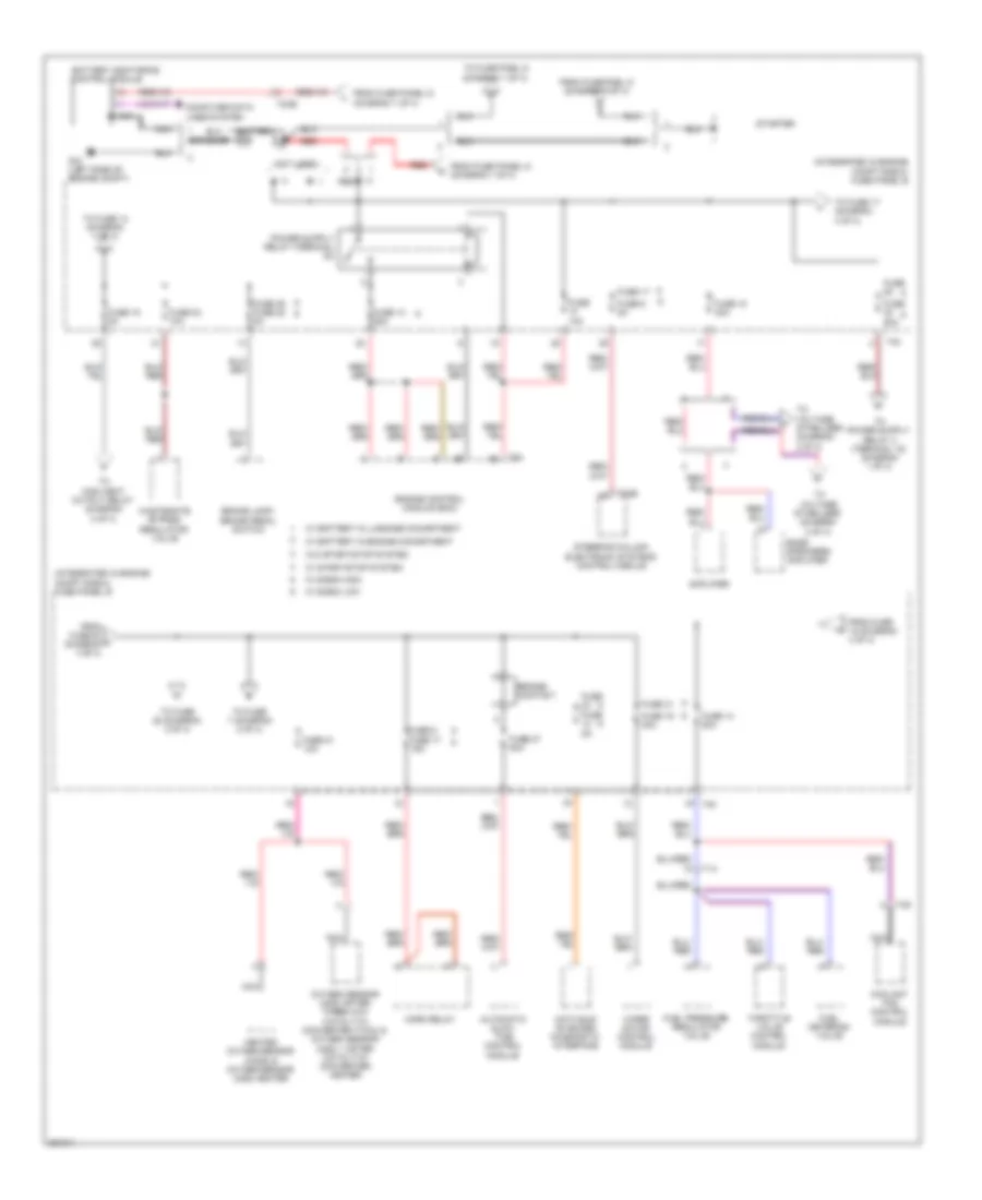
2.0L Turbo, Power Distribution Wiring Diagram (4 of 4) for Audi A3 2.0 TDI 2012
 https://portal-diagnostov.com/license.html
Automotive Electricians Portal FZCO
Automotive Electricians Portal FZCO
https://portal-diagnostov.com/license.html
https://portal-diagnostov.com/license.html
Automotive Electricians Portal FZCO
Automotive Electricians Portal FZCOList of elements for 2.0L Turbo, Power Distribution Wiring Diagram (4 of 4) for Audi A3 2.0 TDI 2012:
- (integrated in engine compt e-box) fuse panel b
- (not used)
- Amplifier
- Bass speakers amplifier
- Battery
- Battery monitoring control module
- Camshaft adjustment valve 1
- Cbfa
- Ccta
- Computer data lines system
- Coolant circulation pump relay
- Coolant circulation pump relay (cbfa)
- Coolant fan control (fc) module
- Data bus on board diagnostic interface
- Engine control module (ecm)
- Evaprative emissions (evap) canister purge regulator valve 1
- From fuse 15 (diagram 4 of 4)
- From fuse 30 l 4 of 4) (diagram
- From fuse panel d (diagram 1 of 4)
- Fuel pressure regulator valve
- Fuse
- Fuse 10a
- Fuse 12 5a
- Fuse 13 25a
- Fuse 14 20a
- Fuse 15 10a
- Fuse 17
- Fuse 17 15a
- Fuse 18 30a
- Fuse 19 30a
- Fuse 2 20a
- Fuse 20 20a
- Fuse 21 10a
- Fuse 23 5a
- Fuse 31
- Fuse 38 fuse 24 10a
- Fuse 5
- Fuse 52 fuse 30 50a
- Fuse 6 5a
- Fuse fuse 39 5a
- G12 (left side of engine compt)
- Horn relay
- Ignition coil 1 w/ power output stage
- Ignition coil 2 w/ power output stage
- Ignition coil 3 w/ power output stage
- Ignition coil 4 w/ power output stage
- Intake manifold runner control (imrc) valve
- Nca
- Oil pressure regulation valve
- Oxygen sensor (o2s) & oxygen sensor (o2s) heater (ccta) oxygen sensor (o2s) 3 (after three way catalytic converter (twc)) & oxygen sensor (o2s) 3 (after catalytic converter) heater (cbfa)
- Oxygen sensor (o2s) (after three way catalytic converter (twc)) & oxygen sensor (o2s) 1(after catalytic converter) heater
- Red
- Secondary air injection (air) pump relay (cbfa)
- Secondary air injection (air) solenoid valve (cbfa)
- Starter
- Steering column electronic systems control module
- T14
- T20b
- T2ce
- T40
- T4d
- T94
- To brake light/ brake pedal switch (diagram 2 of 4)
- To fuse 14 (diagram 4 of 4)
- To fuse 3 (diagram 2 of 4)
- To fuse 7 (diagram 2 of 4)
- To fuse panel d (diagram 1 of 4)
- To leak detection pump (ldp) (diagram 3 of 4)
- To voltage stabilizer (diagram 2 of 4)
- Turbocharger recirculating valve
- W/ battery in engine comartment
- W/ battery in luggage comartment
- W/ e-box high
- W/ e-box low
- W/ start/stop system
- W/o start/stop system
- Wastegate bypass regulator valve
- Wiper motor control module
2.0L TURBO DIESEL
2.0L Turbo Diesel, Power Distribution Wiring Diagram (1 of 4) for Audi A3 2.0 TDI 2012
 https://portal-diagnostov.com/license.html
Automotive Electricians Portal FZCO
Automotive Electricians Portal FZCO
https://portal-diagnostov.com/license.html
https://portal-diagnostov.com/license.html
Automotive Electricians Portal FZCO
Automotive Electricians Portal FZCOList of elements for 2.0L Turbo Diesel, Power Distribution Wiring Diagram (1 of 4) for Audi A3 2.0 TDI 2012:
- (right rear of luggage compt) main fuse panel d
- 18-pin connector
- 19a
- 20a
- 40a
- 41a
- 47a
- Abs control module
- Air bag control module
- Air quality sensor
- Airbag control module
- All- wheel drive control module
- Asr/ esp button
- Automatic dimming interior mirror
- Automatic dimming interior rearview mirror relay (w/ start/ stop system)
- Battery interrupt ignitier
- Climatronic control module
- Data bus on board diagnostic interface
- Data link connector (dlc)
- Direct shift gearbox (dsg) mechatronic
- Driver seat heater control module
- Electronic damping control module
- Engine control module (ecm)
- From battery (diagram 4 of 4)
- From fuse panel a (dia- gram 2 of 4)
- From fuse panel b (diagram 4 of 4)
- From fuse panel c (diagram 2 of 4)
- Front passenger's air bag disabled indicator lamp
- Front passenger's seat heater module
- Fuse 10a
- Fuse 125a
- Fuse 15a
- Fuse 19 10a
- Fuse 20 5a
- Fuse 30a
- Fuse 40a
- Fuse 5 5a
- Fuse 5a
- Fuse 6 5a
- Fuse 80a
- Fuse panel c (under left side of dash)
- G44 (behind left kick panel)
- G655 (on left headlight long member)
- Garage door opener control head
- Garage door opener control module
- Headlight range/ cornering lamp control module
- High pressure sensor
- Left headlamp assembly
- Left headlamp power output stage
- Left rear heated seat control module
- Left washer nozzle heater (if equipped)
- Light switch
- Mass air flow (maf) sensor
- Nca
- Oil level thermal sensor
- Parallel parking assistance control module
- Positive crankcase ventilation (pcv) heating element (if equipped)
- Power steering control module
- Rear window wiper motor
- Red
- Ressor
- Right headlamp assembly
- Right headlamp power output stage
- Right rear heated seat control module
- Right washer nozzle heater (if equipped)
- Seat occupied recognition control module (if equipped)
- Selector lever sensor system control module
- Starter
- Supp- +
- T10e
- T10k
- T10t
- T10u
- T16d
- T16f
- T20e
- T2aa
- T2ab
- T3w
- T52b
- T5g
- T6q
- T8b
- T8y
- T94
- Tire pressure monitoring button
- To battery monitoring control module (diagram 4 of 4)
- To fuse panel a (diagram 2 of 4)
- To fuse panel b (diagram 4 of 4)
- To fuse panel c (diagram 3 of 4)
- To starter (diagram 4 of 4)
- To vehicle electrical system control module (diagram 2 of 4)
- To voltage stabilizer (diagram 2 of 4)
- Vehicle electrical system control module
- W/ start/stop system
- W/o start/stop system
2.0L Turbo Diesel, Power Distribution Wiring Diagram (2 of 4) for Audi A3 2.0 TDI 2012
 https://portal-diagnostov.com/license.html
Automotive Electricians Portal FZCO
Automotive Electricians Portal FZCO
https://portal-diagnostov.com/license.html
https://portal-diagnostov.com/license.html
Automotive Electricians Portal FZCO
Automotive Electricians Portal FZCOList of elements for 2.0L Turbo Diesel, Power Distribution Wiring Diagram (2 of 4) for Audi A3 2.0 TDI 2012:
- (w/ start/stop/ system) voltage stabilizer
- 10a
- 11a
- 18-pin connector
- 30a
- Abs control module
- Alarm horn (if equipped)
- Coolant fan control (fc) module
- Direct shift gearbox (dsg) mechatronic
- Driver power seat switch assembly
- Electronic damping control module
- External audio source connection (rns-e)
- From fuse 17 (diagram 4 of 4)
- From fuse panel b (diagram 4 of 4)
- From fuse panel c (diagram 1 of 4)
- From fuse panel c (diagram 3 of 4)
- From fuse panel d (diagram 1 of 4)
- Front passenger power seat assembly
- Fuse 1
- Fuse 1 40a
- Fuse 10a
- Fuse 13
- Fuse 150a 200a
- Fuse 15a
- Fuse 16 30a
- Fuse 2 20a
- Fuse 25
- Fuse 26 30a
- Fuse 28 40a
- Fuse 29 50a
- Fuse 3
- Fuse 30a
- Fuse 4
- Fuse 40a
- Fuse 47
- Fuse 48 40a
- Fuse 50a
- Fuse 53
- Fuse 5a
- Fuse 7.5a
- Fuse 80a
- Fuse panel a (on electronics box low)
- Fuse panel b (integrated in engine compt e-box)
- Fuse panel c (under left side of dash)
- Generator
- High heat output relay
- Instrument cluster control module
- Low heat output relay
- Navigation system operating electronics control module (rns-e)
- Nca
- Power steering control module
- Radio & radio/navigation display unit control module
- Red
- Safety fuse 1
- Satellite radio (if equipped)
- T16g
- T20e
- T2a
- T40
- T4d
- T4w
- T4x
- T52a
- T52c
- T8u
- Telephone transceiver
- To auto- matic dimming interior rearview mirror relay diagram (1 of 4)
- To fuse panel c (diagram 3 of 4)
- To suppressor (diagram 1 of 4)
- Vehicle electrical system control module
- Vehicle electrical system control module (w/ anti-theft alarm system)
- W/ battery engine compartment
- W/ battery in luggage compartment
- W/ e-box high
- W/ e-box low
- W/ generator (140a)
- W/ start/ stop system
- W/o generator (140a)
- W/o start/ stop system
2.0L Turbo Diesel, Power Distribution Wiring Diagram (3 of 4) for Audi A3 2.0 TDI 2012
 https://portal-diagnostov.com/license.html
Automotive Electricians Portal FZCO
Automotive Electricians Portal FZCO
https://portal-diagnostov.com/license.html
https://portal-diagnostov.com/license.html
Automotive Electricians Portal FZCO
Automotive Electricians Portal FZCOList of elements for 2.0L Turbo Diesel, Power Distribution Wiring Diagram (3 of 4) for Audi A3 2.0 TDI 2012:
- (under left side of dash) fuse panel c
- 12a
- 12v socket
- 13a
- 14a
- 15a
- 16a
- 17a
- 22a
- 23a
- 24a
- 25a
- 26a
- 27a
- 28a
- 32a
- 33a
- 34a
- 36a
- 37a
- 38a
- 39a
- 43a
- Automatic glow time control module
- Auxiliary fuel pump relay
- Auxiliary heater radio receiver
- Auxillary fuel pump relay
- Cellular telephone transcever 1
- Cigarette lighter
- Climatronic control module
- Data link conne- ctor
- Driver door control module
- Driver seat heater control module
- Driver seat lumbar support adjustment switch
- Fresh air blower control module
- From fuse panel a (diagram 2 of 4)
- From fuse panel b (diagram 2 of 4)
- From fuse panel d (diagram 1 of 4)
- From panel b (diagram 4 of 4)
- Front pass- enger seat heater control module
- Front passenger's door control module
- Front passenger's seat lumbar support adjustment switch
- Fuel pump (fp) relay
- Fuse 10a
- Fuse 15a
- Fuse 20a
- Fuse 30a
- Fuse 40a
- Fuse 5a
- Fuse panel c (under left side of dash)
- G62 (on right "c" pillar)
- G638 (behind right kick panel)
- Headlamp washer relay
- High heat output relay
- Interior lights system
- Left rear door control module
- Left rear heated seat control module
- Light switch
- Low heat output relay
- Manual seats
- Models location system interface control module
- Nca
- Panel c (diagram 3 of 4)
- Power seats
- Power sunroof control module
- Rain/light recognition sensor
- Rear window defogger relay
- Red
- Right rear door control module
- Right rear heated seat control module
- Seats
- Selector lever sensor system control module
- Socket
- T10k
- T10t
- T10u
- T16d
- T20
- T20a
- T20f
- T20g
- T20i
- T20l
- T20m
- T20n
- T20o
- T2bw
- T52b
- T6b
- T8n
- T8o
- To alarm horn (diagram 2 of 4)
- To fuse panel c (diagram 3 of 4)
- To safety fuse 1 (diagram 2 of 4)
- Vehicle electrical system control module
- W/ battery in engine compartment
- W/ battery in luggage compartment
- W/ heated
2.0L Turbo Diesel, Power Distribution Wiring Diagram (4 of 4) for Audi A3 2.0 TDI 2012
 https://portal-diagnostov.com/license.html
Automotive Electricians Portal FZCO
Automotive Electricians Portal FZCO
https://portal-diagnostov.com/license.html
https://portal-diagnostov.com/license.html
Automotive Electricians Portal FZCO
Automotive Electricians Portal FZCOList of elements for 2.0L Turbo Diesel, Power Distribution Wiring Diagram (4 of 4) for Audi A3 2.0 TDI 2012:
- (integrated in engine compt e-box) fuse panel b
- (not used)
- Amplifier
- Automatic glow time control module
- Bass speakers amplifier
- Battery
- Battery monitoring control module
- Brake lamp/ brake pedal switch
- Bridge contact
- Computer data lines system
- Coolant fan control module
- Data bus on board diagnostic interface
- Engine control module (ecm)
- From fuse 15 (diagram 4 of 4)
- From fuse 30 l (diagram 4 of 4)
- From fuse panel d (diagram 1 of 4)
- From fuse pnel d (diagram 1 of 4)
- Fuel metering valve
- Fuel pressure regulator valve
- Fuse
- Fuse 10a
- Fuse 13 25a
- Fuse 14 20a
- Fuse 15 5a
- Fuse 17
- Fuse 18 30a
- Fuse 19 30a
- Fuse 21 10a
- Fuse 23 10a
- Fuse 27 50a
- Fuse 31
- Fuse 39 fuse 22 5a
- Fuse 5 fuse 17 15a
- Fuse 50a
- Fuse 5a
- Fuse 6 5a
- G12 (left side of engine compt)
- Heated oxygen sensor (ho2s) & oxygen sensor (o2s) heater
- Horn relay
- Nca
- Oxygen sensor (o2s) (after three way catalytic converter (twc)) & oxygen sensor (o2s) 1 (after catalytic converter) heater
- Red
- Starter
- Steering column electronic systems control module
- T14
- T20b
- T2ce
- T40
- T4d
- T94
- Throttle valve control module
- To fuse 14 (diagram 4 of 4)
- To fuse 17 (diagram 4 of 4)
- To fuse 28 (diagram 2 of 4)
- To fuse 7 (diagram 2 of 4)
- To fuse pnel d (diagram 1 of 4)
- To high heat output relay (diagram 3 of 4)
- To voltage stabilizer (diagram 2 of 4)
- Voltage stabilizer (diagram 2 of 4)
- W/ battery in engine comartment
- W/ battery in luggage comartment
- W/ e-box high
- W/ e-box low
- W/ start/stop system
- W/o start/stop system
- Wastegate bypass regulator valve
- Wiper motor control module

 Čeština
 Dansk
Dansk Deutsch
 Ελληνικά
 English
 English
 Español
 Suomi
Suomi Français
 Français
 עברית
עברית Hrvatski
 Magyar
 Italiano
 日本語
日本語 한국어
한국어 Nederlands
 Polski
 Português
 Português
 Română
 Русский
 Slovenčina
 Slovenščina
 Svenska
 Türkçe
