Čeština
 Dansk
Dansk Deutsch
 Ελληνικά
 English
 English
 Español
 Suomi
Suomi Français
 Français
 עברית
עברית Hrvatski
 Magyar
 Italiano
 日本語
日本語 한국어
한국어 Nederlands
 Polski
 Português
 Português
 Română
 Русский
 Slovenčina
 Slovenščina
 Svenska
 Türkçe

SHIFT INTERLOCK
Electromechanical Parking Brake Wiring Diagram for Audi A7 Prestige 2013


List of elements for Electromechanical Parking Brake Wiring Diagram for Audi A7 Prestige 2013:
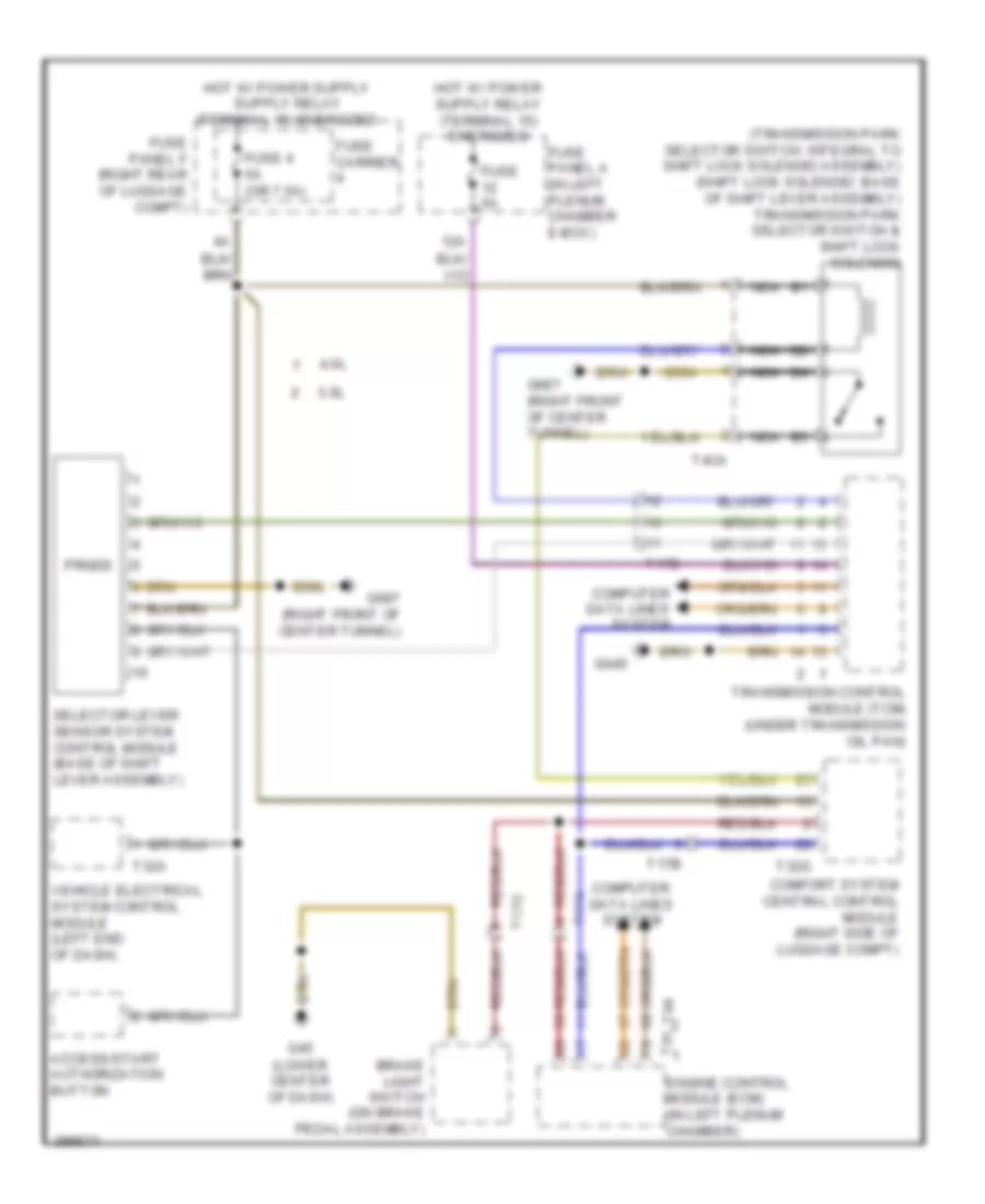
Shift Interlock Wiring Diagram for Audi A7 Prestige 2013
List of elements for Shift Interlock Wiring Diagram for Audi A7 Prestige 2013:
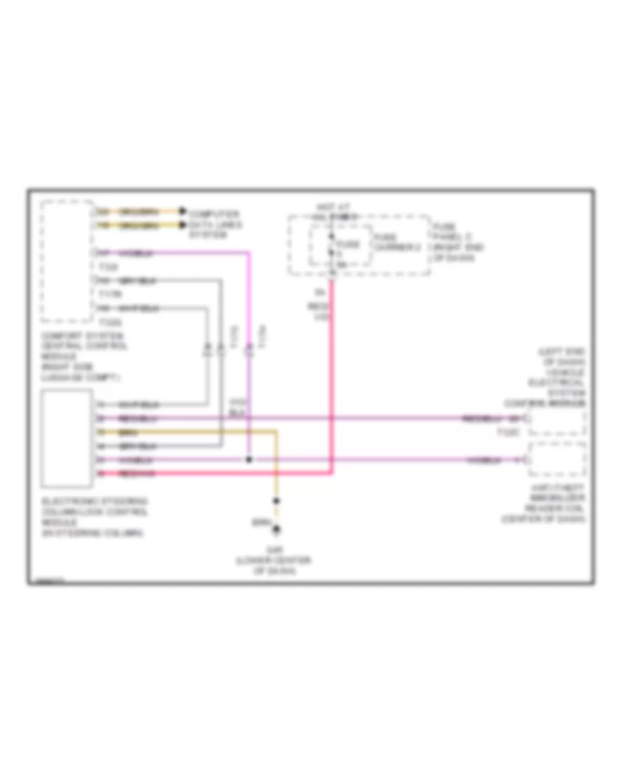
Steering Column Wiring Diagram for Audi A7 Prestige 2013
List of elements for Steering Column Wiring Diagram for Audi A7 Prestige 2013: