ELECTRONIC POWER STEERING
Electronic Power Steering Wiring Diagram, with Active Brake for Cadillac STS V 2008
 https://portal-diagnostov.com/license.html
Automotive Electricians Portal FZCO
Automotive Electricians Portal FZCO
https://portal-diagnostov.com/license.html
https://portal-diagnostov.com/license.html
Automotive Electricians Portal FZCO
Automotive Electricians Portal FZCO
List of elements for Electronic Power Steering Wiring Diagram, with Active Brake for Cadillac STS V 2008:
- (near left front strut tower, at bottom of inside fender well) g101
- Actr frt active sig gnd
- Actr frt active sig mtr u
- Actr frt active sig mtr w
- Actr frt active sig u
- Actr frt active sig v
- Actr frt active sig w
- Afs fuse 30a
- Batt positive volt
- Can bus high serial data
- Can bus low serial data
- Computer data lines system
- Electronic brake control module (ebcm) (on right front corner of engine compt, behind right front wheel)
- G200 (in passenger compt, behind left kick panel)
- Gnd
- Hot at all times
- Hot w/ run relay energized
- Ign 3 fuse 10a
- J/c
- Left rear fuse block (under left side of rear seat)
- Power steering control module (pscm) (left side of dash, above park brake pedal)
- Serial data +
- Serial data -
- Serial data wakeup
- Steering angle sensor (on base of steering column)
- Tan
- Tan/
- Underhood fuse block (right front side of engine compt)
- Upper intermediate steering shaft
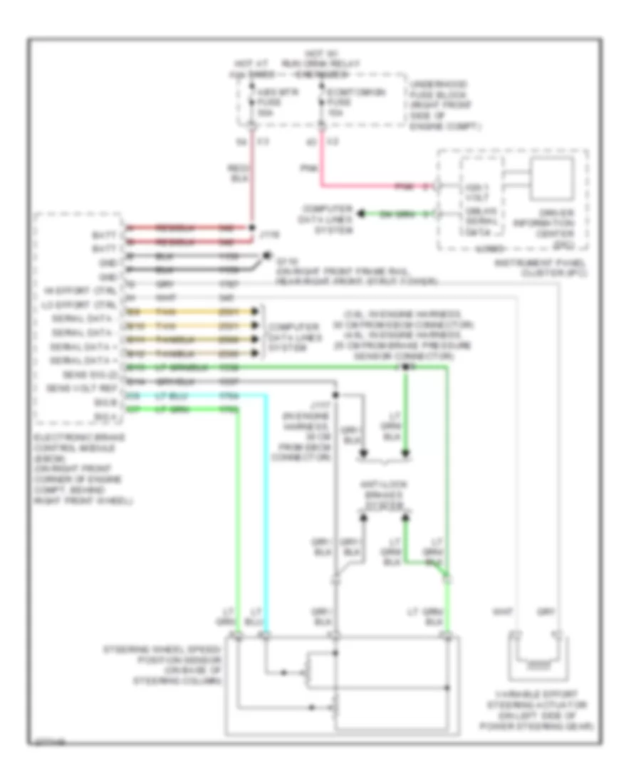
Electronic Power Steering Wiring Diagram, without Active Brake for Cadillac STS V 2008
 https://portal-diagnostov.com/license.html
Automotive Electricians Portal FZCO
Automotive Electricians Portal FZCO
https://portal-diagnostov.com/license.html
https://portal-diagnostov.com/license.html
Automotive Electricians Portal FZCO
Automotive Electricians Portal FZCOList of elements for Electronic Power Steering Wiring Diagram, without Active Brake for Cadillac STS V 2008:
- (3.6l: in engine harness, 30 cm from ebcm connector) (4.6l: in engine harness, 25 cm from brake pressure sensor connector) j118
- Abs mtr fuse 50a
- Anti-lock brakes system
- B10
- B11
- B12
- B13
- B14
- Batt
- Computer data lines system
- Driver information center (dic)
- Ecm/tcm/ign fuse 15a
- Electronic brake control module (ebcm) (on right front corner of engine compt, behind right front wheel)
- G110 (on right front frame rail, near right front strut tower)
- Gmlan serial data
- Gnd
- Hi effort ctrl
- Hot at all times
- Hot w/ run crnk relay energized
- Ign 1 volt
- Instrument panel cluster (ipc)
- J117 (in engine harness, 36 cm from ebcm connector)
- J119
- Lo effort ctrl
- Logic
- Pnk
- Sens sig (2)
- Sens volt ref
- Serial data +
- Serial data -
- Sig a
- Sig b
- Steering wheel speed/ position sensor (on base of steering column)
- Tan
- Underhood fuse block (right front side of engine compt)
- Variable effort steering actuator (on left side of power steering gear)

 Čeština
 Dansk
Dansk Deutsch
 Ελληνικά
 English
 English
 Español
 Suomi
Suomi Français
 Français
 עברית
עברית Hrvatski
 Magyar
 Italiano
 日本語
日本語 한국어
한국어 Nederlands
 Polski
 Português
 Português
 Română
 Русский
 Slovenčina
 Slovenščina
 Svenska
 Türkçe
