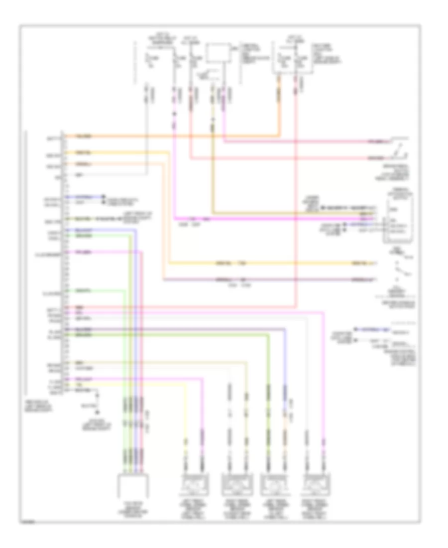
ANTI-LOCK BRAKES
Anti-lock Brakes Wiring Diagram for Land Rover Discovery 2 HSE 2012
 https://portal-diagnostov.com/license.html
Automotive Electricians Portal FZCO
Automotive Electricians Portal FZCO
https://portal-diagnostov.com/license.html
https://portal-diagnostov.com/license.html
Automotive Electricians Portal FZCO
Automotive Electricians Portal FZCO
List of elements for Anti-lock Brakes Wiring Diagram for Land Rover Discovery 2 HSE 2012:
- (left front of engine compt) g1d130c
- (under driver's seat) g3d135
- Abs module (left rear of engine compt)
- Batt p
- Batt v
- Battery junction box (left side of engine compt)
- Brake pedal switch (top of brake pedal assembly)
- C12g
- C12g c12h
- C12h
- C1bb01a
- C1bp02a
- C1bp02b
- C1bp02c
- C1e109b
- C23f c23e
- Can2 h
- Can2 l
- Cem
- Center console switch pack
- Central junction box (behind glove compt)
- Clus gnd
- Clus sensep
- Computer data lines system
- Dsc sw
- Dsc switch
- Engine control module (ecm) (top center of firewall)
- Fl gnd
- Fl sig
- Fr gnd
- Fr sig
- Fuse 30a
- Fuse 40a
- Fuse 5a
- G1d130c (left front of engine compt)
- Gnd
- Gnd p
- Gnd vps
- Hdc sw
- Hill descent switch
- Hot at all times
- Hot w/ ignition relay energized
- Hs can h
- Hs can l
- Ign
- Illum fet
- Left front wheel speed sensor (left front wheelwell)
- Left rear wheel speed sensor (in left wheelwell)
- Nca
- Red
- Right front wheel speed sensor (right front wheelwell)
- Right rear wheel speed sensor (in right rear wheelwell)
- Rl gnd
- Rl sig
- Rr gnd
- Rr sig
- Terrain optimization switch
- Yaw rate sensor (under center console)
 Čeština
 Dansk
Dansk Deutsch
 Ελληνικά
 English
 English
 Español
 Suomi
Suomi Français
 Français
 עברית
עברית Hrvatski
 Magyar
 Italiano
 日本語
日本語 한국어
한국어 Nederlands
 Polski
 Português
 Português
 Română
 Русский
 Slovenčina
 Slovenščina
 Svenska
 Türkçe
 中文 (中国)
