POWER DISTRIBUTION
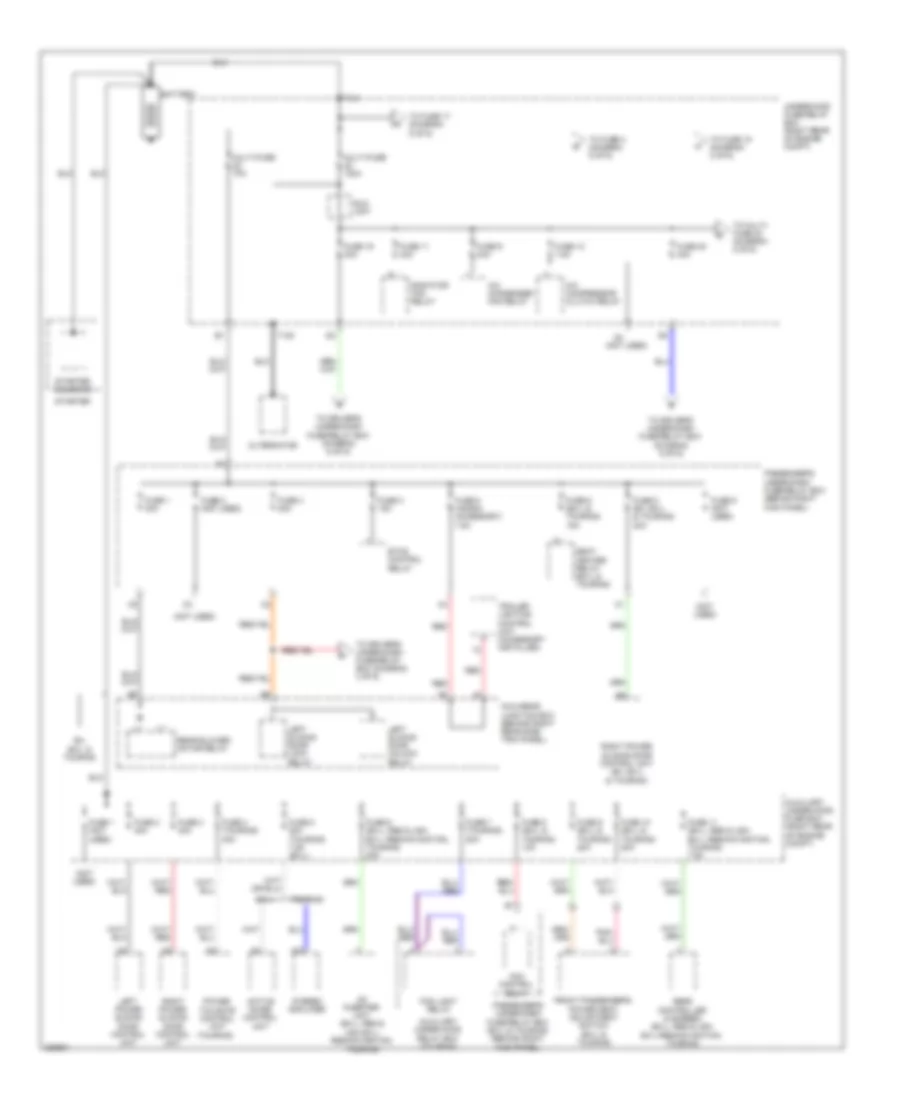
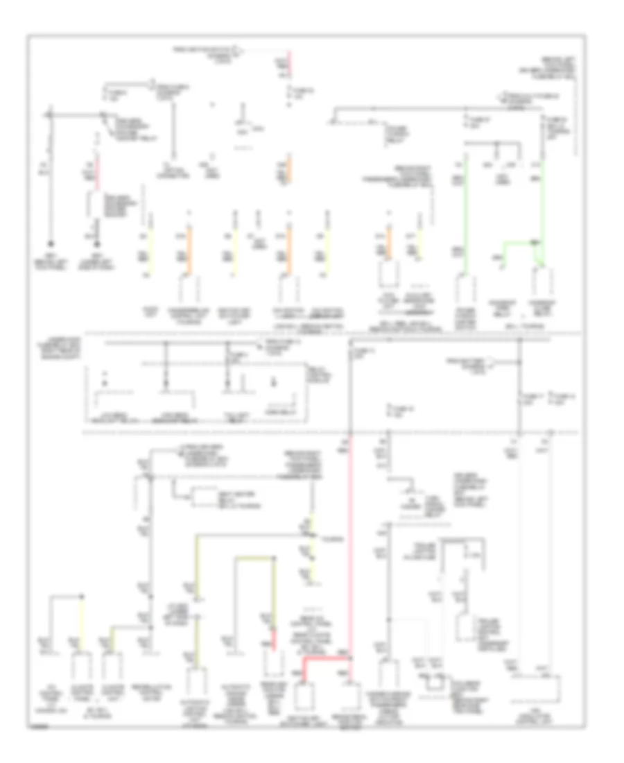
Power Distribution Wiring Diagram (1 of 6) for Honda Odyssey EX 2008
 https://portal-diagnostov.com/license.html
Automotive Electricians Portal FZCO
Automotive Electricians Portal FZCO
https://portal-diagnostov.com/license.html
https://portal-diagnostov.com/license.html
Automotive Electricians Portal FZCO
Automotive Electricians Portal FZCO
List of elements for Power Distribution Wiring Diagram (1 of 6) for Honda Odyssey EX 2008:
- (not used)
- (touring)
- A/c compressor clutch relay
- A/c condenser fan relay
- A10
- Ac inverter unit (ex-l, res & usa ex-l: res/navigation, touring)
- Acm control relay
- Active noise control unit
- Alternator
- Auxiliary under-hood fuse box (right rear of engine compt)
- Auxiliary under-hood relay box (touring)
- Battery
- Eld unit
- Etcs control relay
- Ex,
- Ex-l
- Ex-l & touring
- Fog light relay
- Front passenger's power seat adjustment switch (ex-l & touring)
- Fuse 1 (not used)
- Fuse 1 30a
- Fuse 10 (ex-l & touring) 20a
- Fuse 11 (ex-l, res & usa ex-l: res/navigation, touring) 7.5a
- Fuse 11 30a
- Fuse 12 7.5a
- Fuse 19 30a
- Fuse 2 (not used)
- Fuse 2 40a
- Fuse 20 40a
- Fuse 3 15a
- Fuse 3 40a
- Fuse 4 (touring) 40a
- Fuse 4 20a
- Fuse 5 (honda accessory) 7.5a
- Fuse 5 20a (touring) 7.5a (ex-l)
- Fuse 6 (ex-l & touring) 15a
- Fuse 6 (ex-l, res & usa ex-l: res/navigation, touring) 20a
- Fuse 7 (touring) 20a
- Fuse 8 (ex, ex-l & touring) 20a
- Fuse 8 (ex-l & touring) 10a
- Fuse 9 (ex-l & touring) 20a
- Fuse 9 (not used)
- Fuse 9 30a
- Left power sliding door control unit
- Left sliding door lock relay
- Left sliding door unlock relay
- Micu-rear junction box (behind right rear side trim panel)
- Multi-fuse 120a
- Multi-fuse 70a
- Passenger's under-dash fuse/relay box (behind right kick panel)
- Passenger's under-dash fuse/relay box (ex-l & touring) (behind right kick panel)
- Power tailgate control unit
- Radiator fan relay
- Rear blower motor relay
- Rear controller & screen (ex-l, res & usa ex-l:res/navigation, touring)
- Red
- Right power sliding door control unit
- Right power sliding door control unit (ex, ex-l & touring)
- Seat heater relay (ex-l & touring)
- Starter
- Starter solenoid
- Stereo amplifier
- T101
- T102
- To driver's under-dash fuse/relay box (diagram 3 of 6)
- To driver's under-dash fuse/relay box (diagram 6 of 6)
- To fuse 15 (diagram 2 of 6)
- To fuse 17 (diagram 5 of 6)
- To fuse 4 (diagram 5 of 6)
- To multi- fuse 23 (diagram 2 of 6)
- Touring
- Trailer lighting control unit (accessory installed)
- Under-hood fuse/relay box (right rear of engine compt)
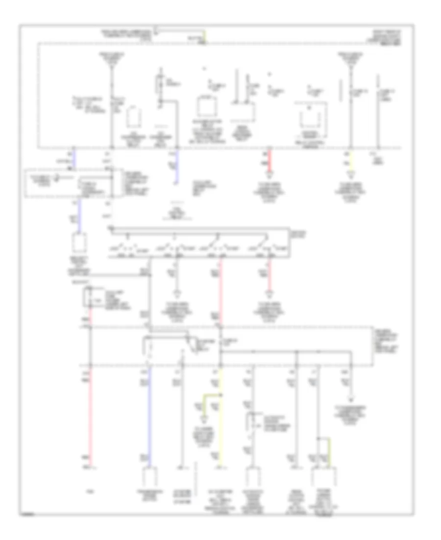
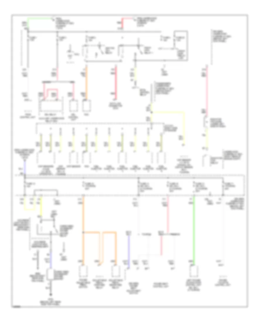
Power Distribution Wiring Diagram (2 of 6) for Honda Odyssey EX 2008
 https://portal-diagnostov.com/license.html
Automotive Electricians Portal FZCO
Automotive Electricians Portal FZCO
https://portal-diagnostov.com/license.html
https://portal-diagnostov.com/license.html
Automotive Electricians Portal FZCO
Automotive Electricians Portal FZCOList of elements for Power Distribution Wiring Diagram (2 of 6) for Honda Odyssey EX 2008:
- (diagram 3 of 6)
- (lx) (ex, ex-l & touring)
- (not used)
- (right rear of engine compt) under-hood fuse/ relay box
- 7.5a
- A/c compressor clutch relay
- A/c condenser fan relay
- A/c diode a
- A31
- Ac inverter unit (ex-l, res & usa ex-l: res/navigation, touring)
- Acc
- Automatic dimming inside mirror (accessory installed)
- Automatic dimming inside mirror in-line fuse
- Auxiliary fuse holder (under left side of dash)
- Auxiliary under-hood relay box
- Blower motor relay (lx, canada: dx) front blower motor relay (ex, ex-l & touring)
- Control block
- D15
- Driver's under-dash fuse/relay box (behind left kick panel)
- F13
- F19
- Fan control relay
- From driver's under-dash m fuse/relay box (diagram 2 of 6)
- From fuse 20 (diagram 1 of 6)
- Fuse 10 (not used)
- Fuse 15 40a
- Fuse 21 40a
- Fuse 30 10a
- Fuse 30a
- Fuse 33 (honda accessory) 7.5a
- Fuse 7 7.5a
- Fuse 8 15a
- Ignition switch
- Lock
- Multi- fuse 50a
- Multi-fuse 23 40a 50a
- N20
- Pcm
- Power mirror switch (usa: lx) (canada: lx, dx ex, ex-l & touring)
- Rear climate control unit (ex, ex-l & touring)
- Rear window defogger relay
- Red
- Relay control module
- Security control unit (accessory installed)
- Start
- Starter
- Starter cut relay
- Starter solenoid
- To driver's under-dash fuse/relay box
- To driver's under-dash fuse/relay box (diagram 4 of 6)
- To driver's under-dash fuse/relay box (diagram 5 of 6)
- To driver's under-dash fuse/relay box (diagram 6 of 6)
- To fuse 27 (diagram 5 of 6)
- To passenger's under-dash fuse/relay box (diagram 5 of 6)
- To under- hood fuse/ relay box (diagram 2 of 6)
- Transmission range switch
- X11
- X33
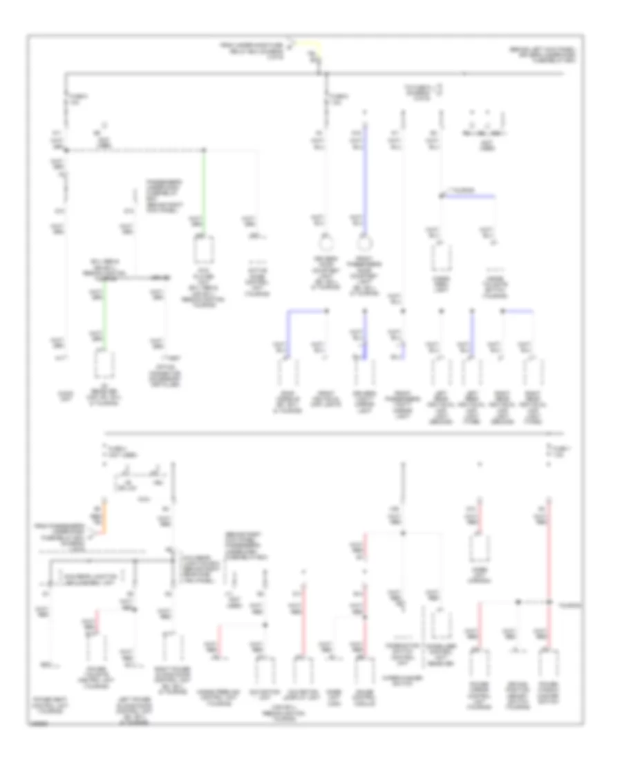
Power Distribution Wiring Diagram (3 of 6) for Honda Odyssey EX 2008
 https://portal-diagnostov.com/license.html
Automotive Electricians Portal FZCO
Automotive Electricians Portal FZCO
https://portal-diagnostov.com/license.html
https://portal-diagnostov.com/license.html
Automotive Electricians Portal FZCO
Automotive Electricians Portal FZCOList of elements for Power Distribution Wiring Diagram (3 of 6) for Honda Odyssey EX 2008:
- (behind left kick panel) driver's under-dash fuse/relay box
- (behind right kick panel) passenger's under-dash fuse/relay box
- (diagram 1 of 6)
- (not used)
- (usa ex-l: res/navigation, touring)
- +b dr lck
- 10a
- 7.5a
- A11
- A17
- A37
- Active noise control unit (touring)
- Audio unit
- B10
- C607
- Cargo area light
- Combination switch control unit
- D10
- D11
- D12
- D13
- Driver's door courtesy light (ex, ex-l & touring)
- Driver's vanity mirror light
- Driving position memory switch (touring)
- Dvd player unit (ex-l res & usa ex-l: res/navigation, touring)
- E14
- Ex-l res & usa ex-l: res/navigation, touring
- From passenger's under-dash fuse/relay box f
- From under-hood fuse/ q relay box (diagram 2 of 6)
- Front individual map lights
- Front passenger's door courtesy light (ex, ex-l & touring)
- Front passenger's vanity mirror light
- Fuse 5
- Fuse 6
- Fuse 7
- Fuse 8
- Gauge control module
- Hands freelink control unit (touring)
- Immobilizer control unit- receiver
- Imoes unit (canada)
- Imoes unit (usa)
- Inside tailgate switch (touring)
- J11 (not used)
- Left power sliding door control unit (ex, ex-l & touring)
- Left rear individual map light (second)
- Left rear individual map light (third)
- Micu
- Micu-rear junction box (behind right rear side trim panel)
- Micu-rear junction box control unit
- N11
- N15
- Navigation display unit
- Navigation unit
- Option connector (accessory installed)
- Passenger's under-dash fuse/relay box (behind right kick panel)
- Power mirror control unit (touring)
- Power seat control unit (touring)
- Power tailgate control unit (touring)
- Power window master switch
- Right power sliding door control unit (ex, ex-l & touring)
- Right rear individual map light (second)
- Right rear individual map light (third)
- Roof console (ex, ex-l & touring)
- To fuse 9 (diagram 5 of 6)
- Touring
- Usa: ex
- Vbu
- Wiper/washer switch
- X22
- X35
- Xm receiver (usa: ex, ex-l & touring)
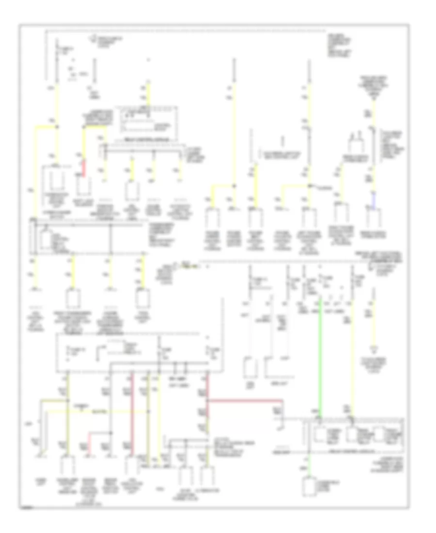
Power Distribution Wiring Diagram (4 of 6) for Honda Odyssey EX 2008
 https://portal-diagnostov.com/license.html
Automotive Electricians Portal FZCO
Automotive Electricians Portal FZCO
https://portal-diagnostov.com/license.html
https://portal-diagnostov.com/license.html
Automotive Electricians Portal FZCO
Automotive Electricians Portal FZCOList of elements for Power Distribution Wiring Diagram (4 of 6) for Honda Odyssey EX 2008:
- (behind left kick panel) driver's under-dash fuse/relay box
- (not
- (not used)
- 10a
- 15a
- 20a 10a
- 30a
- 7.5a
- A12
- A14
- A17
- A18
- A35
- Acm control relay (ex-l & touring)
- Acm control unit (ex-l & touring)
- Alternator
- Automatic lighting control unit (touring)
- B42
- Brake pedal position switch
- C14
- Canada
- Combination switch control unit
- Control block
- Driver's under-dash fuse/relay box (behind left kick panel)
- Drl control unit (usa)
- Eld unit
- Engine mount control solenoid valve (lx, ex, & canada: dx)
- Evap canister purge valve
- From driver's under-dash fuse/relay box (diagram 4 of 6)
- From fuse 20 (diagram 4 of 6)
- From ignition switch (diagram 2 of 6)
- Front passenger's power window switch/ door lock switch (ex, ex-l & touring)
- Front washer motor relay
- Fuse
- Fuse 10
- Fuse 19
- Fuse 21
- Gauge control module
- Hazard warning switch/front passenger's airbag cut- off indicator
- Ig1
- Immobilizer control unit- receiver
- Imoes unit
- Intermi- ttent wiper relay
- J/c c103 (ex-l & touring: rear of engine) (ex & lx: top of transmission)
- J/c c503 (under left side of dash)
- J10
- Left power sliding door control unit (ex, ex-l & touring)
- Micu
- Micu-rear junction box (behind right rear side trim panel)
- Micu-rear junction box control unit
- N29
- N41
- Ods unit
- Parking/ back-up sensor switch (touring)
- Passenger's under-dash fuse/relay box (behind right kick panel)
- Pcm
- Pgm-fi main relay 2
- Power mirror control unit (touring)
- Power seat control unit (touring)
- Power tailgate control unit (touring)
- Power window master switch
- Rear washer motor relay
- Rear window wiper motor
- Rear window wiper relay
- Red
- Relay control module
- Right power sliding door control unit (ex, ex-l & touring)
- Shift lock solenoid
- Srs unit
- To fuse 21 (diagram 4 of 6)
- To micu-rear junction box (diagram 4 of 6)
- Touring
- Tpms control unit
- Under-hood fuse/relay box (right rear of engine compt)
- Usa
- Used)
- Vsa modulator control unit
- Windshield wiper motor
- Wiper/washer switch
- X16
- X17
- X20
- X34
- X38
Power Distribution Wiring Diagram (5 of 6) for Honda Odyssey EX 2008
 https://portal-diagnostov.com/license.html
Automotive Electricians Portal FZCO
Automotive Electricians Portal FZCO
https://portal-diagnostov.com/license.html
https://portal-diagnostov.com/license.html
Automotive Electricians Portal FZCO
Automotive Electricians Portal FZCOList of elements for Power Distribution Wiring Diagram (5 of 6) for Honda Odyssey EX 2008:
- (behind left kick panel) driver's under-dash fuse/relay box
- (behind right kick panel) passenger's under-dash fuse/relay box
- (ex-l, touring)
- (ex-l: res, usa ex-l: res/navigation & touring)
- (not used)
- (option connector)
- (usa ex-l: res/navigation, touring)
- +b hazard
- 10a
- 15a
- 20a
- 30a
- 7.5a
- A/c control panel (lx, canada: dx)
- A11
- Acc
- Audio unit
- Automatic dimming inside mirror (usa ex-l: res/navigation, touring)
- Automatic lighting control unit (touring)
- Auxiliary headphone jack assembly
- Brake pedal position switch
- Climate control panel
- Climate control unit
- D14
- D15
- D16
- D17
- Driver's accessory power socket
- Driver's accessory power socket relay
- Driver's under-dash fuse/relay box (behind left kick panel)
- Dvd player unit
- Ex, ex-l & touring
- From battery (diagram 1 of 6)
- From driver's under-dash fuse/relay box (diagram 2 of 6)
- From fuse 12 (diagram 1 of 6)
- From fuse 6 (diagram 3 of 6)
- From ignition switch (diagram 2 of 6)
- From multi-fuse 23 (diagram 2 of 6)
- Fuse 13 20a
- Fuse 16
- Fuse 17
- Fuse 18
- Fuse 27
- Fuse 28 (ex-l & touring) 20a
- Fuse 32
- Fuse 4 15a
- Fuse 9
- G501 (under left side of dash)
- G601 (behind left kick panel)
- Handsfreelink control unit (touring)
- Hazard warning switch/front passenger's airbag cut-off indicator
- High beam headlight relay
- Horn relay
- Ignition key switch/key light
- J/c c503 (under left side of dash)
- Low beam headlight relay
- Micu
- Micu-rear junction box (behind right rear side trim panel)
- Moonroof close relay
- Moonroof open relay
- N36
- N39
- N45
- Navigation display unit
- Navigation unit
- Power window master switch
- Power window relay
- Rear a/c control panel (lx) rear climate control panel (ex, ex-l & touring)
- Rearview monitor mirror (ex-l, ex-l: res)
- Recirculation control motor
- Red
- Relay control module
- Seat heater relay (ex-l & touring)
- Taillight relay
- Touring
- Trailer lighting control unit (accessory installed)
- Trailer lighting in-line fuse
- Turn signal/ hazard relay
- Under-hood fuse/relay box (right rear of engine compt)
- Vsa modulator control unit
- X14
- X24
- X39
Power Distribution Wiring Diagram (6 of 6) for Honda Odyssey EX 2008
 https://portal-diagnostov.com/license.html
Automotive Electricians Portal FZCO
Automotive Electricians Portal FZCO
https://portal-diagnostov.com/license.html
https://portal-diagnostov.com/license.html
Automotive Electricians Portal FZCO
Automotive Electricians Portal FZCOList of elements for Power Distribution Wiring Diagram (6 of 6) for Honda Odyssey EX 2008:
- (ex-l & touring)
- (not used)
- 15a
- 7.5a
- Adjustable pedal forward relay
- Adjustable pedal rearward relay
- Auxiliary under-hood relay box
- B12
- Canada
- Cargo area accessory power socket
- Cargo area accessory power socket relay
- Ckp sensor
- Ckp sensors (a & b) (lx, ex & canada;dx)
- Cmp sensor
- D10
- D14
- D16
- Data link connector (dlc)
- Day lt
- Driver's power seat adjustment switch
- Driver's under-dash fuse/relay box (behind left kick panel)
- Drl control unit
- Drl relay
- Etcs control relay
- Ex & ex-l
- F11
- F13
- From under-hood fuse/relay box (diagram 1 of 6)
- From under-hood fuse/relay box (diagram 2 of 6)
- Fuel injector
- Fuse 1 7.5a
- Fuse 12
- Fuse 13 (ex, ex-l & touring) 20a
- Fuse 14 (ex, ex-l & touring) 20a
- Fuse 15 (touring) 20a
- Fuse 16 (ex, ex-l & touring) 20a
- Fuse 17 (touring) 20a
- Fuse 2
- Fuse 23
- Fuse 3 10a
- Fuse 4
- G652 (behind right rear side trim panel)
- G702 (behind left rear side trim panel)
- Ignition coil relay
- J/c c101 (right side of engine)
- J1 (not used)
- Left power sliding door control unit (ex, ex-l & touring)
- Maf sensor (lx, ex & canada: dx) maf/iat sensor (ex-l, touring)
- Micu
- Micu-rear junction box (behind right rear side trim panel)
- Micu-rear junction box control unit
- N10
- N40
- Passenger's under-dash fuse/relay box (behind right kick panel)
- Pcm
- Pgm-fi main relay 1
- Pgm-fi sub- relay (laf)
- Power adjustable pedal switch
- Power seat control unit
- Power tailgate control unit
- Radiator fan diode (under left side of dash)
- Radiator fan relay
- Red
- Touring
- Tpms control unit
- Under-hood fuse/relay box (right rear of engine compt)
- Usa
- X12
- X15
- X23
- X26 (not used)
- X31

 Čeština
 Dansk
Dansk Deutsch
 Ελληνικά
 English
 English
 Español
 Suomi
Suomi Français
 Français
 עברית
עברית Hrvatski
 Magyar
 Italiano
 日本語
日本語 한국어
한국어 Nederlands
 Polski
 Português
 Português
 Română
 Русский
 Slovenčina
 Slovenščina
 Svenska
 Türkçe
