SUPPLEMENTAL RESTRAINTS
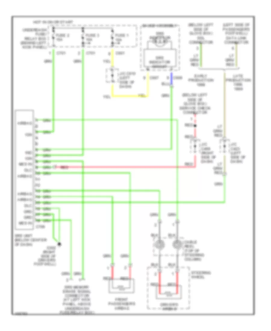
Supplemental Restraint Wiring Diagram for Honda Odyssey LX 1998
 https://portal-diagnostov.com/license.html
Automotive Electricians Portal FZCO
Automotive Electricians Portal FZCO
https://portal-diagnostov.com/license.html
https://portal-diagnostov.com/license.html
Automotive Electricians Portal FZCO
Automotive Electricians Portal FZCO
List of elements for Supplemental Restraint Wiring Diagram for Honda Odyssey LX 1998:
- (below left side of glove box) sdl connector
- (below left side of glove box) service check connector
- (left side of passenger's footwell) data link connector
- Airbag
- C601
- C607
- C609
- C701
- C706
- Cable reel (top of steering column)
- Dlc
- Driver's airbag
- Early production
- Front passenger's airbag
- Fuse 1 10a
- Fuse 2 15a
- Fuse 3 10a
- G302 (right side of driver's footwell)
- Gauge assembly
- Grd
- Hot in on or start
- Ign
- Ind
- J/c c423 (left side of dash)
- J/c c469 (right side of dash)
- J/c c610 (left side of dash)
- Late production 1998,
- Mes in
- Red
- Srs indicator
- Srs indicator circuit
- Srs memory erase signal connector (at left kick panel, above underdash fuse/relay box)
- Srs unit (below center of dash)
- Steering wheel
- Underdash fuse/ relay box (behind left kick panel)
 Čeština
 Dansk
Dansk Deutsch
 Ελληνικά
 English
 English
 Español
 Suomi
Suomi Français
 Français
 עברית
עברית Hrvatski
 Magyar
 Italiano
 日本語
日本語 한국어
한국어 Nederlands
 Polski
 Português
 Português
 Română
 Русский
 Slovenčina
 Slovenščina
 Svenska
 Türkçe
 中文 (中国)
