ENGINE PERFORMANCE
3.5L
3.5L, Engine Performance Wiring Diagram (1 of 5) for Lexus ES 350 2014
 https://portal-diagnostov.com/license.html
Automotive Electricians Portal FZCO
Automotive Electricians Portal FZCO
https://portal-diagnostov.com/license.html
https://portal-diagnostov.com/license.html
Automotive Electricians Portal FZCO
Automotive Electricians Portal FZCO
List of elements for 3.5L, Engine Performance Wiring Diagram (1 of 5) for Lexus ES 350 2014:
- (left "c" pillar) p1
- (left kick panel) j/c a61
- (pins: 38 to 40 not used)
- +b2
- A/f fuse 20a
- A/f htr relay
- A1 (behind left headlamp assembly)
- A22
- A36
- Accelerator pedal sensor assembly (on accelerator pedal)
- Acm
- Anti-theft system
- Ap1
- Batt
- C10
- Canh
- Canl
- Cchg
- Ccs
- Certification ecu (right side of dash)
- Computer data lines system
- Cooling fans system
- Cruise control system
- Da2
- Efi 1 fuse 7.5a
- Efi 2 fuse 15a
- Efi 3 fuse 10a
- Efi main 1 fuse 30a
- Efi main relay
- Engine control module (left side of engine compt)
- Engine room j/b (left front of engine compt)
- Engine room r/b (left side of engine compt)
- Epa
- Epa2
- Fp-
- Fpc
- Fuel pump control ecu (left side of luggage compt)
- Fuel suction w/ pump & gage tube assembly (fuel tank assembly)
- Gage
- H1 (center of dash)
- Ha2
- Ha4
- Hot at all times
- Igsw
- Imi
- Imo
- Instrument cluster system
- Integration control & panel assembly
- J/c a63 (behind left front headlight assembly)
- Lgnd
- Mpmp
- Mrel
- Neo
- Normal mode
- Pnk
- Ppmp
- Pump m
- Pwms
- Red
- Rfc
- Sftd
- Sftu
- Spcn
- Spd
- Sports mode
- St1-
- Sta
- Starting/charging system
- Stp
- Tach
- Transmission control ecu (left side of transmission)
- Transmissions system
- Vcp2
- Vcpa
- Vpa
- Vpa2
- Vpmp
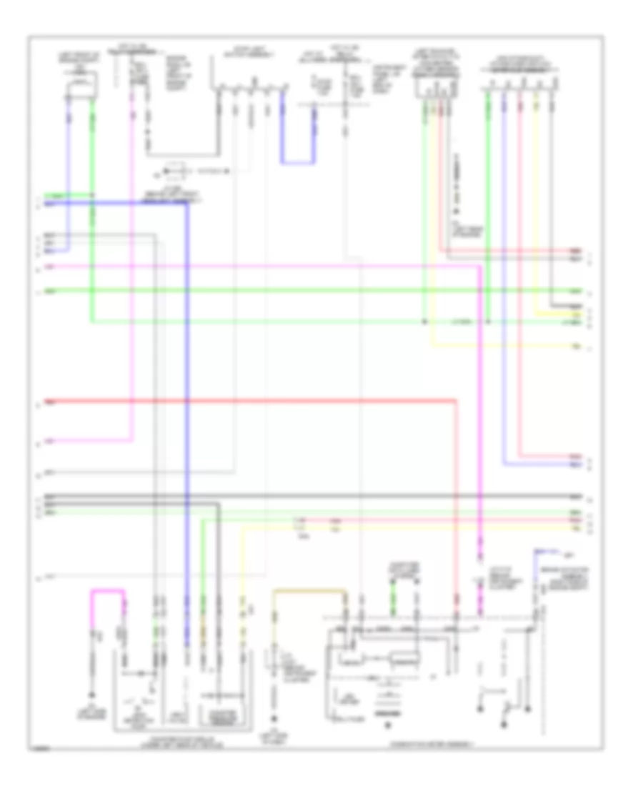
3.5L, Engine Performance Wiring Diagram (2 of 5) for Lexus ES 350 2014
 https://portal-diagnostov.com/license.html
Automotive Electricians Portal FZCO
Automotive Electricians Portal FZCO
https://portal-diagnostov.com/license.html
https://portal-diagnostov.com/license.html
Automotive Electricians Portal FZCO
Automotive Electricians Portal FZCOList of elements for 3.5L, Engine Performance Wiring Diagram (2 of 5) for Lexus ES 350 2014:
- (air intake duct) intake mass air flow meter sub-assembly
- (left exhaust, after catalytic converter) oxygen sensor (bank 2 sensor 2)
- (left front of engine compt) vsv (acm)
- 5v ic
- A17
- Ap1
- Brake actuator assembly (right side of engine compt)
- Can i/f
- Canh
- Canister pressure sensor
- Canister pump module (under left rear of vehicle)
- Canl
- Chk
- Combination meter assembly
- Computer data lines system
- Cpu
- D3 (left rear of engine)
- D30
- D4 (left side of engine)
- Da2
- E2g
- Ecu ig2 1 fuse 7.5a
- Ecu ig2 3 fuse 7.5a
- Engine room j/b (left front of engine compt)
- Gnd
- H14
- H4 (left side of dash)
- Ha8
- Hot at all times
- Hot w/ ig2 relay energized
- Ht2b
- I/f
- Ig+
- Instrument panel j/b (left end of dash)
- J/c a63 (behind left front headlight assembly)
- J/c h107 (behind instrument cluster)
- J/c h115 (behind instrument cluster)
- Leak detection pump
- Led driver
- Mgnd
- Mtrb
- Ox2b
- Pnk
- Red
- Sgnd
- Shield
- Sp1
- Speaker
- Stop fuse 7.5a
- Stop light switch assembly
- Telltales
- Tha
- Vcc
- Vent valve
- Vgnd
- Vlvb
- Vout
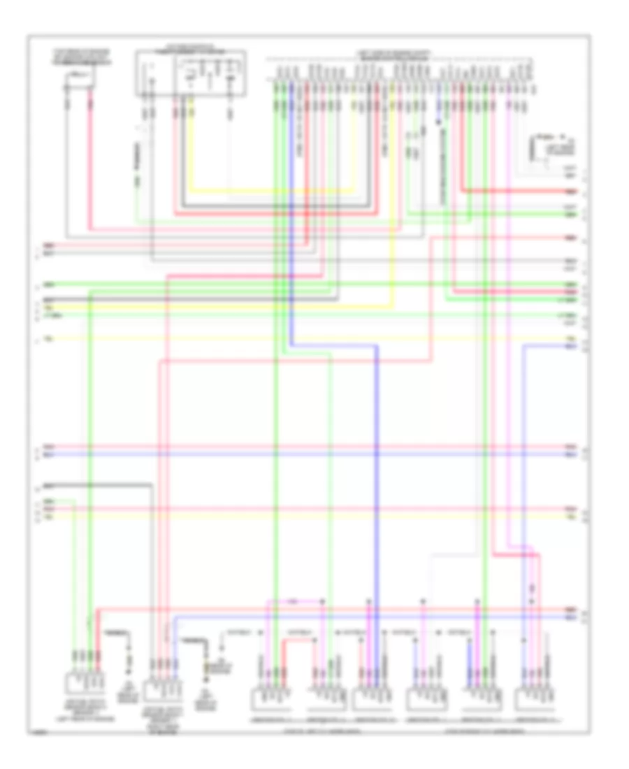
3.5L, Engine Performance Wiring Diagram (3 of 5) for Lexus ES 350 2014
 https://portal-diagnostov.com/license.html
Automotive Electricians Portal FZCO
Automotive Electricians Portal FZCO
https://portal-diagnostov.com/license.html
https://portal-diagnostov.com/license.html
Automotive Electricians Portal FZCO
Automotive Electricians Portal FZCOList of elements for 3.5L, Engine Performance Wiring Diagram (3 of 5) for Lexus ES 350 2014:
- (intake manifold) throttle body w/ motor
- (left rear of engine)
- (left side of engine compt) engine control module
- (pins: 119 to 124 not used)
- (pins: 135 to 137 not used)
- (top of left cylinder head)
- (top of right cylinder head)
- (top rear of engine) efi engine coolant temperature sensor
- A1a+
- A1a-
- A2a+
- A2a-
- Air fuel ratio sensor (bank 1 sensor 1) (right rear of engine)
- Air fuel ratio sensor (bank 2 sensor 1) (left rear of engine)
- Alt
- D23
- D3 (left rear of engine)
- D6 (rear of engine)
- Da2
- E2g
- Ekn2
- Eknk
- Eta
- Etha
- Ethw
- Ex1b
- Ex2b
- Ge01
- Gnd
- Ha1a
- Ha2a
- Ic1
- Ic2
- Igf
- Igf1
- Ignition coil 1
- Ignition coil 2
- Ignition coil 3
- Ignition coil 4
- Ignition coil 5
- Ignition coil 6
- Igt1
- Igt2
- Igt3
- Igt4
- Igt5
- Igt6
- Ne-
- Ox1b
- Ox2b
- Pnk
- Red
- Shield
- Starting/charging system
- Thw
- Vcta
- Vcv1
- Vta1
- Vta2
- Vv1-
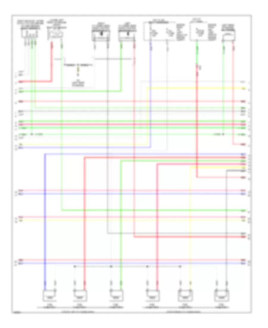
3.5L, Engine Performance Wiring Diagram (4 of 5) for Lexus ES 350 2014
 https://portal-diagnostov.com/license.html
Automotive Electricians Portal FZCO
Automotive Electricians Portal FZCO
https://portal-diagnostov.com/license.html
https://portal-diagnostov.com/license.html
Automotive Electricians Portal FZCO
Automotive Electricians Portal FZCOList of elements for 3.5L, Engine Performance Wiring Diagram (4 of 5) for Lexus ES 350 2014:
- (left cylinder head) knock control sensor (bank 2)
- (left front of engine compt)
- (left rear of engine) vsv (purge)
- (lower left front of engine) crank position sensor
- (right cylinder head) knock control sensor (bank 1)
- (right exhaust, after catalytic converter) oxygen sensor (bank 1 sensor 2)
- (top of left cylinder head)
- (top of right cylinder head)
- D3 (left rear of engine)
- Da2
- Engine room j/b
- Engine room r/b (left side of engine compt)
- Etcs fuse 10a
- Fuel injector 1
- Fuel injector 2
- Fuel injector 3
- Fuel injector 4
- Fuel injector 5
- Fuel injector 6
- Hot at all times
- Hot w/ ig2 relay energized
- Ht1b
- Ign fuse 15a
- Inj fuse 7.5a
- Ox1b
- Pnk
- Red
- Shield
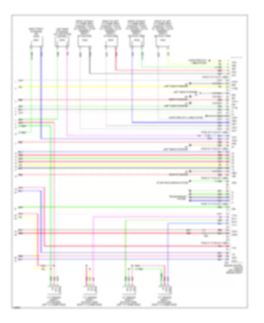
3.5L, Engine Performance Wiring Diagram (5 of 5) for Lexus ES 350 2014
 https://portal-diagnostov.com/license.html
Automotive Electricians Portal FZCO
Automotive Electricians Portal FZCO
https://portal-diagnostov.com/license.html
https://portal-diagnostov.com/license.html
Automotive Electricians Portal FZCO
Automotive Electricians Portal FZCOList of elements for 3.5L, Engine Performance Wiring Diagram (5 of 5) for Lexus ES 350 2014:
- (front of left cylinder head) camshaft timing oil control valve assembly (bank 2 exhaust side)
- (front of left cylinder head) camshaft timing oil control valve assembly (bank 2 intake side)
- (front of right cylinder head) camshaft timing oil control valve assembly (bank 1 exhaust side)
- (front of right cylinder head) camshaft timing oil control valve assembly (bank 1 intake side)
- (left rear of engine)
- (left rear of engine) vsv (air intake control)
- (pins: 36 to 45 not used)
- (pins: 50 to 52 not used)
- (pins: 6 to 19 not used)
- (pins: 61 to 64 not used)
- (pins: 72 to 75 not used)
- (pins: 87 to 95 not used)
- (right front of engine) vsv (acis)
- +bm
- A1a+
- A2a+
- Acis
- Aicv
- Can+
- Can-
- Computer data lines system
- D23
- D3 (left rear of engine)
- D4 (left side of engine)
- D6 (rear of engine)
- Da2
- Da2
- E01
- E02
- E04
- E05
- Engine control module (left side of engine compt)
- Ev1+
- Ev2+
- Ex+
- Ex-
- Ha1a
- Ha2a
- Ht1b
- Ht2b
- Knk1
- Knk2
- Me01
- Ne+
- Nsw
- Oc1+
- Oc1-
- Oc2+
- Oc2-
- Oe1+
- Oe1-
- Oe2+
- Oe2-
- Pnk
- Prg
- Red
- Starting/charging system
- Tha
- Transmissions system
- Vc2
- Vv1+
- Vv2+
- Vvl+
- Vvl-
- Vvr+
- Vvr-
- Vvt sensor (bank 1 exhaust side) (right cylinder head)
- Vvt sensor (bank 1 intake side) (right cylinder head)
- Vvt sensor (bank 2 exhaust side) (left cylinder head)
- Vvt sensor (bank 2 intake side) (left cylinder head)

 Čeština
 Dansk
Dansk Deutsch
 Ελληνικά
 English
 English
 Español
 Suomi
Suomi Français
 Français
 עברית
עברית Hrvatski
 Magyar
 Italiano
 日本語
日本語 한국어
한국어 Nederlands
 Polski
 Português
 Português
 Română
 Русский
 Slovenčina
 Slovenščina
 Svenska
 Türkçe
