ENGINE PERFORMANCE
4.0L
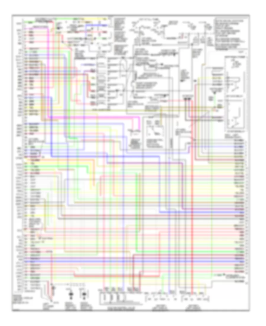
4.0L, Engine Performance Wiring Diagrams (1 of 3) for Lexus SC 400 1997
 https://portal-diagnostov.com/license.html
Automotive Electricians Portal FZCO
Automotive Electricians Portal FZCO
https://portal-diagnostov.com/license.html
https://portal-diagnostov.com/license.html
Automotive Electricians Portal FZCO
Automotive Electricians Portal FZCO
List of elements for 4.0L, Engine Performance Wiring Diagrams (1 of 3) for Lexus SC 400 1997:
- center of i/p)
- #10 #10 #10
- #20 #20 #20
- #30 #30 #30
- #40 #40 #40
- #50
- #60
- #60 #60
- #70
- (eng harn, top right front of eng)
- (eng harn, top right front of engine) e25
- (i/p harn behind glove box)
- (i/p harn, behind glove box)
- (i/p harn, behind top right dash)
- (left
- (left cyl head)
- (left cylinder head)
- (left side of engine compt)
- (left side of front fender) g100
- (on
- (on trans-
- (rear of eng)
- (right
- (top left on eng)
- +b2
- Acc
- Am1
- Am2
- Bk/wh
- Bu/rd
- Bu/rd bu/rd
- Camshaft position sensor 1 (left front of engine)
- Camshaft position sensor 2 (right front of engine)
- Conn e12
- Crankshaft position sensor (lower left of engine)
- Cylinder
- Distributor
- E01
- E02
- E11
- E11 (engine harness, top left center of engine)
- E12
- E12 (engine harness, top center of firewall)
- E13
- E13 (engine harness, top right center of engine)
- E16
- E25
- Efi fuse 30a
- Efi main relay
- Egr1
- Egr2
- Egr3
- Engine control module (behind
- Evg
- Fuel injectors
- G1 g1 g1
- G1-
- G115
- G117
- G2 g2 g2
- G2-
- Head)
- Hot at all times
- Htl1
- Htl4
- Htr1
- Htr2
- Htl2
- I13
- I21
- I25
- I26
- I28
- I28 (i/p harn, behind center console)
- Idl1
- Idl2
- Idle air control valve (top center of engine)
- Igf
- Igf1
- Igf2
- Ign fuse 7.5a
- Igniter 1
- Igniter 2
- Ignition coil 1 (left front of eng)
- Ignition coil 2 (right front of engine)
- Ignition switch
- Igt
- Igt1
- Igt2
- Instrument cluster
- Instrument cluster system
- Isc1 isc1
- Isc2 isc2
- Isc3 isc3
- Isc4 isc4
- J/b 1 (left kick panel)
- Knk1
- Knk2
- Knock sensor 1 (left top of engine)
- Knock sensor 2 (right top of engine)
- Lock
- Mission)
- Nco
- Nco-
- Ne ne
- Ne- ne-
- Noise filter
- Note: splice locations e8 (engine harness, top of left front fender)
- Nsw
- O/d direct clutch speed sensor
- Oil
- On ig2
- Oxl1
- Oxl2
- Oxr1
- Oxr2
- P/n
- Park/neutral position switch transmission)
- Pnk
- Pnk pnk
- Prg
- R/b 2 engine compt)
- Red
- Red red
- Red red red
- Short connector (center rear of engine compt)
- Sln+
- Sln-
- Slu+
- Slu-
- Sp2
- Sp2-
- St fuse 7.5a
- St1
- Sta
- Start
- Starter relay
- Starting system
- Stj
- Tach
- Tha
- Thg
- Thw
- Vc vc
- Vehicle speed sensor 2
- Vf1 vf1
- Vf2 vf2
- Vta1 vta1
- Vta2 vta2
- W/o trac
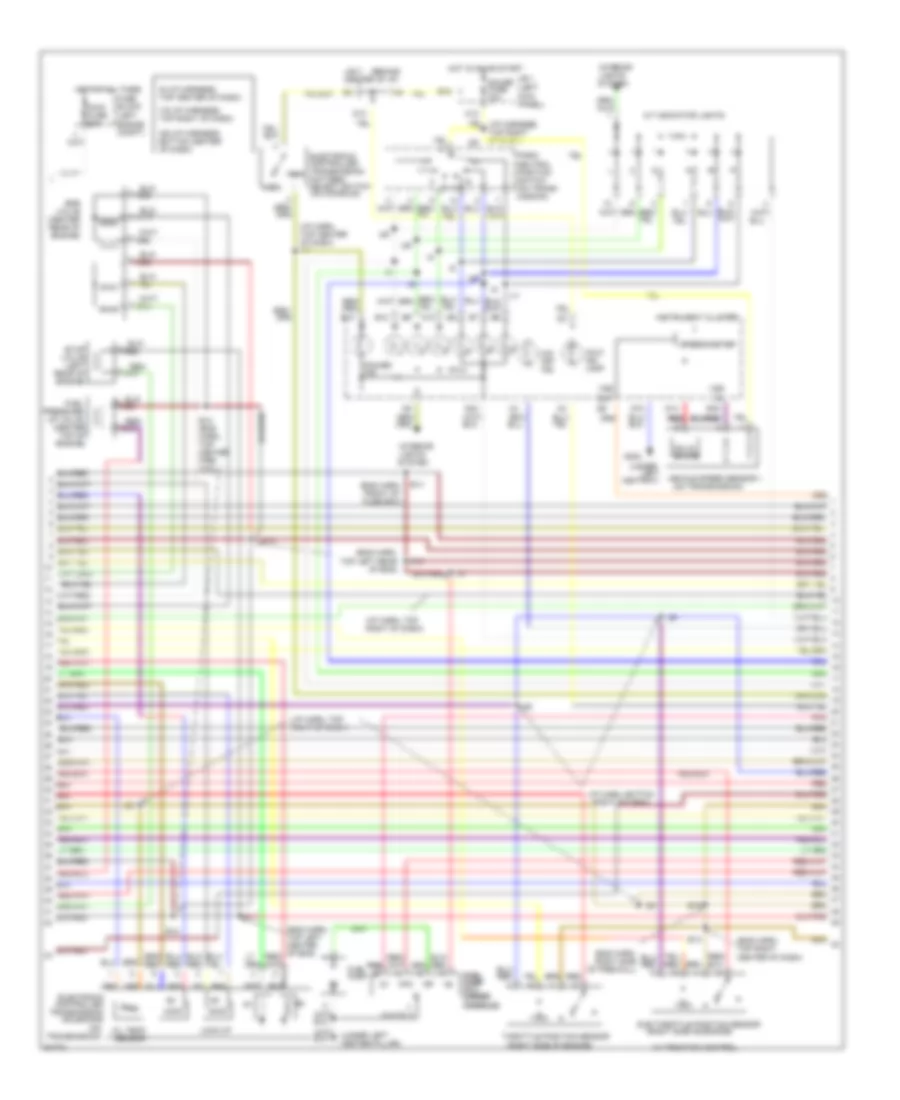
4.0L, Engine Performance Wiring Diagrams (2 of 3) for Lexus SC 400 1997
 https://portal-diagnostov.com/license.html
Automotive Electricians Portal FZCO
Automotive Electricians Portal FZCO
https://portal-diagnostov.com/license.html
https://portal-diagnostov.com/license.html
Automotive Electricians Portal FZCO
Automotive Electricians Portal FZCOList of elements for 4.0L, Engine Performance Wiring Diagrams (2 of 3) for Lexus SC 400 1997:
- (behind
- (eng harn, front of fuse box)
- (eng harn, top left center of eng)
- (eng harn, top left rear of eng)
- (eng harn, top right center of dash)
- (i/p harn, bottom right of dash)
- (i/p harn, top center of dash) i17
- (i/p harn, top right of dash)
- (i/p harness, top right of dash)
- (left
- (on
- (on transmission)
- (right side of engine)
- (under
- (under left center pillar)
- A/t indicator lights
- A10
- Ashtray)
- B12
- C2 c2
- D10
- D13
- D13 d13
- D14
- E e
- E11
- E12
- E12 (eng harn, top center fire- wall)
- E13
- E14
- E15
- E16
- Egr valve (center rear of engine)
- Electronic controlled
- Electronic controlled transmission pattern select switch (on console)
- Engine compt)
- Evap valve (left rear of engine)
- Fp fp
- Fpc
- Fuel fuel pump pump ecu (under (under console) console)
- Fuel pressure up valve (center top of engine)
- Fuel pump
- Fuse block
- G302
- Gauge fuse 10a
- H12
- Hot at all times
- Hot in on or start
- I17
- I19
- I19 (i/p harness, top right of dash)
- I25
- I26
- I28
- I29
- I29 (i/p harness, bottom center of dash)
- I9 (i/p harness, top center of dash)
- Instrument cluster
- Interior
- J/b 1 (left
- J/b 3 center of i/p)
- Kick panel)
- Left
- Lights system
- Lock-up
- Main fuse 60a
- Malf. ind. lamp
- Norm
- O/d off ind.
- Oil temp. sensor
- Out
- Park/ neutral position switch (on trans- mission)
- Pnk pnk
- Power ind.
- Pwr
- Red
- Red red red
- Red/
- Solenoids
- Solid state
- Speedometer
- Sub throttle position sensor
- Throttle position sensor
- Transmission
- Transmission)
- Vehicle speed sensor 1
- Vss
- W/ traction control
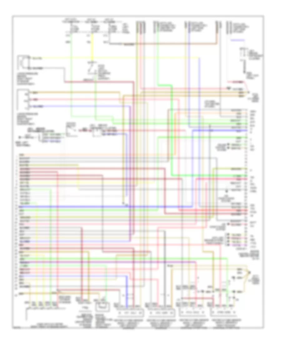
4.0L, Engine Performance Wiring Diagrams (3 of 3) for Lexus SC 400 1997
 https://portal-diagnostov.com/license.html
Automotive Electricians Portal FZCO
Automotive Electricians Portal FZCO
https://portal-diagnostov.com/license.html
https://portal-diagnostov.com/license.html
Automotive Electricians Portal FZCO
Automotive Electricians Portal FZCOList of elements for 4.0L, Engine Performance Wiring Diagrams (3 of 3) for Lexus SC 400 1997:
- (behind
- (behind (behind
- (center rear
- (i/p harn, top center of dash)
- (left
- (left kick panel
- (right front of engine compt)
- A/c
- A/d
- Acmg
- Air
- Air conditioning system
- Anti-lock brakes system (traction ecu)
- Batt
- C13
- Compt)
- Conditioning
- Conn e11
- Control
- Cruise
- Cylinder
- D10
- Data link connector 1 (center top of engine)
- Data link connector 2 (left side of dash)
- Data link connector 3 (left side of dash)
- E15
- E16
- Egr gas
- Els
- Engine control module (behind center of i/p)
- Engine coolant temperature sensor (right front of engine)
- Fpc
- G115 left
- G117 (right
- G200 (left kick panel)
- G200 g200
- Head)
- Heated oxygen sensor (bank 1, sensor 1) (left exhaust manifold)
- Heated oxygen sensor (bank 1, sensor 2) (left exhaust manifold, after twc)
- Heated oxygen sensor (bank 2, sensor 1) (right exhaust manifold)
- Heated oxygen sensor (bank 2, sensor 2) (right exhaust manifold, after twc)
- Hot at all times
- Hot with tail lights on
- Ht1
- Ht2
- Htl2
- Htr2
- I10
- I18
- I25
- I28
- I35
- Igsw
- J/b 1
- J/b 3 (behind instrument cluster)
- J/b 3 instrument cluster)
- J/b 3 j/b 3 instrument cluster) instrument cluster)
- K10
- Kick panel) kick panel)
- M-rel
- Mass air flow meter
- Neo
- O/d main switch
- Obdii fuse 7.5a
- Od1
- Od2
- Of engine
- Oxl1
- Oxl2
- Oxr1
- Oxr2
- Pim
- Pnk
- Ptnk
- Red
- Sdl
- Sensor
- Spd
- Stop fuse 15a
- Stop light switch (on brake pedal support)
- Stp
- System
- Tail fuse 7.5a
- Te1
- Temperature
- Tpc
- Vapor pressure sensor (right front of engine compartment)
- Vto1
- Vto2

 Čeština
 Dansk
Dansk Deutsch
 Ελληνικά
 English
 English
 Español
 Suomi
Suomi Français
 Français
 עברית
עברית Hrvatski
 Magyar
 Italiano
 日本語
日本語 한국어
한국어 Nederlands
 Polski
 Português
 Português
 Română
 Русский
 Slovenčina
 Slovenščina
 Svenska
 Türkçe
