POWER DISTRIBUTION
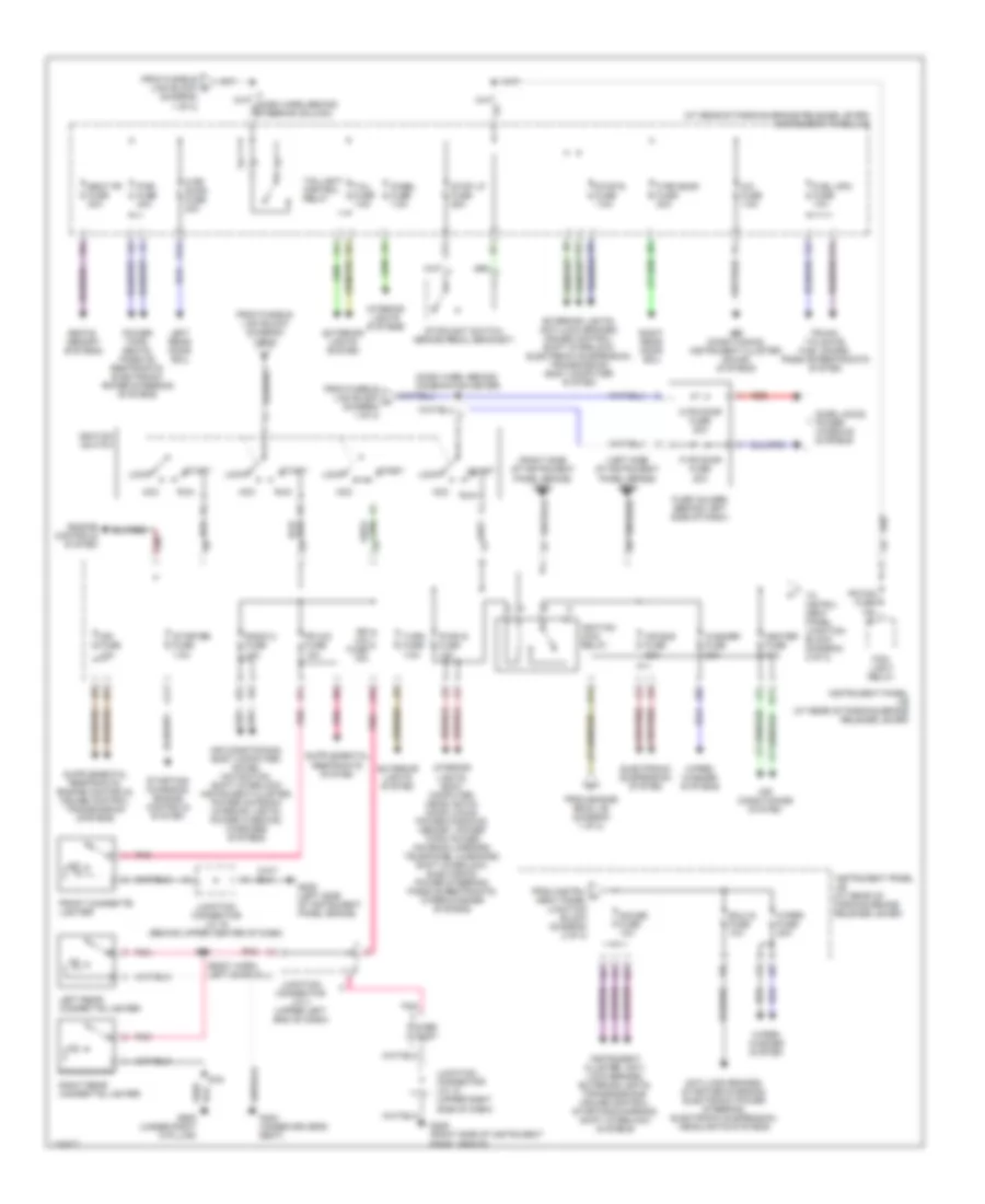
Power Distribution Wiring Diagram (1 of 2) for Lexus LS 400 2000
 https://portal-diagnostov.com/license.html
Automotive Electricians Portal FZCO
Automotive Electricians Portal FZCO
https://portal-diagnostov.com/license.html
https://portal-diagnostov.com/license.html
Automotive Electricians Portal FZCO
Automotive Electricians Portal FZCO
List of elements for Power Distribution Wiring Diagram (1 of 2) for Lexus LS 400 2000:
- (canada)
- (on left side of engine compt, forward of strut tower) engine room j/b
- (on left side of engine compt, forward of strut tower) engine room r/b
- (on left side of engine, room j/b strut tower)
- (usa)
- Abs fuse 60a
- Air conditioning, cooling fans systems
- Alt fuse 120a
- Alt-s fuse 7.5a
- Am1 fuse 40a
- Am2 fuse 30a
- Anti-lock brakes system
- Anti-lock brakes, headlights systems
- Battery
- Body computer, instrument cluster, electronic power steering, interior lights, passive restraints, warnings, power windows, door locks systems
- Cellular phones system
- Cir opn relay
- Coil
- Computer data lines system
- Cooling fans system
- Crt fuse 15a
- Defog fuse 50a
- Defog relay
- Defogger system
- Dimmer relay (usa)
- Dome fuse 10a
- Drl 2 relay (canada)
- Drl fuse (can) 10a
- Ecu-b fuse 7.5a
- Efi 1 fuse 20a
- Efi 2 fuse 10a
- Efi relay
- Electronic suspension system
- Electronic suspension, body computer, instrument cluster, interior lights, headlights, memory, sound, door locks systems
- Engine controls system
- Engine main relay
- Engine room j/b
- Engine room j/b (on left side of engine compt, forward of strut tower)
- Etcs fuse 15a
- Exterior lights system
- Fr s/htr fuse 15a
- From e engine room j/b (diagram 1 of 2)
- From f engine room j/b (diagram 1 of 2)
- From fusible link block (diagram 1 of 2)
- Fusible link block (on left side of engine compt, forward of strut tower)
- H/ctrl fuse 40a
- Haz fuse 10a
- Head lamp relay
- Headlights system
- Heater fuse 50a
- Heater relay
- Horn fuse 10a
- Horn relay
- J10
- K10
- L lwr h-lp fuse 15a
- L upr h-lp fuse 10a
- Main fuse 80a
- Mg clt relay
- Mir htr fuse 15a
- Mpx-b fuse 10a
- Navigation system
- Noise filter (rear window defogger)
- Obd fuse 7.5a
- R lwr h-lp fuse 15a
- R upr h-lp fuse 10a
- Radio 1 fuse 20a
- Rdi fan fuse 30a
- Red
- Seats system
- Short pin
- Sound, power antenna, navigation systems
- St fuse 30a
- Starter
- Starter relay
- Starting/ charging system
- Tel fuse 15a
- To engine room j/b (diagram 1 of 2)
- To engine room r/b (diagram 1 of 2)
- To ignition switch (diagram 2 of 2)
- To instrument panel j/b (diagram 2 of 2)
- To instrument panel junction block (diagram 2 of 2)
- Wiper/ washer system
Power Distribution Wiring Diagram (2 of 2) for Lexus LS 400 2000
 https://portal-diagnostov.com/license.html
Automotive Electricians Portal FZCO
Automotive Electricians Portal FZCO
https://portal-diagnostov.com/license.html
https://portal-diagnostov.com/license.html
Automotive Electricians Portal FZCO
Automotive Electricians Portal FZCOList of elements for Power Distribution Wiring Diagram (2 of 2) for Lexus LS 400 2000:
- (at rear of parking brake release lever) instrument panel j/b
- (body harn, left door sill)
- (dash harn, behind combination meter)
- (left side of instrument panel brace) g206
- (right side of instrument panel brace) g206
- A/c fuse 7.5a
- Acc
- Air air conditioning, instrument cluster, sound systems
- Air conditioning system
- Air conditioning, body computer, sound, navigation, shift interlock instrument cluster, power antenna interior lights, power windows, warnings systems
- Air sus fuse 20a
- Anti-lock brakes, starting/charging, electronic power steering, electronic suspension, headlights systems
- B16
- B28
- D fr door fuse 20a
- D rr door fuse 20a
- D11
- Door locks, power windows systems
- Ecu-ig fuse 10a
- Electronic suspension system
- Engine controls system
- Exterior lights system
- Exterior lights, anti-lock brakes, cruise control, shift interlock, electronic suspension, transmission body computer system
- F11
- Fog- light relay
- Fr cig fuse 15a
- Fr fog fuse 15a
- From engine room j/b (diagram 1 of 2)
- From fusible link block (diagram 1 of 2)
- From fusible link block a (diagram 1 of 2)
- From instru- h ment panel junction block (diagram 2 of 2)
- Front cigarette lighter
- Fuel opn fuse 10a
- Fuse holder (behind left side of dash)
- G206 (left side of instrument panel brace)
- G206 (right side of instrument panel brace)
- G300 (under driver's seat)
- G905 (under right c-pillar)
- Gauge fuse 10a
- Heater fuse 10a
- I10
- I12
- I13
- I14
- I7 (dash harn, behind steering column)
- Ign fuse 10a
- Ignition main relay
- Ignition switch
- Instrument cluster, anti- lock brakes, exterior lights, transmissions, cruise control, starting/charging, shift interlock systems
- Instrument panel j/b (at rear of parking brake release lever)
- Interior lights systems
- Interior lights, body computer, headlights, door locks, power windows, memory, power tops, power antenna, mirrors, telephone, warnings, shift interlock, electronic power steering, passive restraints, wiper/washer systems
- J11
- J16
- Junction connector j/c 16 (behind upper center of dash)
- Junction connector j/c 18 (upper right side of dash)
- Junction connector j/c 4 (upper left end of dash)
- K12
- L10
- L11
- L12
- Left rear cigarette lighter
- Left rear door ecu
- Lock
- P fr door fuse 20a
- P rr door fuse 20a
- Panel fuse 7.5a
- Pnk
- Power outlet
- Power tops, seats, passive restraints, electronic power steering systems
- Pwr fuse 30a
- Pwr-ig fuse 15a
- Radio 2 fuse 15a
- Red
- Right rear cigarette lighter
- Right rear door ecu
- Rr cig fuse 15a
- Run
- Seat fr fuse 30a
- Seats, memory systems
- Start
- Starter fuse 7.5a
- Starting/ charging, engine controls system
- Stop lp fuse 25a
- Stop-s fuse 7.5a
- Stoplight switch (brake pedal bracket)
- Tail fuse 7.5a
- Taillight control relay
- To instru- ment panel junction block (diagram 2 of 2)
- Trunk, tailgate, fuel doors, passive restraints system
- Turn fuse 7.5a
- Washer fuse 20a
- Wiper fuse 20a
- Wiper/ washer system
- Wiper/ washer systems

 Čeština
 Dansk
Dansk Deutsch
 Ελληνικά
 English
 English
 Español
 Suomi
Suomi Français
 Français
 עברית
עברית Hrvatski
 Magyar
 Italiano
 日本語
日本語 한국어
한국어 Nederlands
 Polski
 Português
 Português
 Română
 Русский
 Slovenčina
 Slovenščina
 Svenska
 Türkçe
