TRANSMISSION
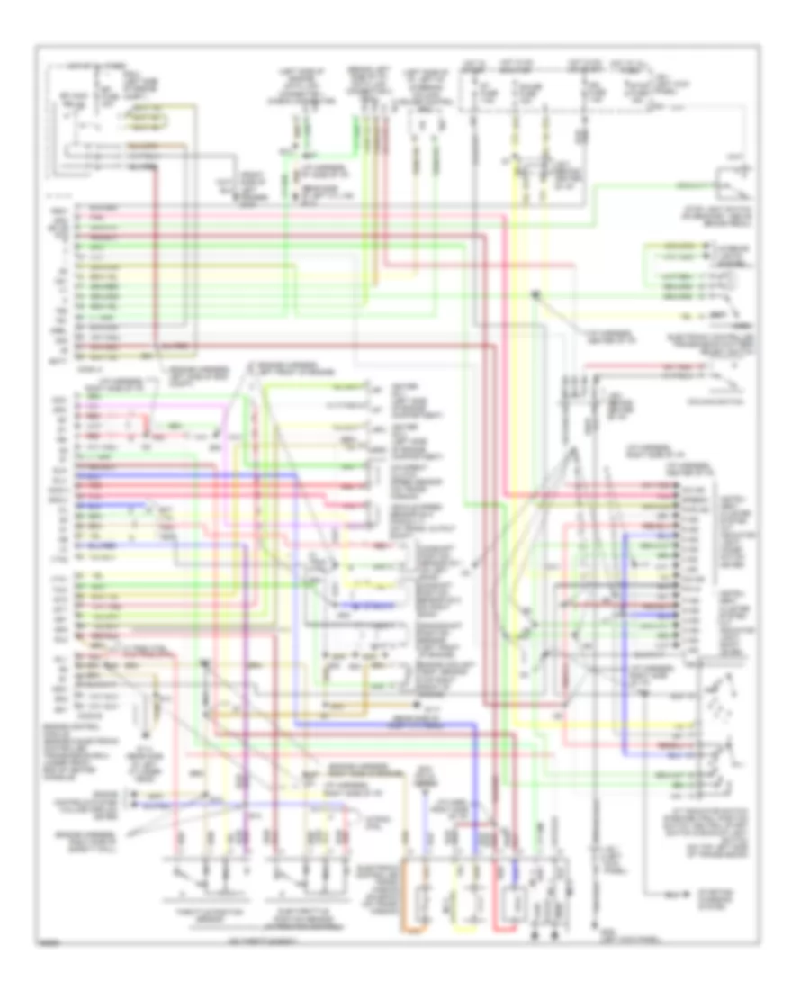
Transmission Wiring Diagram for Lexus SC 400 1995
 https://portal-diagnostov.com/license.html
Automotive Electricians Portal FZCO
Automotive Electricians Portal FZCO
https://portal-diagnostov.com/license.html
https://portal-diagnostov.com/license.html
Automotive Electricians Portal FZCO
Automotive Electricians Portal FZCO
List of elements for Transmission Wiring Diagram for Lexus SC 400 1995:
- (behind left side of i/p) data link connector 2 (tdcl)
- (engine harness, left front of engine)
- (engine harness, left side of eng compt)
- (engine harness, right side of engine)
- (engine harness, right side of safety wall)
- (front side of left fender) g100
- (i/p harn, right side of i/p)
- (i/p harness, center of i/p)
- (i/p harness, right side of i/p)
- (i/p harness, rt side of i/p)
- (left side of engine) data link connector 1 (check connector)
- (left side of i/p, left of steering column) cruise control ecu
- (lock-up) no.3
- (on throttle body)
- (rear side of left cyl hd) g114
- (rear side of right cyl head)
- 2 ind
- A/t indicator switch (park/neutral position switch, neutral start switch & backup light switch (on top left side of transmission)
- Batt
- Camshaft position sensor no.1 (on left bank) camshaft position sensor no.2 (on right bank)
- Conn a
- Conn b
- Crankshaft position sensor (left front of engine)
- D ind
- D13
- E12
- E13
- E17
- E18
- E21
- E30
- Ecm pin 24 conn b
- Ect
- Efi fuse 30a
- Efi main relay
- Electronic controlled trans- mission solenoid (on trans- mission)
- Electronic controlled transmission pattern select switch
- Engine control module (engine & electronic controlled transmission ecu) (under front end of center console)
- Engine controls system (volume airflow meter)
- Engine coolant temp. sensor (top right front of engine)
- Eo1
- Eo2
- G1-
- G114 (rear side of left cylinder head)
- G117
- G2-
- G200 (left kick panel)
- Gauge fuse 10a
- H12
- Hot at all times
- Hot in on or start
- Hot in start
- I10
- I16
- I17
- I26
- I27
- I29
- I32
- Idl
- Idl1
- Idl2
- Igf
- Igf1
- Igf2
- Ign fuse 7.5a
- Igniter no.1 (left side of engine compartment)
- Igniter no.2 (left side of engine compartment)
- Igsw
- Igt
- Igt1
- Igt2
- Instru- ment cluster system (a/t indicator light) (combi- nation meter)
- Instru- ment cluster system (a/t indicator light) (shift lever)
- Interior lights system
- J/b 1 (left kick panel)
- J/b 3 (behind center of i/p)
- L ind
- Mrel
- N ind
- Nca
- Nco(+)
- Nco-
- Ne-
- No. 1
- No. 2
- No. 4
- Norm.
- Nsw
- O/d direct clutch speed sensor (on trans- mission)
- O/d ind
- O/d main switch
- Od1
- Od2
- Oil
- P ind
- P/n in
- Pnk
- Pwr
- Pwr ind
- R ind
- R n
- R/b 2 (left side of engine compt.)
- Red
- Sln-
- Slu-
- Sp2(+)
- Sp2-
- Spd bk or stp r
- Speedo
- St fuse 7.5a
- Starting/ charging system
- Stop fuse 15a
- Stop light switch (on bracket, above brake pedal)
- Sub-throttle position sensor (w/traction control)
- Te1
- Te2
- Throttle position sensor
- Thw
- Vehicle speed sensor no.2 (for e.c.t) (on trans. output shaft)
- Vta
- Vta1
- Vta2
- W trac ctrl w/o trac ctrl
- W/ trac. ctrl.
- W/trac. ctrl.
 Čeština
 Dansk
Dansk Deutsch
 Ελληνικά
 English
 English
 Español
 Suomi
Suomi Français
 Français
 עברית
עברית Hrvatski
 Magyar
 Italiano
 日本語
日本語 한국어
한국어 Nederlands
 Polski
 Português
 Português
 Română
 Русский
 Slovenčina
 Slovenščina
 Svenska
 Türkçe
 中文 (中国)
