ANTI-LOCK BRAKES
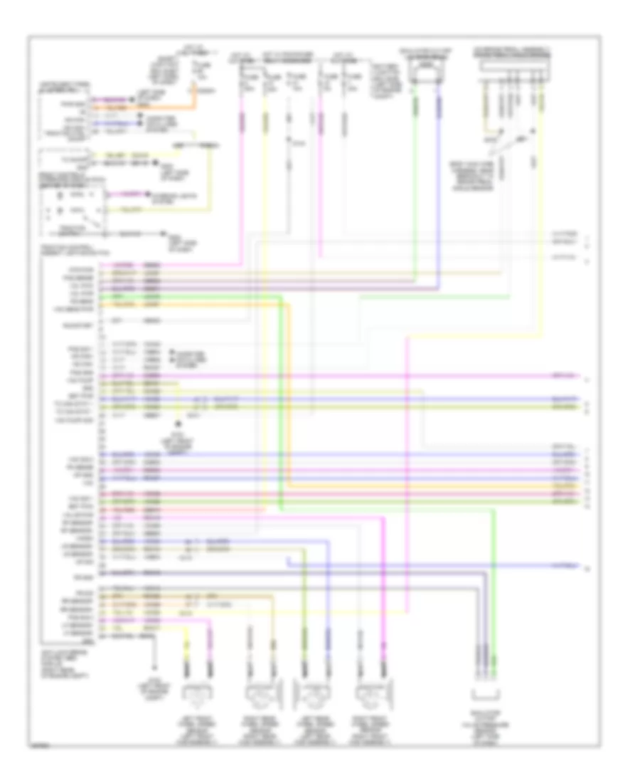
Anti-lock Brakes Wiring Diagram, Except Hybrid for Ford Fusion Sport 2012


List of elements for Anti-lock Brakes Wiring Diagram, Except Hybrid for Ford Fusion Sport 2012:
- (2.5l & 3.5l) (3.0l)
- (3.5l: dash panel to headlamp junction harness, near breakout to powertrain control module) s142
- 2.5l & 3.0l
- 2.5l/3.0l
- 20a
- 3.5l
- Anti-lock brake system (abs) module (right front of engine compt)
- Battery junction box (bjb) (left side of engine compt)
- Bpp
- Bpp input
- Bps
- Brake booster vacuum sensor (3.0l awd & 3.5l) (on brake booster)
- Brake pedal position switch (left side of dash)
- C139
- C144
- C175b
- C214
- C215
- C219
- C2280a
- C2280b
- C2280d
- C248
- C310b
- Cbp42
- Cca15
- Cca40
- Ccb08
- Ces09
- Computer data lines system
- Exterior lights system
- Front control interface module (fcim) (w/ navigation) (center of dash)
- Fuse 10a
- Fuse 15a
- Fuse 30a
- Fuse 40a
- Fusion
- G104 (2.5l & 3.0l: right front of engine compt) (3.5l: right side of engine compt)
- G202 (left side of dash)
- Gd116
- Gd123
- Gnd
- Hot at all times
- Hot in run or start
- Hot w/ pcm power relay energized
- Hs can +
- Hs can -
- Hs can+
- Hs can-
- Instrument panel cluster (ipc)
- Interior lights system
- Ivd pwr
- Ivd rtn
- Lca37
- Left front wheel speed sensor (left front hub assembly)
- Left rear wheel speed sensor (left rear hub assembly)
- Lf sensor+
- Lf sensor-
- Lr sensor+
- Lr sensor-
- Mkz
- Mtr gnd
- Mtr pwr
- Nca
- Powertrain control module (pcm) (left rear of engine compt)
- Pwr gnd
- Rca17
- Rca18
- Rca19
- Rca20
- Rca37
- Rca40
- Restraints control module (rcm) (under center console)
- Rf sensor+
- Rf sensor-
- Right front wheel speed sensor (right front hub assembly)
- Right rear wheel speed sensor (right rear hub assembly)
- Rr sensor+
- Rr sensor-
- Run/start
- S120
- S140
- Sas a
- Sas b
- Sbb08
- Sbb10
- Smart junction box (sjb) (left side of dash)
- Solid state
- Steering angle sensor module (sasm) (3.5l) (center of steering column)
- Switch traction
- Tc can stat +
- Tc can stat -
- Tc can stat+
- Tc can stat-
- Traction control/ambient lighting switch
- Traction ctl on/off
- Vac gnd
- Vac pwr
- Vac sig
- Valve pwr
- Vca03
- Vca04
- Vca05
- Vca06
- Vca23
- Vca24
- Vca38
- Vca41
- Vca42
- Vdb04
- Vdb05
- Vdbo4
- Vdbo5
Anti-lock Brakes Wiring Diagram, Hybrid (1 of 2) for Ford Fusion Sport 2012
List of elements for Anti-lock Brakes Wiring Diagram, Hybrid (1 of 2) for Ford Fusion Sport 2012:
- (body main wire harness, near breakout to brake pedal angle sensor)
- (left side of dash) g202
- (on brake pedal assembly) brake pedal angle sensor
- Anti-lock brake system (abs) module (right rear of engine compt)
- Battery junction box (bjb) (left side of engine compt)
- Bst pwm
- Bst pwr
- C219
- C2280a
- Cbb30
- Cbb31
- Cbb32
- Cbb37
- Cbk03
- Cca15
- Cca22
- Ccb30
- Ccb33
- Computer data lines system
- Front controls interface module (fcim) (center of dash)
- Fuse 10a
- Fuse 30a
- Fuse 50a
- Fuse 5a
- Fusion
- G103 (left front of engine compt)
- G202 (left side of dash)
- Gd116
- Gd121
- Gnd
- Hot at all times
- Hot w/ pcm power relay energized
- Hs can+
- Hs can+ traction ctrl on/off
- Hs can-
- Instrument panel cluster (ipc)
- Interior lights system
- Lca16
- Lca27
- Lca37
- Left front wheel speed sensor (left front hub assembly)
- Left rear wheel speed sensor (left rear hub assembly)
- Lf sensor+
- Lf sensor-
- Lr sensor+
- Lr sensor-
- Mkz
- Mp gnd
- Mp sig
- Mtr pwr
- Nca
- Pas gnd
- Pas sense
- Pas sig 1
- Pas sig 2
- Pm sense
- Ps gnd
- Ps sens
- Ps sig
- Pwr gnd
- Rca16
- Rca17
- Rca18
- Rca19
- Rca20
- Rca27
- Rca37
- Rcb33
- Rf sensor+
- Rf sensor-
- Right front wheel speed sensor (right front hub assembly)
- Right rear wheel speed sensor (right rear hub assembly)
- Rr sensor+
- Rr sensor-
- Run/start
- S144
- S270
- S271
- Sbb08
- Sbb10
- Simulator cut-off valve pressure sensor (left side of dash)
- Simulator cut-off valve solenoid
- Smart junction box (sjb) (left side of dash)
- Tc can stat +
- Tc can stat -
- Tc on/off
- Traction control/ ambient lighting switch
- Traction switch
- Vac
- Vac pump
- Vac pump mon
- Vac sens pwr
- Vac sig 1
- Vac sig 2
- Vacrc
- Valve pwr
- Vca03
- Vca04
- Vca05
- Vca06
- Vca13
- Vca22
- Vca23
- Vca24
- Vca30
- Vca38
- Vca39
- Vca43
- Vcb34
- Vdb04
- Vdb05
- Vol pwm
- Vol pwr
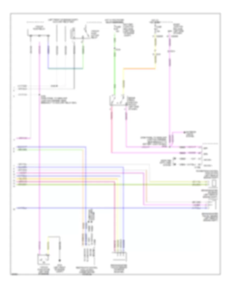
Anti-lock Brakes Wiring Diagram, Hybrid (2 of 2) for Ford Fusion Sport 2012
List of elements for Anti-lock Brakes Wiring Diagram, Hybrid (2 of 2) for Ford Fusion Sport 2012:
- (dash panel to headlamp junction harness, near breakout to battery junction box) s142
- (left front of engine compt) auxiliary relay box
- Battery junction box (bjb) (left side of engine compt)
- Bpp
- Bps
- Brake booster solenoid (left rear of engine compt)
- Brake booster travel sensor (left rear of engine compt)
- Brake booster vacuum sensor (on brake booster)
- Brake pedal position switch (left side of dash)
- C175b
- C214
- C219
- C2280b
- C2280d
- C310b
- Ceb08
- Ces09
- Computer data lines system
- Exterior lights system
- Fuse 15a
- G103 (left front of engine compt)
- Hot at all times
- Hot w/ pcm power relay energized
- Hs can +
- Hs can -
- Powertrain control module (pcm) (left rear of engine compt)
- Restraints control module (rcm) (under center console)
- S140
- S190
- S192 (dash panel to headlamp junction harness, near breakout to auxiliary relay box)
- Smart junction box (sjb) (left side of dash)
- System data lines computer
- Tc can stat+
- Tc can stat-
- Vacuum pump cut-off relay
- Vacuum pump motor (left side of engine)
- Vacuum pump relay
- Vca23
- Vca24
- Vdb04
- Vdb05

 Čeština
 Dansk
Dansk Deutsch
 Ελληνικά
 English
 English
 Español
 Suomi
Suomi Français
 Français
 עברית
עברית Hrvatski
 Magyar
 Italiano
 日本語
日本語 한국어
한국어 Nederlands
 Polski
 Português
 Português
 Română
 Русский
 Slovenčina
 Slovenščina
 Svenska
 Türkçe