ENGINE PERFORMANCE
5.4L
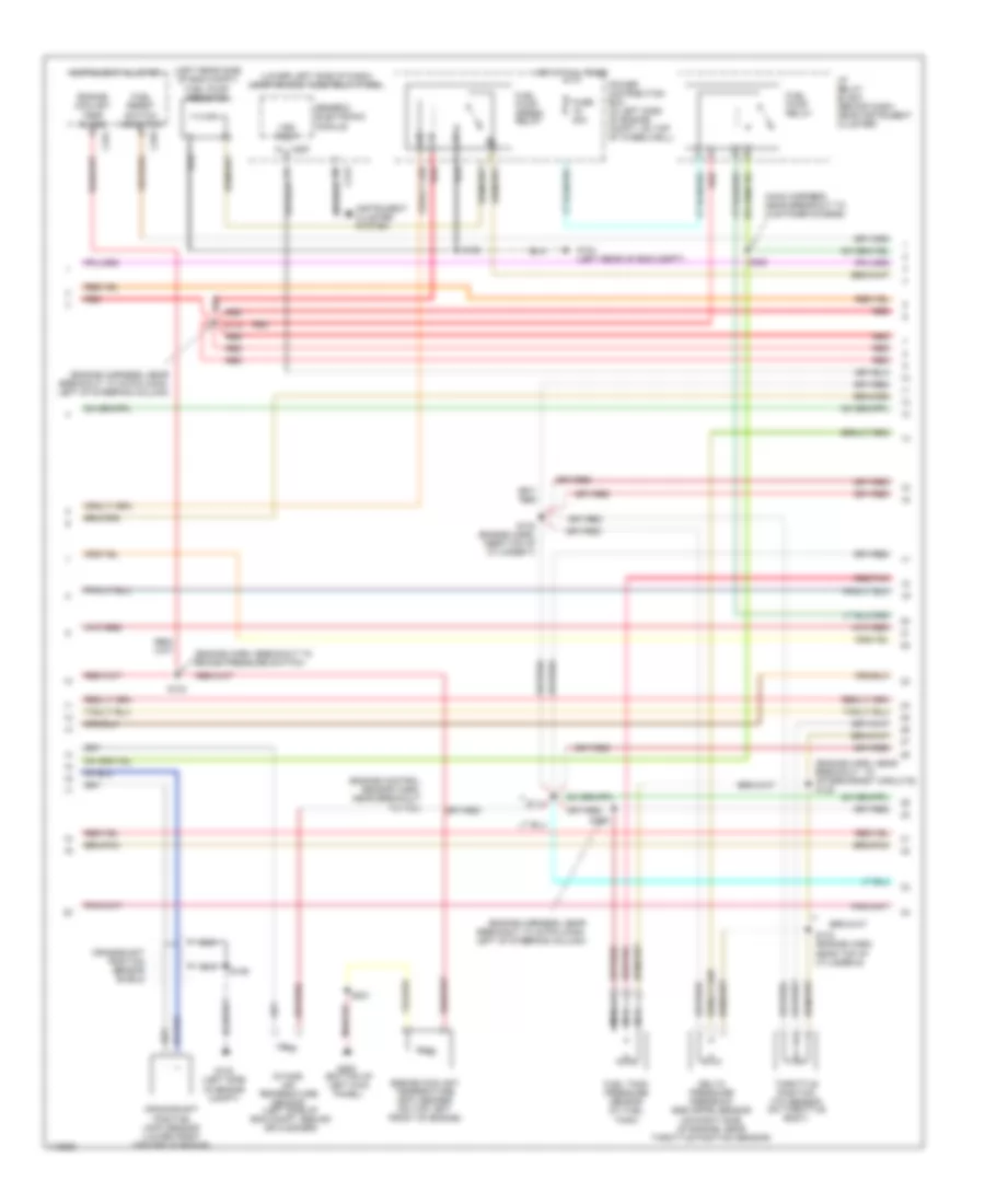
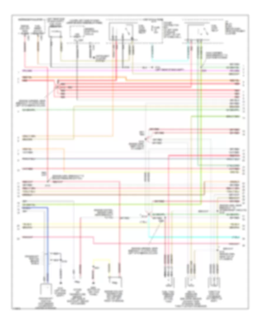
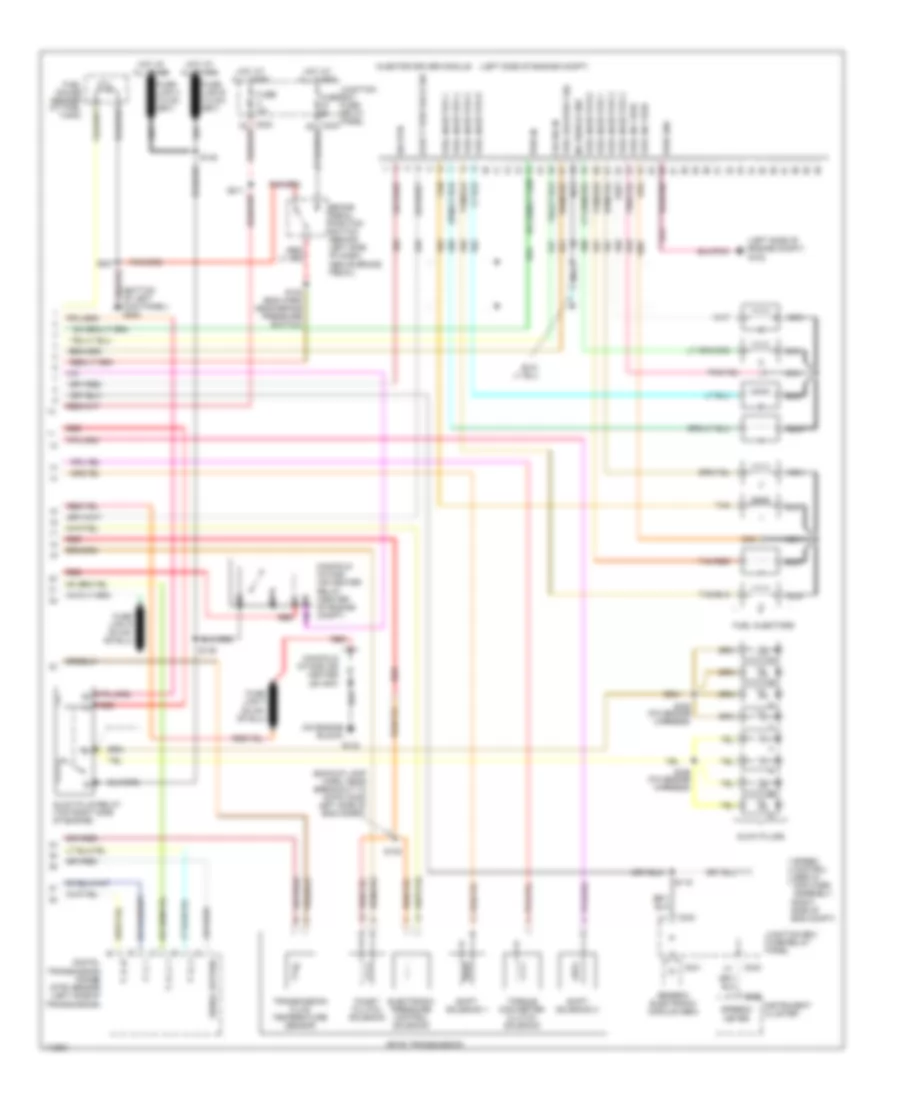
5.4L, Engine Performance Wiring Diagram (1 of 4) for Ford Cab & Chassis F350 Super Duty 1999
 https://portal-diagnostov.com/license.html
Automotive Electricians Portal FZCO
Automotive Electricians Portal FZCO
https://portal-diagnostov.com/license.html
https://portal-diagnostov.com/license.html
Automotive Electricians Portal FZCO
Automotive Electricians Portal FZCO
List of elements for 5.4L, Engine Performance Wiring Diagram (1 of 4) for Ford Cab & Chassis F350 Super Duty 1999:
- (bottom of left kick panel) g200
- (eng sens harn, right side of eng, above cylinder 3)
- (engine harness, near breakout to power distribution box)
- (left rear corner of eng compt) g104
- (left rear corner of engine compt) g104
- (not used)
- (on left side of engine)
- (on right side of engine)
- 4x4 low ind sw
- 820 ohms
- Ac head press sw
- Air conditioning system
- Body computer system
- C243
- C251
- C253
- Ccs
- Ckp(+)
- Ckp(-)
- Data link (+)
- Data link (-)
- Data link connector (dlc) (partial) (behind center of dash)
- Data output
- Diag grd
- Digital transmission range (dtr) sensor (on left side of transmission)
- Egr sol
- Fpsr cntrl
- Fuel gauge in
- Fuel pump mon
- Fuse 10a
- Fuse 20a
- Fuse 30a
- Hego 12
- Hot at all times
- Hot in run or start
- Iat
- Ign coil 1
- Ign coil 3
- Ign coil 5
- Ign coil 6
- Ignition coils
- Instrument cluster
- Instrument cluster system
- Intake manifold
- Intake manifold tunning valve (on top left side of engine)
- Junction box fuse/relay panel (behind lower left side of dash)
- Maf
- Mil ind
- Nca
- Not used
- O/d off
- Overdrive cancel switch (a/t)
- Pcm power diode
- Pcm power relay
- Power distribution box (in left side of engine compt, on top wheelwell)
- Powertrain control module (pcm) (on left side of firewall)
- Pwr gnd
- R n
- Radio noise capacitor
- Radio noise capacitor 2
- Red
- Reprog pwr
- S102
- S103
- S106
- S120
- S130 (engine harn, near breakout to throttle body conn)
- S135
- S201
- S213
- Shift sol 1
- Shift sol 2
- Tach
- Tcs
- Temp output
- Tft
- To dtr sensor (diagram 4 of 4)
- Tr1
- Tr2
- Tr4
- Trans ctrl ind
- Transmission control indicator lamp
- Vss (-)
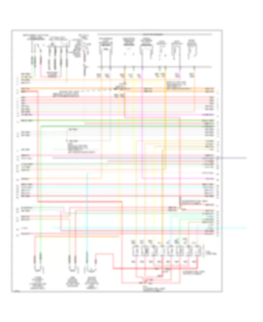
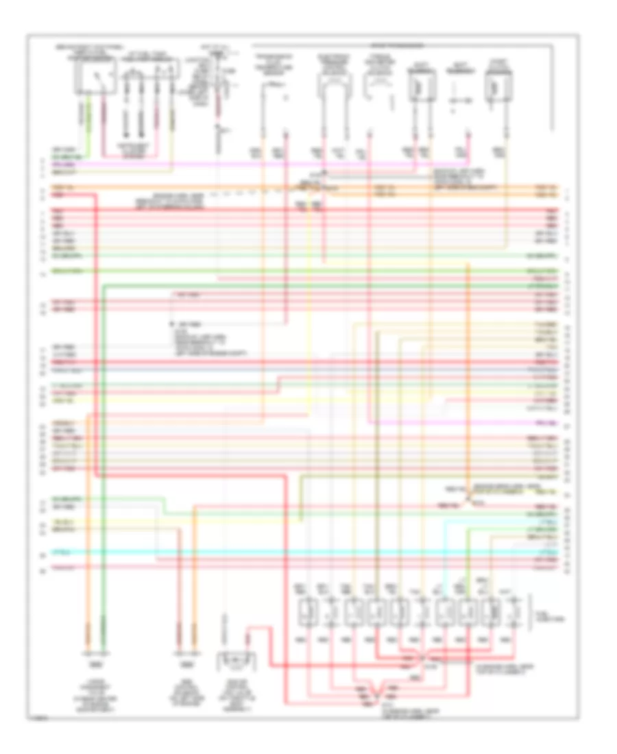
5.4L, Engine Performance Wiring Diagram (2 of 4) for Ford Cab & Chassis F350 Super Duty 1999
 https://portal-diagnostov.com/license.html
Automotive Electricians Portal FZCO
Automotive Electricians Portal FZCO
https://portal-diagnostov.com/license.html
https://portal-diagnostov.com/license.html
Automotive Electricians Portal FZCO
Automotive Electricians Portal FZCOList of elements for 5.4L, Engine Performance Wiring Diagram (2 of 4) for Ford Cab & Chassis F350 Super Duty 1999:
- (engine control sensor harn, near breakout to pcm)
- (engine harn, breakout to brake pressure switch)
- (engine harn, near breakout to aftermarket circuits) s128
- (engine harness, near breakout to 40-pin conn, left of steering column)
- (left rear side of eng compt) fuel pump resistor
- (lower left side of dash) junction box fuse/relay panel
- (main harness, near breakout to customer access)
- C251
- C253
- C267
- Crankshaft position (ckp) sensor (lower front center of engine)
- Crankshaft position sensor shield
- Delta pressure feedback egr (dpfe) sensor (on right side of engine, near throttle position sensor)
- Engine coolant temp guage
- Engine coolant temperature (ect) sender (on top left front of engine)
- Fuel pump relay
- Fuel pump speed relay
- Fuel reset switch indicator
- Fuel tank pressure sensor (at fuel tank)
- Fuse 20a
- G102 (left side of engine compt)
- G104 (left rear of eng compt)
- G200 (bottom of left kick panel)
- Generic electronic module
- Hot at all times
- I/p relay block (behind dash, near instrument cluster)
- Instrument cluster
- Instrument cluster system
- Intake air temperature sensor (left side of eng compt, behind air cleaner)
- Nca
- Power distribution box (in left side of engine compt, on top of wheelwell)
- Red
- Red/pnk
- S102
- S104
- S106
- S114
- S123
- S129
- S132 (engine harn, near top of cylinder 7)
- S133 (engine harn, near top of cylinder 6)
- S201
- S226
- Throttle position (tp) sensor (on throttle body)
- Vss input
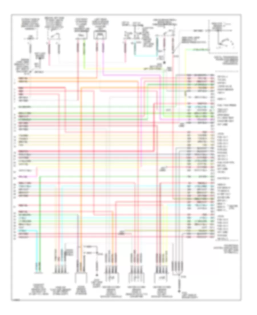
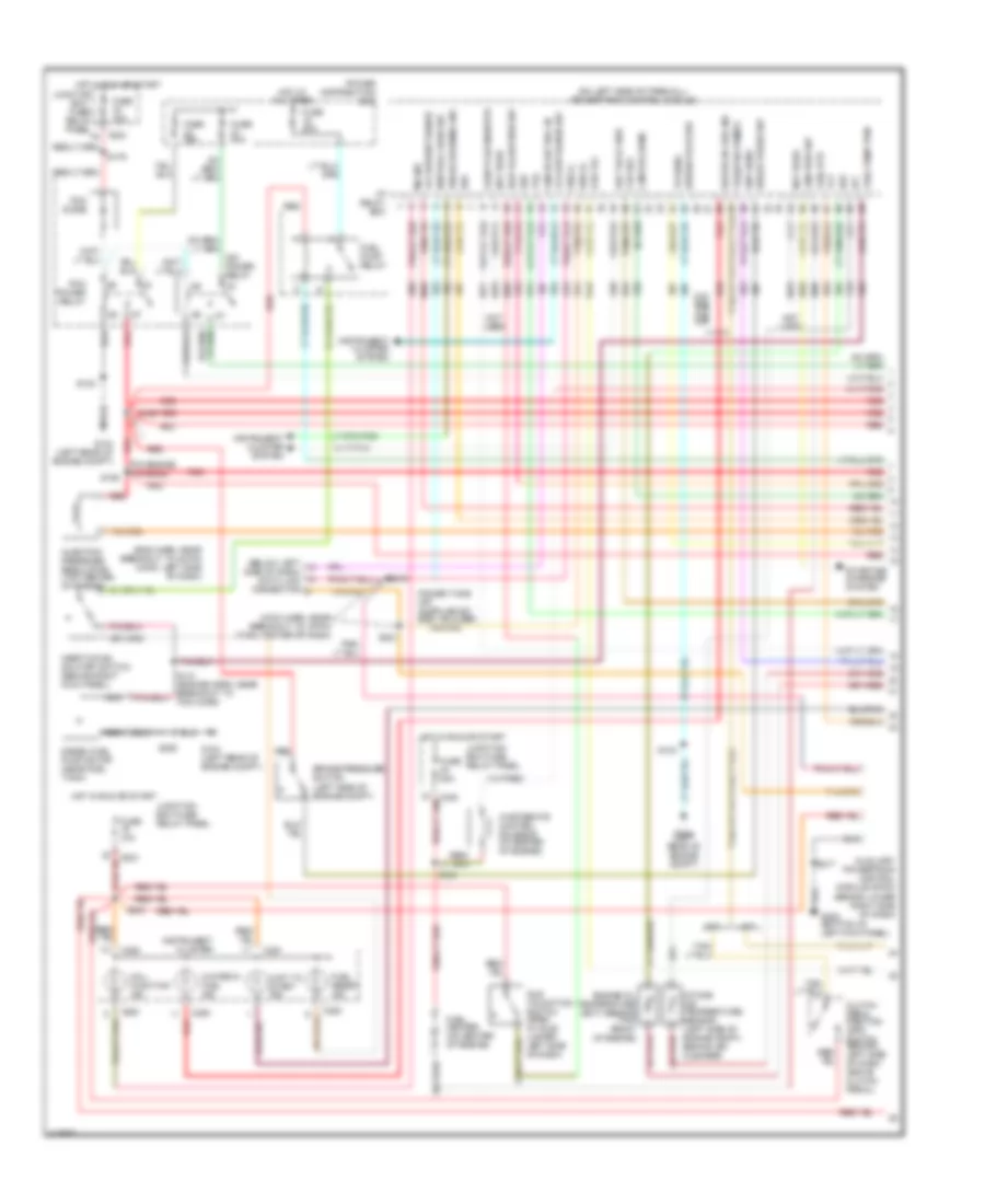
5.4L, Engine Performance Wiring Diagram (3 of 4) for Ford Cab & Chassis F350 Super Duty 1999
 https://portal-diagnostov.com/license.html
Automotive Electricians Portal FZCO
Automotive Electricians Portal FZCO
https://portal-diagnostov.com/license.html
https://portal-diagnostov.com/license.html
Automotive Electricians Portal FZCO
Automotive Electricians Portal FZCOList of elements for 5.4L, Engine Performance Wiring Diagram (3 of 4) for Ford Cab & Chassis F350 Super Duty 1999:
- (at fuel tank) fuel pump module
- (backup lamp harn, near breakout to 16-pin conn, in left side of eng compt)
- (behind right kick panel) inertia fuel shut-off switch
- (engine harn, near breakout to 40-pin conn, left of steering column)
- (engine sens harn, near top of cylinder 8)
- (in engine harn, near top of cylinder 3)
- (in rear center of engine compartment)
- 4r100 transmission
- Coast clutch solenoid
- Egr control solenoid (on left side of engine)
- Electronic pressure control solenoid
- Fuel injectors
- Fuse 5a
- Hot at all times
- Idle air control (iac) valve (on throttle body assembly)
- Instrument cluster system
- Junction box fuse/ relay panel (behind lower left side of dash)
- Nca
- Red
- Red/pnk
- S122
- S131 (in engine harn, near top of cylinder 7)
- S134
- S136
- S138
- S139 (backup lamp harn, near breakout to 16-pin conn, in left side of engine compt)
- Shift solenoid 1
- Shift solenoid 2
- Tan
- Tan/ red
- Tan/red
- Torque converter clutch solenoid
- Transmission fluid temperature sensor
- Vapor managment valve
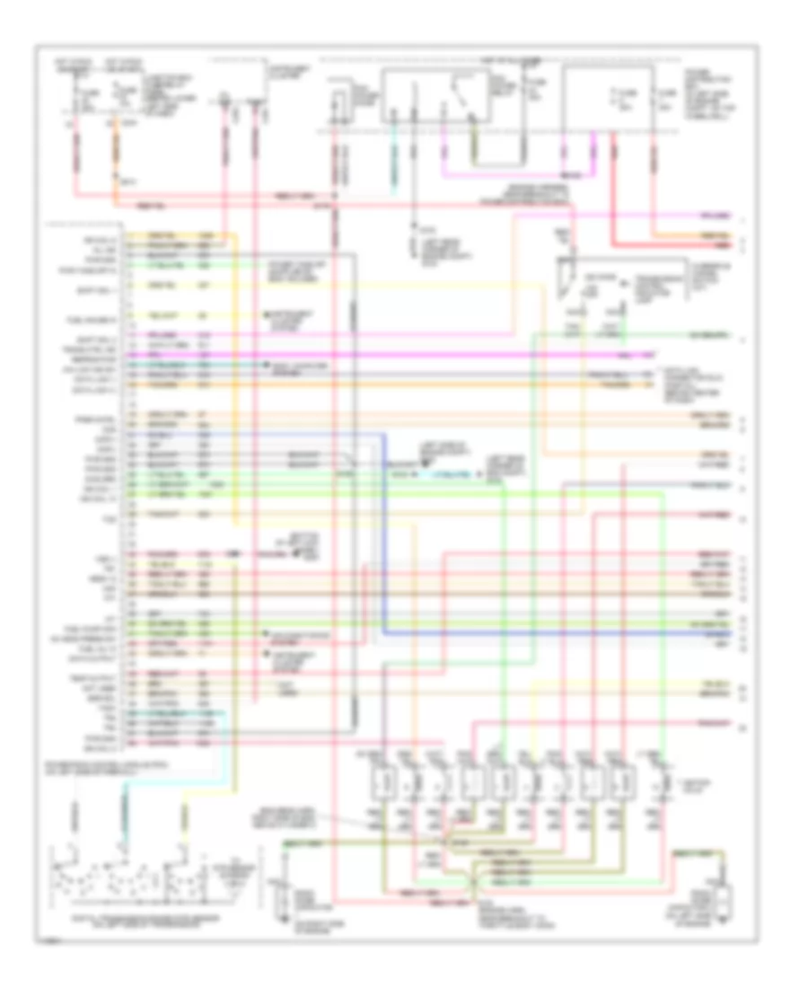
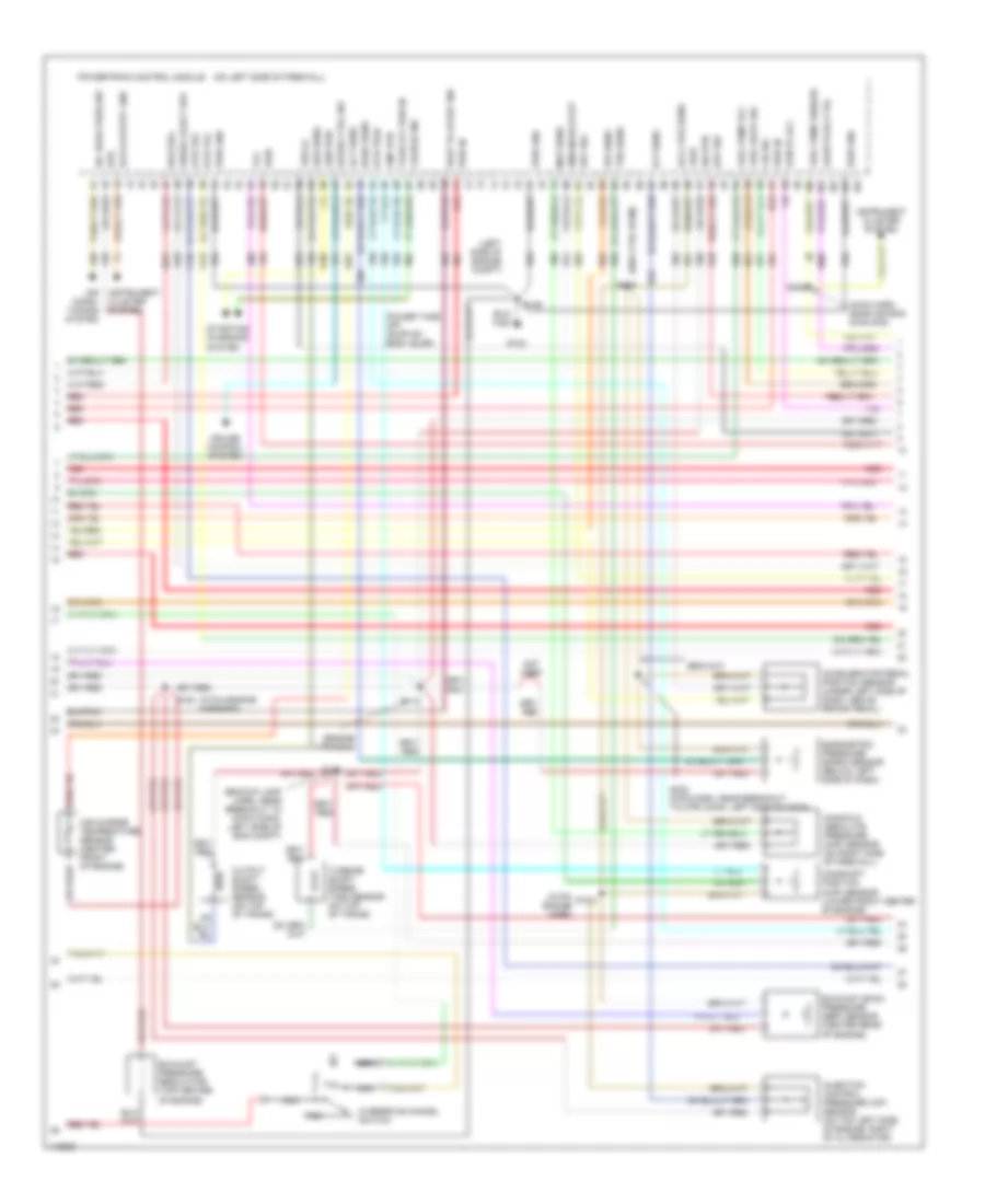
5.4L, Engine Performance Wiring Diagram (4 of 4) for Ford Cab & Chassis F350 Super Duty 1999
 https://portal-diagnostov.com/license.html
Automotive Electricians Portal FZCO
Automotive Electricians Portal FZCO
https://portal-diagnostov.com/license.html
https://portal-diagnostov.com/license.html
Automotive Electricians Portal FZCO
Automotive Electricians Portal FZCOList of elements for 5.4L, Engine Performance Wiring Diagram (4 of 4) for Ford Cab & Chassis F350 Super Duty 1999:
- (a/t)
- (above brake pedal) brake pedal position (bpp) switch
- (behind left side of dash, above clutch pedal) clutch pedal position switch (m/t)
- (eng harn, near breakout to brake press switch)
- (engine harn, near breakout to 16-pin conn, left side of eng compt) s115
- (in right side of engine compt) speed control servo/amplifier assembly
- (left rear side of engine compartment) canister vent solenoid
- (m/t)
- (not used)
- (top front of engine) cylinder head temperature (cht) sensor
- 5v ref volt
- Anti-lock brakes system
- Bpp sw
- Cam pos in
- Camshaft position sensor (cmp) (on front of of left cyl head)
- Canister vent
- Cyl head temp
- Digital transmission range (dtr) sensor (left side of transmission)
- Dpfe sens
- Epc sol
- From dtr sensor (diagram 1 of 4)
- Fuel inj 1
- Fuel inj 2
- Fuel inj 3
- Fuel inj 4
- Fuel inj 5
- Fuel inj 6
- Fuel inj 7
- Fuel inj 8
- Fuel pump ctrl
- Fuel tank press
- Fuse 15a
- Fuse 5a
- G102 (left side of eng compt)
- G102 (left side of engine compt)
- G200 (bottom of left kick panel)
- Heated oxygen sensor (ho2s) 11 (on right exhaust manifold)
- Heated oxygen sensor (ho2s) 12 (rear of catalytic converter)
- Heated oxygen sensor (ho2s) 21 (on left exhaust manifold)
- Heater ctrl
- Hego 11
- Hego 12
- Hego 21
- Hot at all times
- Hot in start
- Iac sol
- Ign coil 2
- Ign coil 4
- Ign coil 7
- Ign coil 8
- Junction box fuse/ relay panel (behind lower left side of dash)
- Kap b(+)
- Knock sensor
- Knock sensor (on rear of engine)
- Knock sensor shield
- Maf sens in
- Mass air flow (maf) sensor (in left front of eng compt)
- Nca
- Not used
- Powertrain control module (pcm) (on left side of firewall)
- Pwr gnd
- Red
- Red/pnk
- S106
- S108
- S201
- Sig return
- Tan
- Tan/red
- Tcc sol
- Tp sens in
- Tr3a (a/t) cpp (m/t)
- Vapor valve
- Vpwr
- Vss (+)
- Vss input
6.8L
6.8L, Engine Performance Wiring Diagram (1 of 4) for Ford Cab & Chassis F350 Super Duty 1999
 https://portal-diagnostov.com/license.html
Automotive Electricians Portal FZCO
Automotive Electricians Portal FZCO
https://portal-diagnostov.com/license.html
https://portal-diagnostov.com/license.html
Automotive Electricians Portal FZCO
Automotive Electricians Portal FZCOList of elements for 6.8L, Engine Performance Wiring Diagram (1 of 4) for Ford Cab & Chassis F350 Super Duty 1999:
- (bottom of left kick panel) g200
- (eng sens harn, right side of eng, above cylinder 3)
- (engine harness, near breakout to power distribution box)
- (left rear corner of eng compt) g104
- (left rear corner of engine compt) g104
- (not used)
- (on left side of engine)
- (on right side of engine)
- 4x4 low ind sw
- 820 ohms
- Ac head press sw
- Air conditioning system
- Body computer system
- C243
- C251
- C253
- Ccs
- Ckp(+)
- Ckp(-)
- Data link (+)
- Data link (-)
- Data link connector (dlc) (partial) (behind center of dash)
- Data output
- Diag grd
- Digital transmission range (dtr) sensor (on left side of transmission)
- Egr sol
- Fpsr cntrl
- Fuel gauge in
- Fuel inj 10
- Fuel pump mon
- Fuse 10a
- Fuse 20a
- Fuse 30a
- Hego 12
- Hot at all times
- Hot in run or start
- Iat
- Ign coil 1
- Ign coil 10
- Ign coil 5
- Ign coil 6
- Ignition coils
- Instrument cluster
- Instrument cluster system
- Junction box fuse/relay panel (behind lower left side of dash)
- Maf
- Mil ind
- Nca
- Not used
- O/d off
- Overdrive cancel switch (a/t)
- Pcm power diode
- Pcm power relay
- Power distribution box (in left side of engine compt, on top wheelwell)
- Powertrain control module (pcm) (on left side of firewall)
- Pwr gnd
- Pwr take off in
- R n
- Radio noise capacitor
- Radio noise capacitor 2
- Red
- Red/
- Reprog pwr
- S102
- S103
- S106
- S120
- S130 (engine harn, near breakout to throttle body conn)
- S135
- S201
- S213
- Shift sol 1
- Shift sol 2
- Tach
- Tcs
- Temp output
- Tft
- To dtr sensor (diagram 4 of 4)
- Tr1
- Tr2
- Tr4
- Trans ctrl ind
- Transmission control indicator lamp
- Vss (-)
6.8L, Engine Performance Wiring Diagram (2 of 4) for Ford Cab & Chassis F350 Super Duty 1999
 https://portal-diagnostov.com/license.html
Automotive Electricians Portal FZCO
Automotive Electricians Portal FZCO
https://portal-diagnostov.com/license.html
https://portal-diagnostov.com/license.html
Automotive Electricians Portal FZCO
Automotive Electricians Portal FZCOList of elements for 6.8L, Engine Performance Wiring Diagram (2 of 4) for Ford Cab & Chassis F350 Super Duty 1999:
- (engine control sensor harn, near breakout to pcm)
- (engine harn, breakout to brake pressure switch)
- (engine harn, near breakout to aftermarket circuits) s128
- (engine harness, near breakout to 40-pin conn, left of steering column)
- (left rear side of eng compt) fuel pump resistor
- (lower left side of dash) junction box fuse/relay panel
- (main harness, near breakout to customer access)
- C251
- C253
- C267
- Crankshaft position (ckp) sensor (lower front center of engine)
- Crankshaft position sensor shield
- Delta pressure feedback egr (dpfe) sensor (on right side of engine, near throttle position sensor)
- Engine coolant temp guage
- Engine coolant temperature (ect) sender (on top left front of engine)
- Fuel pump relay
- Fuel pump speed relay
- Fuel reset switch indicator
- Fuel tank pressure sensor (at fuel tank)
- Fuse 20a
- G102 (left side of engine compt)
- G104 (left rear of eng compt)
- G200 (bottom of left kick panel)
- Generic electronic module
- Hot at all times
- I/p relay block (behind dash, near instrument cluster)
- Instrument cluster
- Instrument cluster system
- Intake air temperature sensor (left side of eng compt, behind air cleaner)
- Nca
- Power distribution box (in left side of engine compt, on top of wheelwell)
- Red
- Red/pnk
- S102
- S104
- S106
- S114
- S123
- S129
- S132 (engine harn, near top of cylinder 7)
- S133 (engine harn, near top of cylinder 6)
- S201
- S226
- Throttle position (tp) sensor (on throttle body)
- Vss input
6.8L, Engine Performance Wiring Diagram (3 of 4) for Ford Cab & Chassis F350 Super Duty 1999
 https://portal-diagnostov.com/license.html
Automotive Electricians Portal FZCO
Automotive Electricians Portal FZCO
https://portal-diagnostov.com/license.html
https://portal-diagnostov.com/license.html
Automotive Electricians Portal FZCO
Automotive Electricians Portal FZCOList of elements for 6.8L, Engine Performance Wiring Diagram (3 of 4) for Ford Cab & Chassis F350 Super Duty 1999:
- (at fuel tank) fuel pump module
- (backup lamp harn, near breakout to 16-pin conn, in left side of eng compt)
- (behind right kick panel) inertia fuel shut-off switch
- (engine harn, near breakout to 40-pin conn, left of steering column)
- (engine sens harn, near top of cylinder 8)
- (in engine harn, near top of cylinder 3)
- (in rear center of engine compartment)
- 4r100 transmission
- Coast clutch solenoid
- Egr control solenoid (on left side of engine)
- Electronic pressure control solenoid
- Fuel injectors
- Fuse 5a
- Hot at all times
- Idle air control (iac) valve (on throttle body assembly)
- Instrument cluster system
- Junction box fuse/ relay panel (behind lower left side of dash)
- Nca
- Red
- Red/pnk
- S122
- S131 (in engine harn, near top of cylinder 7)
- S134
- S136
- S138
- S139 (backup lamp harn, near breakout to 16-pin conn, in left side of engine compt)
- Shift solenoid 1
- Shift solenoid 2
- Tan
- Tan/ red
- Tan/red
- Torque converter clutch solenoid
- Transmission fluid temperature sensor
- Vapor managment valve
6.8L, Engine Performance Wiring Diagram (4 of 4) for Ford Cab & Chassis F350 Super Duty 1999
 https://portal-diagnostov.com/license.html
Automotive Electricians Portal FZCO
Automotive Electricians Portal FZCO
https://portal-diagnostov.com/license.html
https://portal-diagnostov.com/license.html
Automotive Electricians Portal FZCO
Automotive Electricians Portal FZCOList of elements for 6.8L, Engine Performance Wiring Diagram (4 of 4) for Ford Cab & Chassis F350 Super Duty 1999:
- (a/t)
- (above brake pedal) brake pedal position (bpp) switch
- (behind left side of dash, above clutch pedal) clutch pedal position switch (m/t)
- (eng harn, near breakout to brake press switch)
- (engine harn, near breakout to 16-pin conn, left side of eng compt) s115
- (in right side of engine compt) speed control servo/amplifier assembly
- (left rear side of engine compartment) canister vent solenoid
- (m/t)
- (top front of engine) cylinder head temperature (cht) sensor
- 5v ref volt
- Anti-lock brakes system
- Bpp sw
- Cam pos in
- Camshaft position sensor (cmp) (on front of of left cyl head)
- Canister vent
- Cyl head temp
- Digital transmission range (dtr) sensor (left side of transmission)
- Dpfe sens
- Epc sol
- From dtr sensor (diagram 1 of 4)
- Fuel inj 1
- Fuel inj 2
- Fuel inj 3
- Fuel inj 4
- Fuel inj 5
- Fuel inj 6
- Fuel inj 7
- Fuel inj 8
- Fuel inj 9
- Fuel pump ctrl
- Fuel tank press
- Fuse 15a
- Fuse 5a
- G102 (left side of eng compt)
- G102 (left side of engine compt)
- G200 (bottom of left kick panel)
- Heated oxygen sensor (ho2s) 11 (on right exhaust manifold)
- Heated oxygen sensor (ho2s) 12 (rear of catalytic converter)
- Heated oxygen sensor (ho2s) 21 (on left exhaust manifold)
- Heater ctrl
- Hego 11
- Hego 12
- Hego 21
- Hot at all times
- Hot in start
- Iac sol
- Ign coil 2
- Ign coil 3
- Ign coil 4
- Ign coil 7
- Ign coil 8
- Ign coil 9
- Junction box fuse/ relay panel (behind lower left side of dash)
- Kap b(+)
- Knock sensor
- Knock sensor (on rear of engine)
- Knock sensor shield
- Maf sens in
- Mass air flow (maf) sensor (in left front of eng compt)
- Nca
- Powertrain control module (pcm) (on left side of firewall)
- Pwr gnd
- Red
- Red/pnk
- S106
- S108
- S201
- Sig return
- Tan
- Tan/red
- Tcc sol
- Tp sens in
- Tr3a (a/t) cpp (m/t)
- Vapor valve
- Vpwr
- Vss (+)
- Vss input
7.3L DI TURBO DIESEL
7.3L DI Turbo Diesel, Engine Performance Wiring Diagram (1 of 3) for Ford Cab & Chassis F350 Super Duty 1999
 https://portal-diagnostov.com/license.html
Automotive Electricians Portal FZCO
Automotive Electricians Portal FZCO
https://portal-diagnostov.com/license.html
https://portal-diagnostov.com/license.html
Automotive Electricians Portal FZCO
Automotive Electricians Portal FZCOList of elements for 7.3L DI Turbo Diesel, Engine Performance Wiring Diagram (1 of 3) for Ford Cab & Chassis F350 Super Duty 1999:
- (behind lower right side of dash)
- (below left side of dash) data link connector
- (eng harn, near breakout to 40-pin conn, left side of dash)
- (left side of engine compt)
- (main harn, near breakout to 16-pin conn, center of dash)
- (on left side of firewall) powertrain control module
- (pia engine harness)
- 224 (a/t) 306 (m/t)
- 4x4 low range sw
- A/t
- Aux tach feed
- Auxiliary powertrain control module (apcm)
- Brake press sw
- Brake pressure switch
- Brake warning ind
- Bus (+)
- Bus (-)
- C243
- C250
- C251
- C253
- Cam pos sens
- Ccs sol
- Clutch pedal position (cpp) switch (behind left side of dash, above clutch pedal)
- Diesel fuel pump motor (near fuel tank)
- Dtr-tr1
- Ebp sens
- Engine oil temperature (eot) sensor (top front of engine)
- Eot
- Fuel heater (on center of engine)
- Fuel htr
- Fuel pump pwr
- Fuel pump relay
- Fuel reset ind
- Fuse 10a
- Fuse 20a
- Fuse 30a
- G104 (left rear of engine compt)
- G200 (bottom of left kick panel)
- Gen pwr sw
- Gen scan tool in
- Glow plug monitor
- Hot at all times
- Hot in run or start
- I/p relay box
- Iat
- Idle validation sw
- Idle validation switch (open at idle) (lower left side of dash)
- Idm power relay
- Inertia fuel shutoff switch (behind right kick panel)
- Injection pressure regulator (top center of engine)
- Instrument cluster
- Instrument cluster system
- Intake air temperature sensor (left side of engine compt, behind air cleaner)
- Junction box fuse/ relay panel
- Lo current sense
- M/t
- Mal- function ind
- Mil ind
- Nca
- Neutral gear sw
- Not used
- Pcm diode
- Pcm power relay
- Power distribution box
- Red
- Red s123
- S102
- S103
- S141 (engine harn, near breakout to pcm conn)
- S154
- S158
- S179
- S213
- S217
- S219
- S221
- S250
- Speed/tach grd
- Ss1
- Ss2
- Starting/ charging system
- Tcil
- Tcs(a/t)/cpp(m/t)
- Tft
- Tp sens
- Wait to start ind
- Wastegate control solenoid (in center of engine)
- Water in fuel ind
7.3L DI Turbo Diesel, Engine Performance Wiring Diagram (2 of 3) for Ford Cab & Chassis F350 Super Duty 1999
 https://portal-diagnostov.com/license.html
Automotive Electricians Portal FZCO
Automotive Electricians Portal FZCO
https://portal-diagnostov.com/license.html
https://portal-diagnostov.com/license.html
Automotive Electricians Portal FZCO
Automotive Electricians Portal FZCOList of elements for 7.3L DI Turbo Diesel, Engine Performance Wiring Diagram (2 of 3) for Ford Cab & Chassis F350 Super Duty 1999:
- (backup lamp harn, near breakout to 16-pin conn, left side of eng compt)
- (eng ctrl harn)
- (engine harness)
- (in pia engine harn)
- (in pia engine harness)
- (left side of engine compt)
- (main harn, near air bag diag mod)
- (on left side of firewall)
- A/c head pres sw
- Accelerator pedal position sensor (under left side of dash, above brake pedal)
- Accl pos sens
- Act sens
- Air charge temperature sensor (center front of engine)
- Air condi- tioning system
- Baro sens
- Barometric pressure (baro) sensor (below left side of dash)
- Bpp sw
- Camshaft position (cmp) sensor (lower front center of engine)
- Charge ind
- Cid sig
- Cmp rtn
- Cruise control system
- Data output link
- Diesel elect drv
- Dtr-tr2
- Dtr-tr3a
- Dtr-tr4
- Epc sol
- Epr
- Exhaust back pressure (ebp) sensor (center rear of engine)
- Exhaust pressure regulator (top center of engine)
- Fuel deliv sig
- Fuel pump rly
- Fuel pump sender
- G102
- Gen pwr
- Glow plug ctrl
- Icp sens
- Idm enable out
- Injection control pressure (icp) sensor (on top left side of engine, right of alternator)
- Instrument cluster system
- Ipr sens
- Manifold absolute pressure (map) sensor (on right side of firewall)
- Map sens
- Nca
- Not used
- Oss sens
- Output shaft speed sensor (on top of trans)
- Overdrive cancel switch
- Pcm to rly
- Power take off (supp by body bldr)
- Powertrain control module
- Pwr
- Pwr gnd
- Pwr in
- Red
- S106
- S114
- S128
- S139
- S151
- S153
- S208
- S222 (main harn, near breakout to 2-pin conn, left side of dash)
- Sig rtn
- Speed ctrl sw
- Starting/ charging system
- Take off pwr in
- Tcc
- Tcil
- Tcs
- Tss sens
- Turbine shaft speed (tss) sensor (on top of trans)
- Vref
- Vss (+)
- Wait to start ind
- Wcs sol
7.3L DI Turbo Diesel, Engine Performance Wiring Diagram (3 of 3) for Ford Cab & Chassis F350 Super Duty 1999
 https://portal-diagnostov.com/license.html
Automotive Electricians Portal FZCO
Automotive Electricians Portal FZCO
https://portal-diagnostov.com/license.html
https://portal-diagnostov.com/license.html
Automotive Electricians Portal FZCO
Automotive Electricians Portal FZCOList of elements for 7.3L DI Turbo Diesel, Engine Performance Wiring Diagram (3 of 3) for Ford Cab & Chassis F350 Super Duty 1999:
- (backup lamp harn, near breakout to 16-pin conn left side of eng compt)
- (bottom of left kick panel) g202
- (left side of engine compt)
- (left side of engine compt) g102
- (on engine block)
- (right side of eng compt)
- 4r100 transmission
- Brake pedal position switch (behind left side of dash, above brake pedal)
- C241
- C243
- C253
- Cid sig in
- Coast clutch solenoid
- Digital transmission range (dtr) sensor (left side of transmission)
- Elect feed back sig
- Electronic pressure control solenoid
- Fuel delivery sig
- Fuel gauge sender (at fuel tank)
- Fuel inj feed
- Fuel injector 1
- Fuel injector 2
- Fuel injector 3
- Fuel injector 4
- Fuel injector 5
- Fuel injector 6
- Fuel injector 7
- Fuel injector 8
- Fuel injectors
- Fuse 5a
- G132
- Generic electronic module (gem)
- Glow plug relay (top right side of engine)
- Glow plugs
- Hot at all times
- Inj shield gnd
- Injector driver module
- Instrument cluster
- Junction box fuse/ relay panel
- Junction box fuse/relay panel
- Manifold intake air heater (58 amp)
- Manifold intake air heater relay (center of engine compt)
- Nca
- P, 2, 1
- P, r, 2
- P, r, 2, 1
- P, r, n
- Pwr gnd
- Pwr in
- Red
- S108 (eng harn near brake pressure switch)
- S115
- S138
- S148
- S149
- S155 (pia engine harness)
- S156 (pia engine harness)
- S211
- Shift solenoid 1
- Shift solenoid 2
- Sig rtn
- Signal return
- Speed control servo/ amplifier assembly
- Speedo- meter
- Tan
- Tan/red
- Torque converter clutch solenoid
- Transmission fluid temperature sensor

 Čeština
 Dansk
Dansk Deutsch
 Ελληνικά
 English
 English
 Español
 Suomi
Suomi Français
 Français
 עברית
עברית Hrvatski
 Magyar
 Italiano
 日本語
日本語 한국어
한국어 Nederlands
 Polski
 Português
 Português
 Română
 Русский
 Slovenčina
 Slovenščina
 Svenska
 Türkçe
