ENGINE PERFORMANCE
5.4L
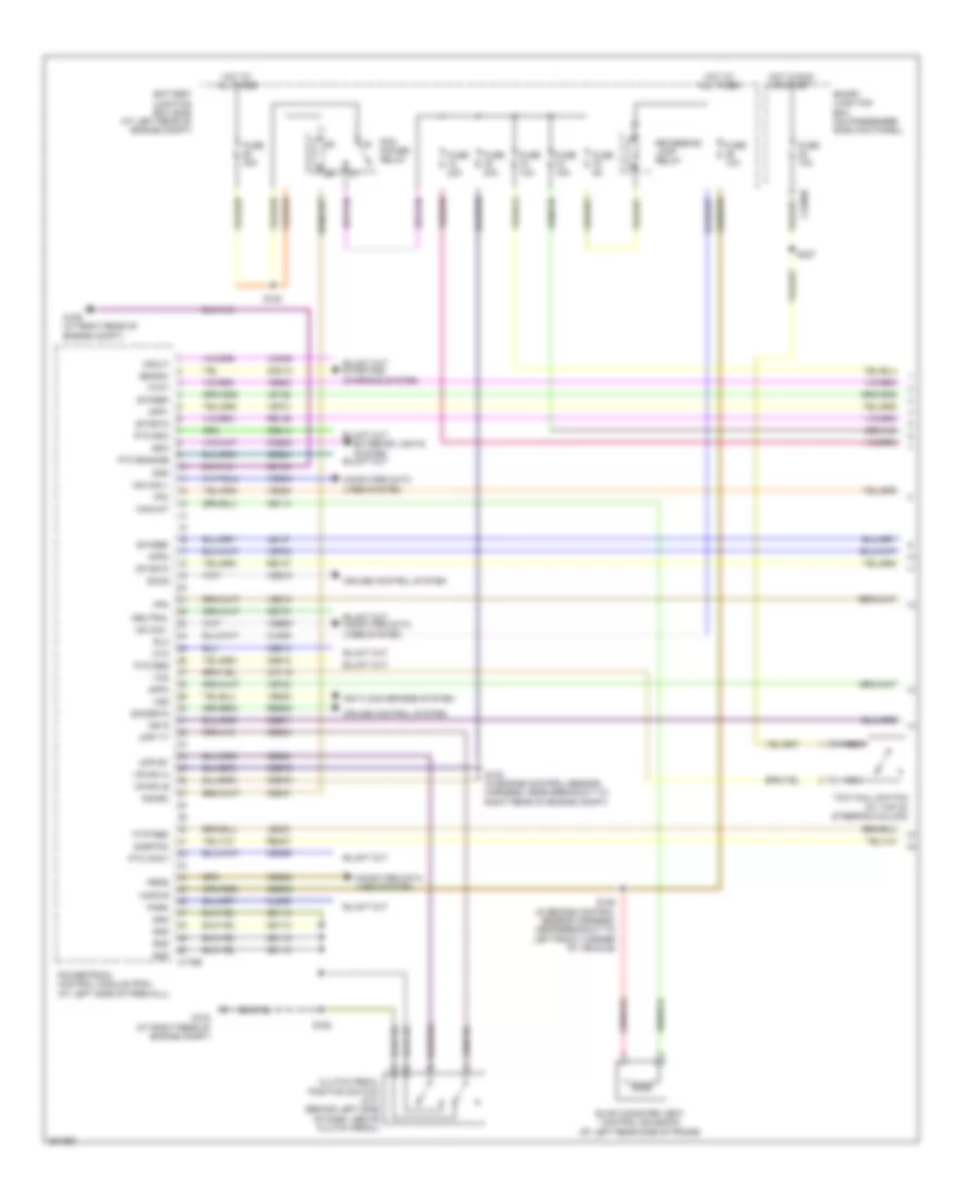
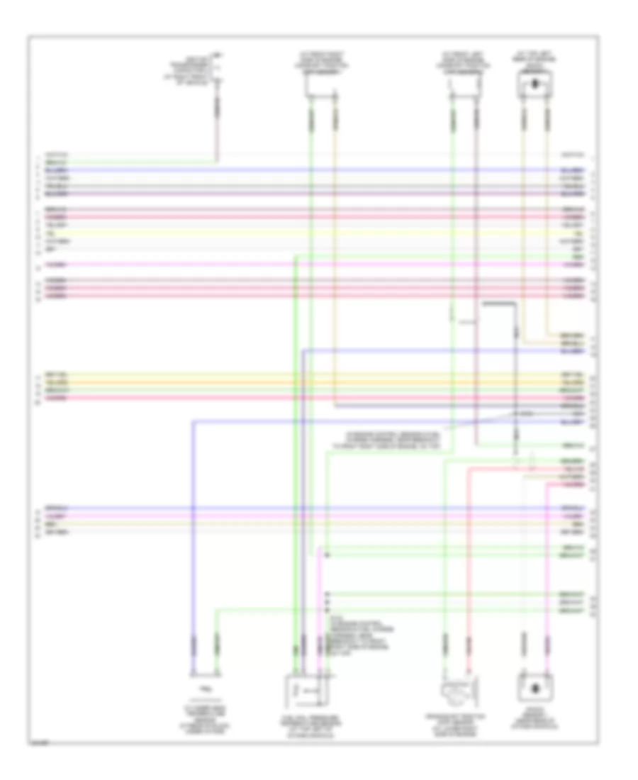
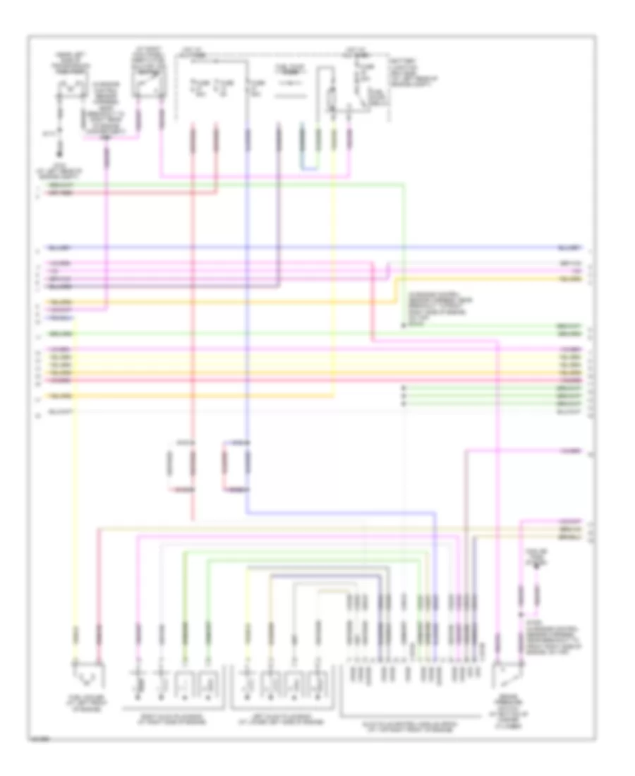
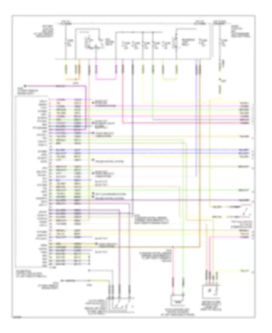
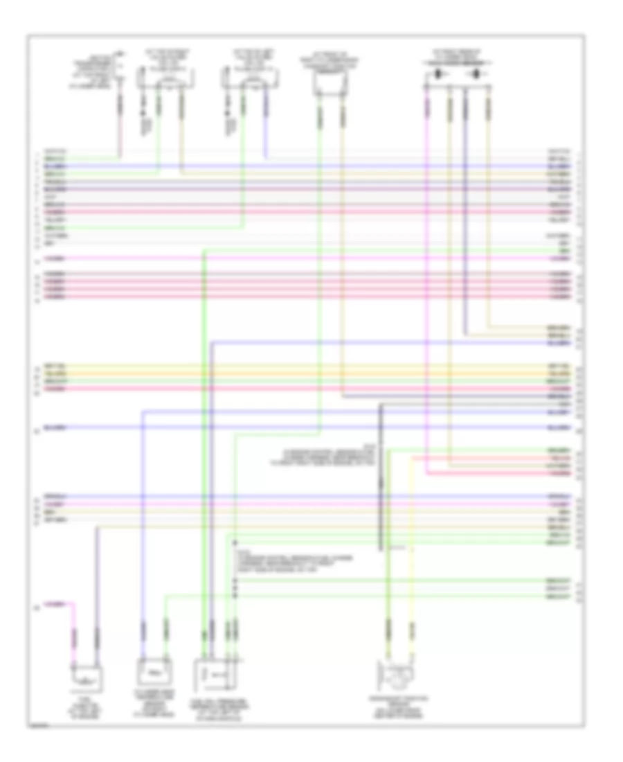
5.4L, Engine Performance Wiring Diagram (1 of 6) for Ford Cab & Chassis F350 Super Duty 2008
 https://portal-diagnostov.com/license.html
Automotive Electricians Portal FZCO
Automotive Electricians Portal FZCO
https://portal-diagnostov.com/license.html
https://portal-diagnostov.com/license.html
Automotive Electricians Portal FZCO
Automotive Electricians Portal FZCO
List of elements for 5.4L, Engine Performance Wiring Diagram (1 of 6) for Ford Cab & Chassis F350 Super Duty 2008:
- Anti-lock brakes system
- App1
- App2
- App3
- Battery junction box (bjb) (at left rear of engine compt)
- Boo
- C175b
- C2280b
- Canvnt
- Cat15
- Cbb71
- Cbb76
- Ccb08
- Cdb08
- Cdc12
- Ce114
- Ce237
- Ce326
- Ce903
- Ce904
- Ce912
- Ce913
- Ce914
- Ce924
- Cet21
- Cls05
- Cls28
- Clutch pedal position switch (m/t) (behind left side of dash, above clutch pedal)
- Computer data lines system
- Cpp bt
- Cpp tt
- Cruise control system
- Cto
- Etcref
- Etcrtn
- Evap canister vent control solenoid (at left rear side of frame)
- Exterior lights system
- Fpc
- Fpm
- Ftpt
- Ftptref
- Fuse 10a
- Fuse 15a
- Fuse 20a
- Fuse 30a
- Fuse 5a
- G103 (at right rear of engine compt)
- G106 (at right rear of engine compt)
- Gd113
- Gd164
- Gnd
- Hot at all times
- Hot in run or start
- Hs can +
- Hs can -
- Isp r
- Kapwr
- Le136
- Le137
- Le230
- Nca
- Neutral
- Park
- Pcm power relay
- Pcmrc
- Peps
- Powertrain control module (pcm) (at left side of firewall)
- Pto engage
- Pto okay
- Pto req
- Pto rpm
- Re136
- Re137
- Re407
- Res08
- Reversing lamp relay
- Rlc
- S102 (in engine control sensor harness, near breakout to right rear of engine compt)
- S154
- S158 (in engine control sensor harness, near breakout to left front corner of vehicle)
- S162
- S227
- Sbb36
- Sccs
- Sccsrtn
- Se/smc
- Sigrtnc
- Smart junction box (on passenger side kick panel)
- Tcs
- Tow haul switch (at top of steering column)
- Vdb04
- Vdb05
- Ve225
- Ve518
- Ve701
- Ve702
- Ve703
- Ve822
- Ve922
- Ves10
- Vmc05
- Vpwr1-a
- Vpwr1-b
- Vsout
- Vss
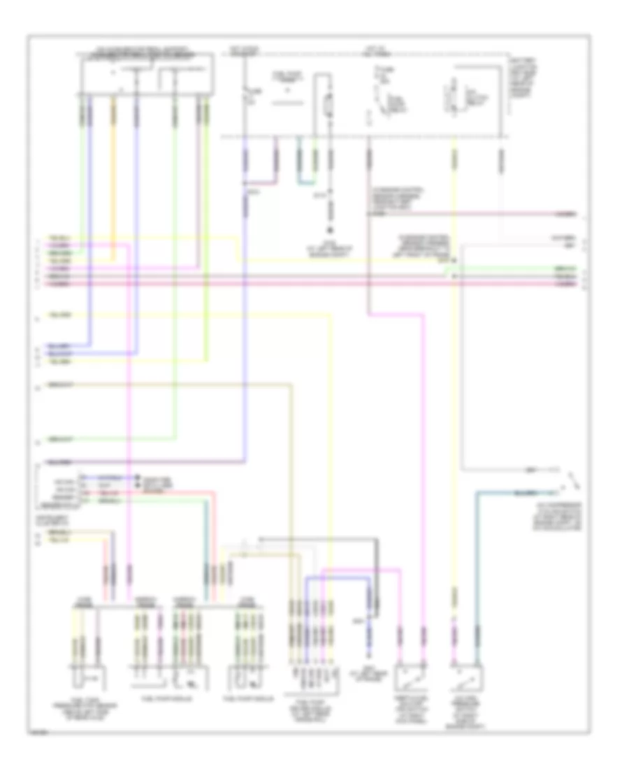
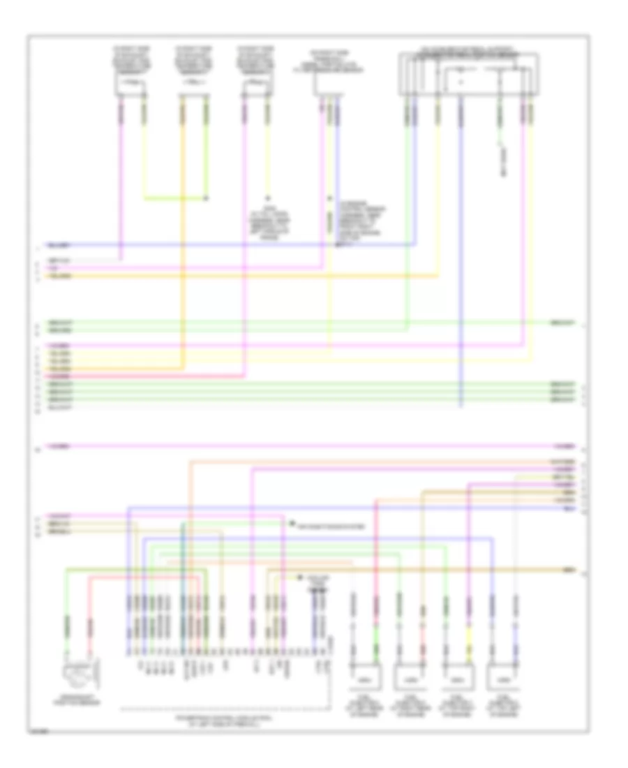
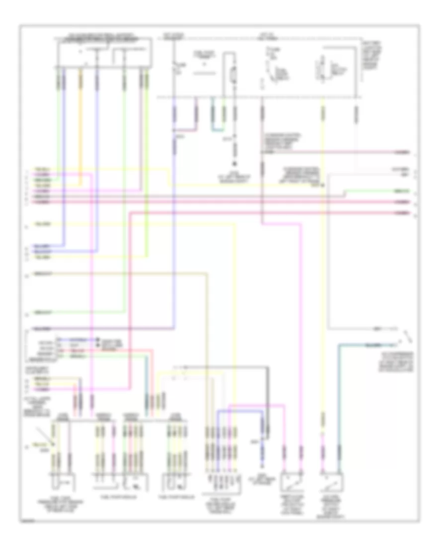
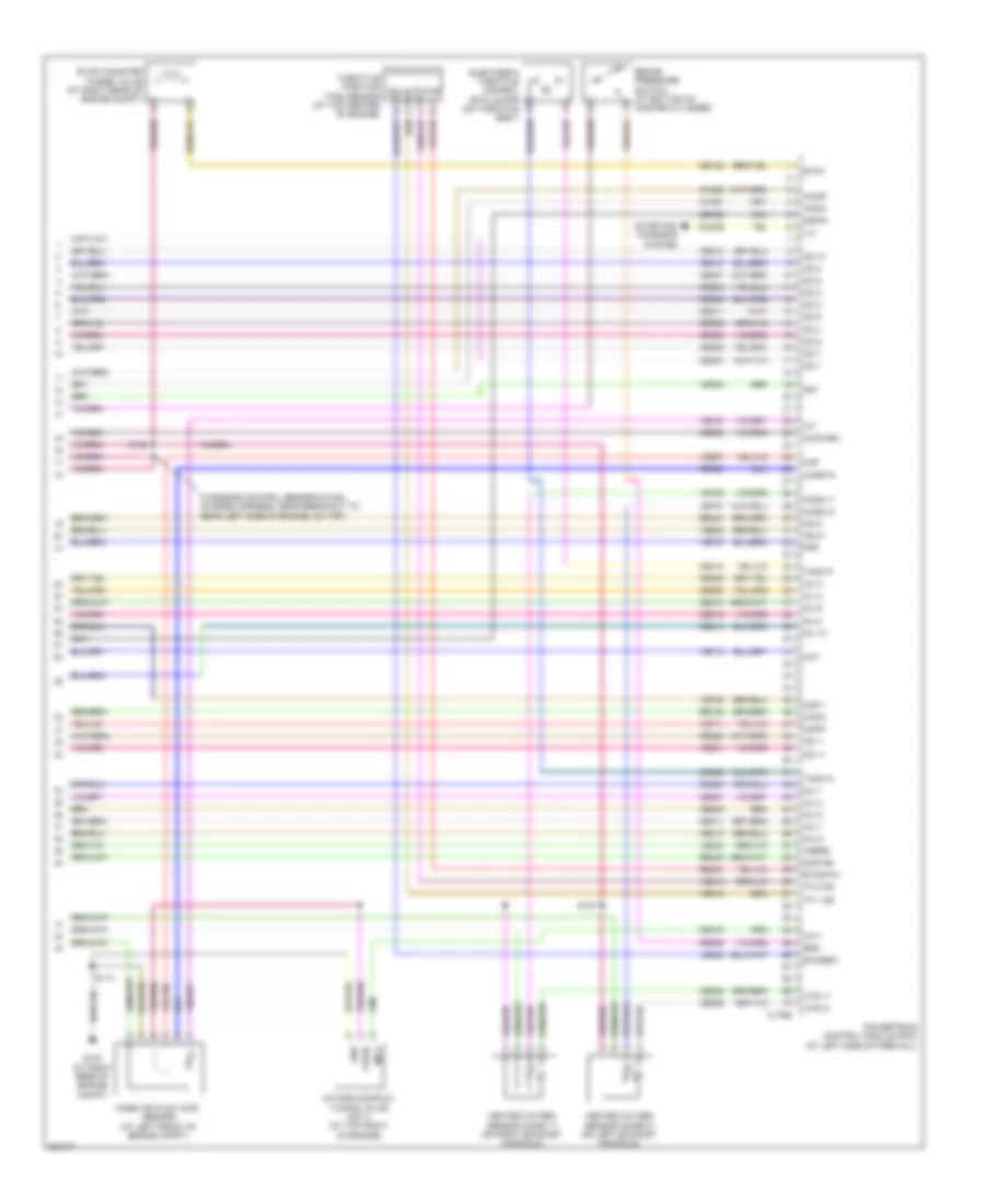
5.4L, Engine Performance Wiring Diagram (2 of 6) for Ford Cab & Chassis F350 Super Duty 2008
 https://portal-diagnostov.com/license.html
Automotive Electricians Portal FZCO
Automotive Electricians Portal FZCO
https://portal-diagnostov.com/license.html
https://portal-diagnostov.com/license.html
Automotive Electricians Portal FZCO
Automotive Electricians Portal FZCOList of elements for 5.4L, Engine Performance Wiring Diagram (2 of 6) for Ford Cab & Chassis F350 Super Duty 2008:
- (in engine control sensor harness, near battery junction box) s156
- (in engine control sensor harness, near breakout to left front of frame) s101
- (on accelerator pedal support) accelerator pedal position sensor
- A/c clutch relay
- A/c compressor cycling switch (at right rear of engine compt, on a/c accumulator)
- A/c high pressure switch (at right side of engine compt)
- Batt
- Battery junction box (bjb) (at left rear of engine compt)
- Ce515
- Ce911
- Computer data lines system
- Fp pwr
- Fpc
- Fpm
- Fpm rtn
- Fuel pump diode
- Fuel pump driver module (at left rear frame rail)
- Fuel pump module
- Fuel pump relay
- Fuel tank pressure (ftp) sensor (above left side of rear axle)
- Fuse 20a
- Fuse 5a
- G108 (at left rear of engine compt)
- G401 (at left rear of frame)
- Gd117
- Hot at all times
- Hot in run or start
- Hs can +
- Hs can -
- Inertia fuel shutoff (ifs) switch (at right kick panel)
- Instrument cluster (ic)
- Le230
- Md grd
- Narrow frame
- Nca
- Re407
- Re515
- Rmc32
- S115
- S123
- S401
- Sender 1
- Sender rtn 2
- Ve225
- Ve518
- Ve922
- Vmc11
- Wide frame
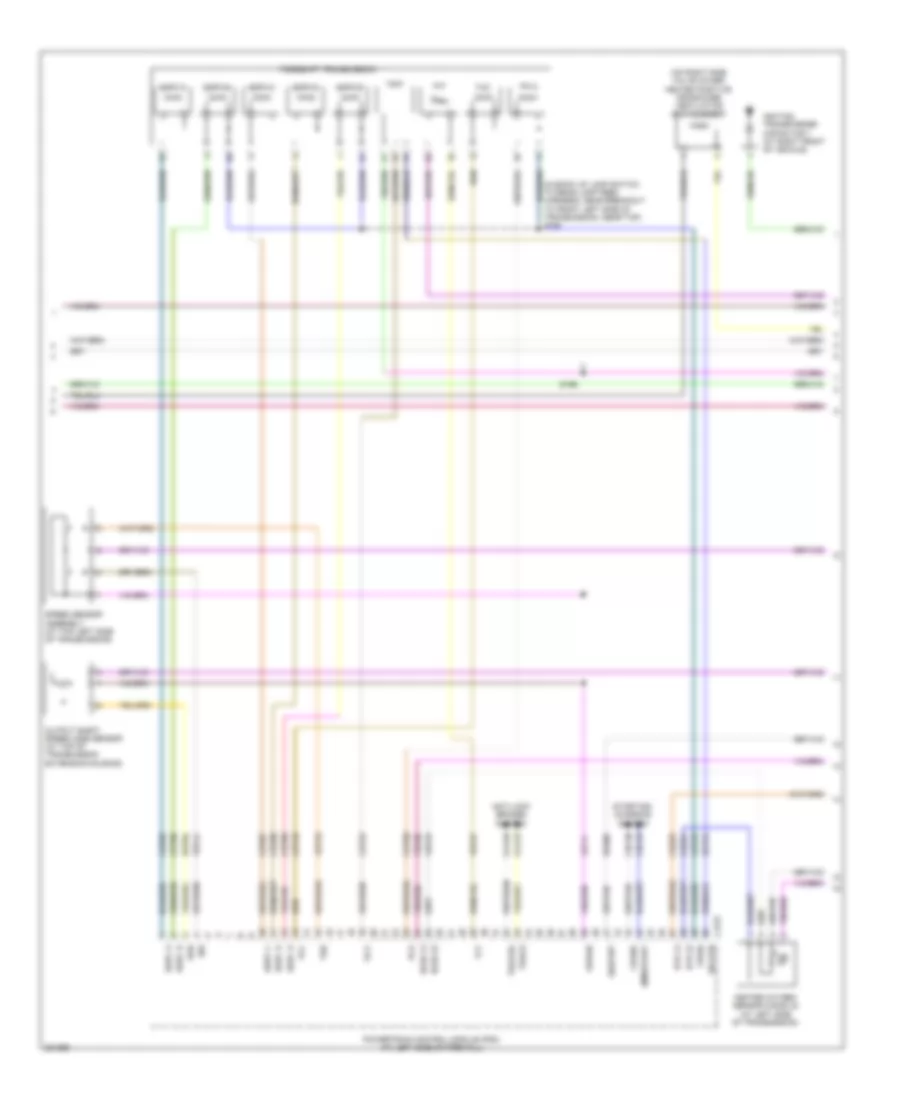
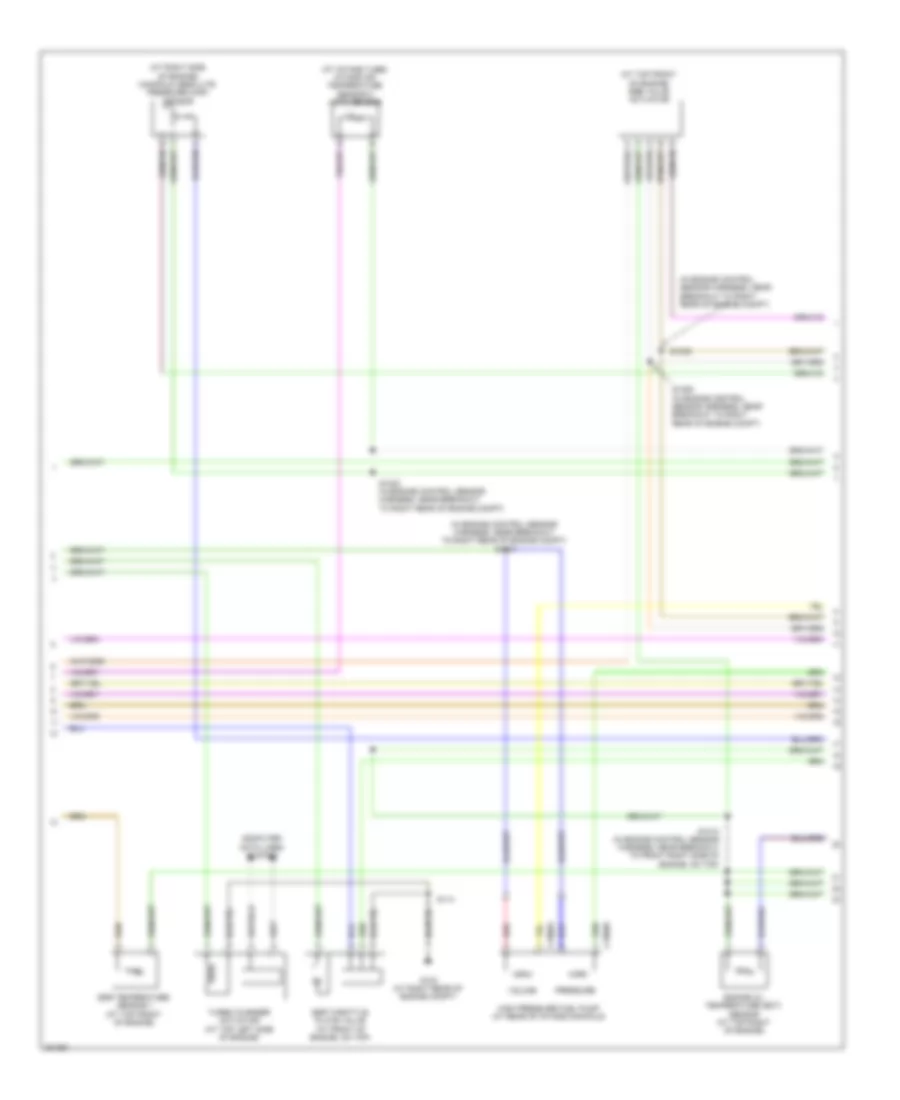
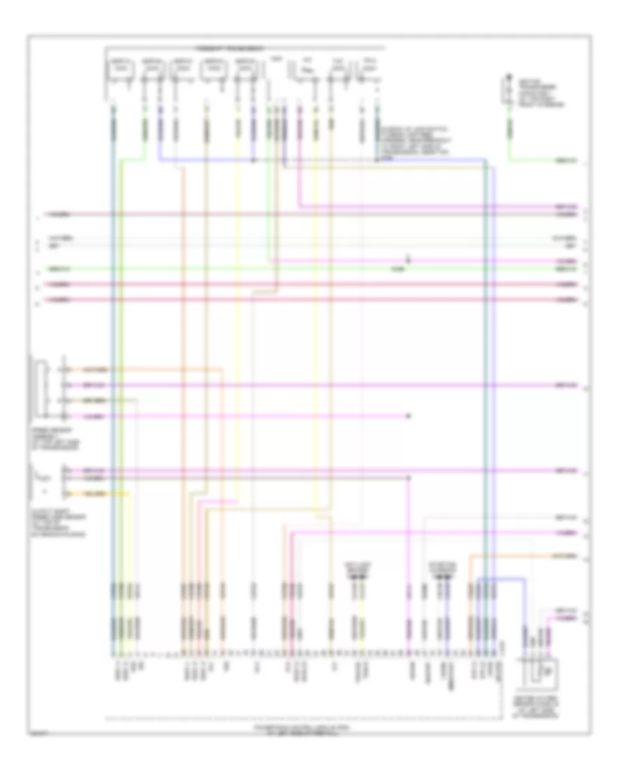
5.4L, Engine Performance Wiring Diagram (3 of 6) for Ford Cab & Chassis F350 Super Duty 2008
 https://portal-diagnostov.com/license.html
Automotive Electricians Portal FZCO
Automotive Electricians Portal FZCO
https://portal-diagnostov.com/license.html
https://portal-diagnostov.com/license.html
Automotive Electricians Portal FZCO
Automotive Electricians Portal FZCOList of elements for 5.4L, Engine Performance Wiring Diagram (3 of 6) for Ford Cab & Chassis F350 Super Duty 2008:
- (in back up lamp switch to rear lamp feed harness, near breakout to front left side of transmission, near top) s194
- (on right side valve cover) heated positive crankcase ventilation (pcv) element
- Anti-lock brakes system
- C175t
- Cca10
- Cca15
- Cdc35
- Cdc38
- Ce233
- Ce234
- Cet05
- Cet06
- Cet07
- Cet08
- Cet09
- Cet22
- Cet25
- Cet49
- Cet50
- Crank
- Heated oxygen sensor (ho2s) 22 (at left side of transmission)
- Ho2s 12
- Ho2s 22
- Htr 12
- Htr 22
- Ignition transformer capacitor 1 (at right front of vehicle)
- Iss
- Le111
- Oss
- Output shaft speed (oss) sensor (at top of transmission extension housing)
- Pc-a
- Pca
- Powertrain control module (pcm) (at left side of firewall)
- Re406
- Ret04
- Ret24
- S196
- Sig rtn
- Sigrtnt
- Smr/start
- Speed sensor assembly (at top left side of transmission)
- Sspc a
- Sspc b
- Sspc c
- Sspc d
- Sspc e
- Sspc-a
- Sspc-b
- Sspc-c
- Sspc-d
- Sspc-e
- Starting/ charging system
- Tcc
- Tft
- Torqshift transmission
- Tr p
- Tr-p
- Tracs
- Tracsil
- Tss
- Vbpwr
- Ve730
- Ve733
- Ve744
- Vet27
- Vet33
- Vpwr
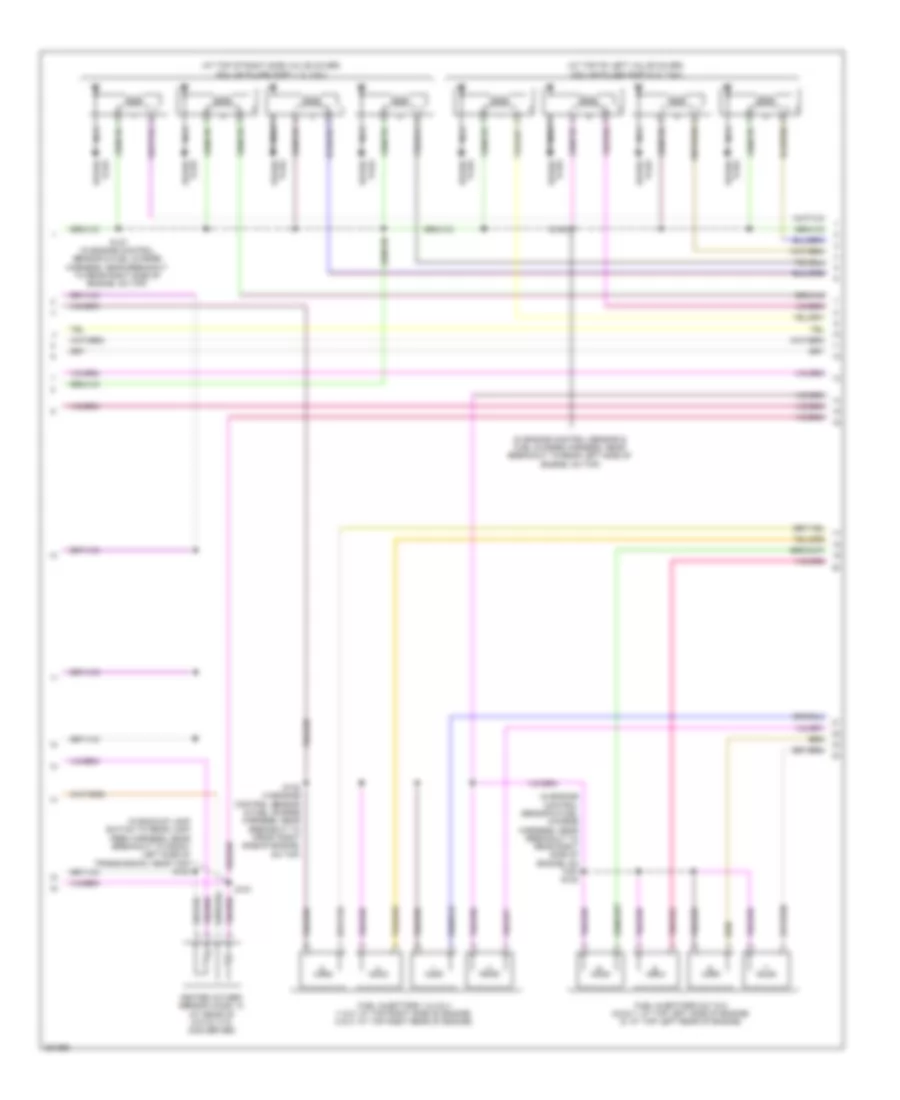
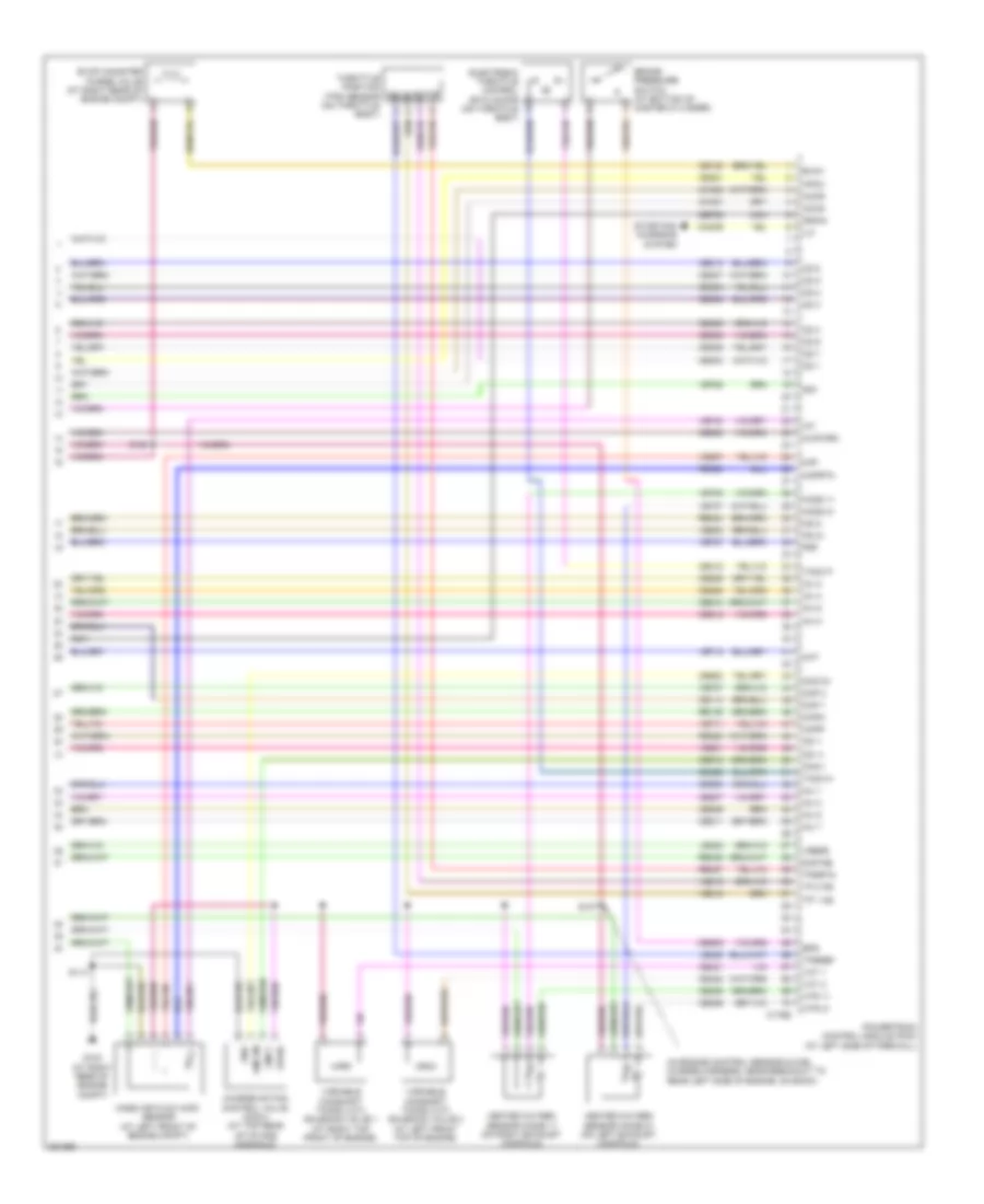
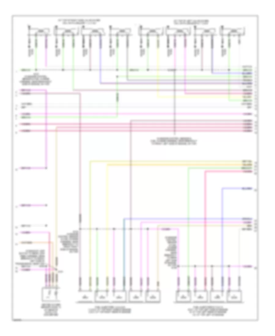
5.4L, Engine Performance Wiring Diagram (4 of 6) for Ford Cab & Chassis F350 Super Duty 2008
 https://portal-diagnostov.com/license.html
Automotive Electricians Portal FZCO
Automotive Electricians Portal FZCO
https://portal-diagnostov.com/license.html
https://portal-diagnostov.com/license.html
Automotive Electricians Portal FZCO
Automotive Electricians Portal FZCOList of elements for 5.4L, Engine Performance Wiring Diagram (4 of 6) for Ford Cab & Chassis F350 Super Duty 2008:
- (at top of left valve cover) coil on plugs (cop) 5, 6, 7 & 8
- (at top of right side valve cover) coil on plugs (cop) 1, 2, 3 & 4
- (in backup lamp switch to rear lamp feed harness, near breakout to front left side of transmission, near top) s183
- (in engine control sensor & fuel charge harness, near breakout to rear left side of engine, on top)
- (in engine control sensor & fuel charge harness, near breakout to rear right side of engine, on top) s108
- Fuel injectors 1,2,3 & 4 (1 & 2: at top right side of engine) (3 & 4: at top right rear of engine)
- Fuel injectors 5,6,7 & 8 (5,6 & 7: at top left side of engine) (8: at top left rear of engine)
- Heated oxygen sensor (ho2s) 12 (at rear of catalytic converter)
- Nca
- Plug spark
- S127 (in engine control sensor & fuel charge harness, near breakout to rear right side of engine, on top)
- S132 (in engine control sensor & fuel charge harness, near breakout to front right side of engine, on top)
- S135
- S181
- Spark plug
5.4L, Engine Performance Wiring Diagram (5 of 6) for Ford Cab & Chassis F350 Super Duty 2008
 https://portal-diagnostov.com/license.html
Automotive Electricians Portal FZCO
Automotive Electricians Portal FZCO
https://portal-diagnostov.com/license.html
https://portal-diagnostov.com/license.html
Automotive Electricians Portal FZCO
Automotive Electricians Portal FZCOList of elements for 5.4L, Engine Performance Wiring Diagram (5 of 6) for Ford Cab & Chassis F350 Super Duty 2008:
- (at front left side of engine) camshaft position (ckp) sensor 2
- (at front right side of engine) camshaft position (ckp) sensor 1
- (at top left rear of engine) knock sensor 2
- (in engine control sensor & fuel charge harness, near breakout to front right side of engine, on top)
- Crankshaft position (cmp) sensor (at lower right side of engine)
- Cylinder head temperature sensor (at rear of block, under intake)
- Fuel rail pressure/ temperature sensor (at top left of intake manifold)
- Ignition transformer capacitor 2 (at right front of vehicle)
- Knock sensor 1 (near rear of intake manifold)
- Nca
- S133 (in engine control sensor & fuel charge harness, near breakout to front right side of engine, on top)
- S134
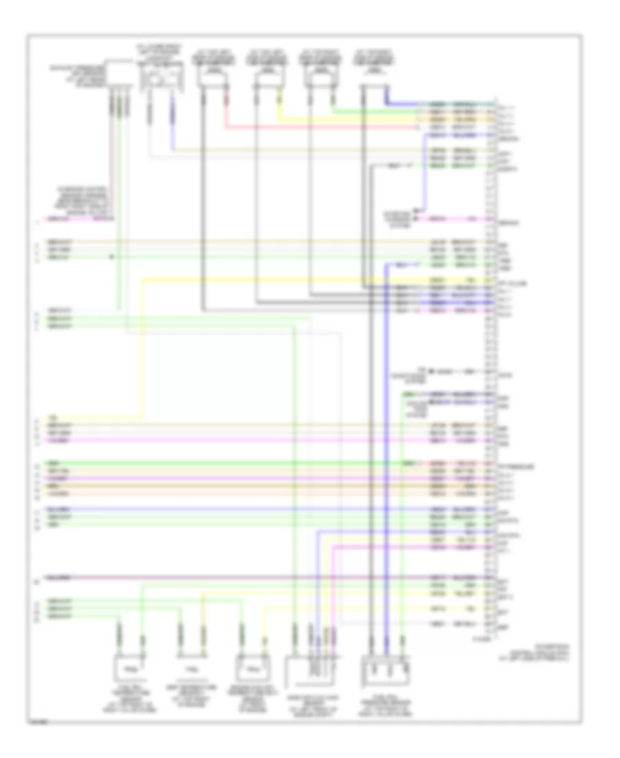
5.4L, Engine Performance Wiring Diagram (6 of 6) for Ford Cab & Chassis F350 Super Duty 2008
 https://portal-diagnostov.com/license.html
Automotive Electricians Portal FZCO
Automotive Electricians Portal FZCO
https://portal-diagnostov.com/license.html
https://portal-diagnostov.com/license.html
Automotive Electricians Portal FZCO
Automotive Electricians Portal FZCOList of elements for 5.4L, Engine Performance Wiring Diagram (6 of 6) for Ford Cab & Chassis F350 Super Duty 2008:
- (in engine control sensor & fuel charge harness, near breakout to rear left side of engine, on back)
- Accr
- Accs
- Bps
- Brake pressure switch (at bottom of master cylinder)
- C175e
- Cac09
- Cd 1
- Cd 2
- Cd 3
- Cd 4
- Cd 5
- Cd 6
- Cd 7
- Cd 8
- Ce114
- Ce132
- Ce205
- Ce206
- Ce207
- Ce208
- Ce209
- Ce210
- Ce211
- Ce212
- Ce235
- Ce236
- Ce303
- Ce304
- Ce305
- Ce306
- Ce307
- Ce308
- Ce309
- Ce310
- Ce321
- Ce412
- Ce421
- Ce422
- Ce426
- Ce608
- Ce918
- Ce923
- Ces09
- Ch302
- Ch421
- Charge motion control valve (cmcv) (at top rear of intake manifold)
- Cht
- Ckpn
- Ckpp
- Cmcv
- Cmcvm
- Cmp 1
- Cmp 2
- De706
- Drain
- Evap canister purge valve (at right rear of engine compt)
- Evmv
- Frp
- Frt
- G103 (at right rear of engine compt)
- Gnd
- Heated oxygen sensor (ho2s) 11 (on right exhaust manifold)
- Heated oxygen sensor (ho2s) 21 (on left exhaust manifold)
- Ho2s 11
- Ho2s 21
- Hpcc
- Htr 11
- Htr 21
- Iat
- Ilc
- Inj 1
- Inj 2
- Inj 3
- Inj 4
- Inj 5
- Inj 6
- Inj 7
- Inj 8
- Injpwrm
- Ks 1+
- Ks 1-
- Ks 2+
- Ks 2-
- Le423
- Le428
- Maf
- Mafrtn
- Mass air flow (maf) sensor (at left front of engine compt)
- Nca
- Powertrain control module (pcm) (at left side of firewall)
- Re135
- Re320
- Re323
- Re324
- Re405
- Re427
- S107
- S114
- S155
- Sigtne
- Solid state
- Starting/ charging system
- Tacm n
- Tacm p
- Throttle position (tps) sensor (on throttle body)
- Tp 1 ns
- Tp 2 ps
- Tpsref
- Tpsrtn
- Variable camshaft timing (vct) solenoid valve 1 (at right top front of engine)
- Variable camshaft timing (vct) solenoid valve 2 (at left front top of engine)
- Vct 1
- Vct 2
- Ve707
- Ve711
- Ve712
- Ve727
- Ve728
- Ve735
- Ve737
- Ve740
- Ve801
- Ve802
- Ve807
- Ve818
- Ve819
- Vpwr
- Vrefe
6.4L DIESEL
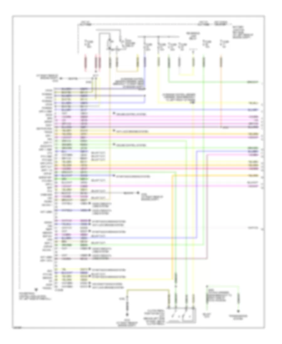
6.4L Diesel, Engine Performance Wiring Diagram (1 of 6) for Ford Cab & Chassis F350 Super Duty 2008
 https://portal-diagnostov.com/license.html
Automotive Electricians Portal FZCO
Automotive Electricians Portal FZCO
https://portal-diagnostov.com/license.html
https://portal-diagnostov.com/license.html
Automotive Electricians Portal FZCO
Automotive Electricians Portal FZCOList of elements for 6.4L Diesel, Engine Performance Wiring Diagram (1 of 6) for Ford Cab & Chassis F350 Super Duty 2008:
- (at right rear of engine compt) g103
- (in engine control sensor harness, near breakout to left front of frame) s101
- (in engine control sensor harness, near breakout to right rear of engine compt) s102
- Accr
- Air conditioning system
- Anti-lock brakes system
- App 1
- App 1 rtn
- App 1 vref
- App 2
- App 2 rtn
- App 2 vref
- Battery junction box (bjb) (at left rear of engine compt)
- Bcp il
- Bcp sw
- Bpp
- Bps
- C1232b
- Case gnd
- Cbb71
- Cbb76
- Cca10
- Cca15
- Ccb06
- Cdc12
- Cdc35
- Cdc38
- Cdc46
- Cdc47
- Ce140
- Ce237
- Ce326
- Ce904
- Ce911
- Ce912
- Ce913
- Ce914
- Ce925
- Ces09
- Cet21
- Ch302
- Clutch pedal position switch (m/t) (behind left side of dash, above clutch pedal)
- Cmc25
- Computer data lines system
- Cpp bt
- Cpp tt
- Crank
- Cruise control system
- Cto
- Doct
- Dpfdp
- Dpft 1 in
- Dpft out
- Fpm
- Fuse 10a
- Fuse 20a
- Fuse 50a
- Fuse 5a
- G103 (at right rear of engine compt)
- G106 (at right rear of engine compt)
- Gd113
- Gd164
- Gencom
- Genmon
- Hot at all times
- Hot in run or start
- Hs can +
- Hs can -
- Kapwr
- Keypwr (r/s)
- Le136
- Le137
- Le434
- Not used
- Pbpp
- Pcm power relay
- Pcmrc
- Powertrain control module (pcm) (at left side of firewall)
- Pto
- Pto gnd
- Pto ind
- Pto rpm
- Pto vref
- Pwrgnd
- Re136
- Re137
- Re327
- Res08
- Reversing lamp relay
- S117
- S123
- S162
- S208 (in main harness, near breakout to right side of hvac housing)
- Sbb36
- Sccs
- Sccs rtn
- Smc
- Smr/start
- Starting/charging system
- Tracs
- Tracsil
- Transmissions system
- Vdb04
- Vdb05
- Ve225
- Ve701
- Ve702
- Ve746
- Ve747
- Ve748
- Ve749
- Ve822
- Ve823
- Ves10
- Vmv05
- Vpwr
- Vso
- Vss
- Wfs
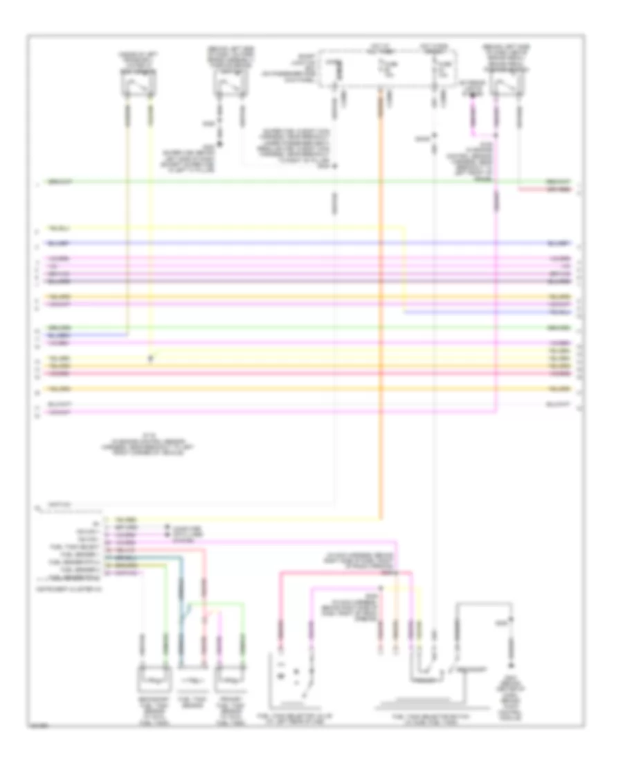
6.4L Diesel, Engine Performance Wiring Diagram (2 of 6) for Ford Cab & Chassis F350 Super Duty 2008
 https://portal-diagnostov.com/license.html
Automotive Electricians Portal FZCO
Automotive Electricians Portal FZCO
https://portal-diagnostov.com/license.html
https://portal-diagnostov.com/license.html
Automotive Electricians Portal FZCO
Automotive Electricians Portal FZCOList of elements for 6.4L Diesel, Engine Performance Wiring Diagram (2 of 6) for Ford Cab & Chassis F350 Super Duty 2008:
- (behind left side of dash, above brake pedal) brake pedal position switch
- (behind left side of dash, on park brake assembly) parking brake switch
- (in main harness, behind right side of dash, right of radio opening)
- (inside of left frame rail) water in fuel sensor
- (super cab: in body main harness, near breakout under passenger seat) (regular cab: in body main harness, near breakout to right "b" pillar) s304
- C2280a
- C2280b
- C2280c
- Computer data lines system
- Exterior lights system
- Fuel sender 1
- Fuel sender 2
- Fuel sender rtn 2
- Fuel tank select
- Fuel tank selector switch (w/ duel fuel tank)
- Fuel tank selector valve (at left rear of cab)
- Fuel tank sensor
- Fuse 10a
- G203 (behind center of dash, behind audio control module)
- G300 (super cab: behind left side of dash) (except super cab: in left "a" pillar)
- Hot at all times
- Hot in run or acc
- Instrument cluster (ic)
- Micro
- Ms can +
- Ms can -
- Primary
- Primary fuel tank sensor (w/ dual fuel tank)
- S106 (in engine control sensor harness, near breakout to left front of frame)
- S116 (in engine control sensor harness, near breakout to left front corner of vehicle)
- S225
- S2439
- S245
- S246 (in main harness, behind right side of dash, right of radio opening)
- S326
- Secondary
- Secondary fuel tank sensor (w/ dual fuel tank)
- Sense
- Smart junction box (on passenger side kick panel)
6.4L Diesel, Engine Performance Wiring Diagram (3 of 6) for Ford Cab & Chassis F350 Super Duty 2008
 https://portal-diagnostov.com/license.html
Automotive Electricians Portal FZCO
Automotive Electricians Portal FZCO
https://portal-diagnostov.com/license.html
https://portal-diagnostov.com/license.html
Automotive Electricians Portal FZCO
Automotive Electricians Portal FZCOList of elements for 6.4L Diesel, Engine Performance Wiring Diagram (3 of 6) for Ford Cab & Chassis F350 Super Duty 2008:
- (at right kick panel) inertia fuel shutoff (ifs) switch
- (in engine control sensor harness, near breakout to front right side of engine, on top) s1010
- (in engine control sensor harness, near breakout to right rear of engine compartment) s107
- (near left side of transmission) fuel pump
- Battery junction box (bjb) (at left rear of engine compt)
- Brake pressure switch (at bottom of master cylinder)
- C1273a
- C1273b
- Cbb12
- Ce243
- Ce244
- Ce245
- Ce246
- Ce247
- Ce248
- Ce251
- Ce252
- Ce513
- Ce514
- Cooling fans system
- Fuel cooler (at left front of engine)
- Fuel pump diode
- Fuel pump relay
- Fuse 20a
- Fuse 50a
- Fuse 5a
- G104 (at left rear of engine compt)
- Glow plug control module (gpcm) (at top right front of engine)
- Gpd
- Gpe
- Hot at all times
- Kapwr
- Left glow plug bank (at lower left side of engine)
- Right glow plug bank (at right side of engine)
- S1000
- S1003
- S1009 (in engine control sensor harness, near breakout to front right side of engine, on top)
- S103
- S113
- S124
- Sbb27
- Sbb47
- Vpwr
6.4L Diesel, Engine Performance Wiring Diagram (4 of 6) for Ford Cab & Chassis F350 Super Duty 2008
 https://portal-diagnostov.com/license.html
Automotive Electricians Portal FZCO
Automotive Electricians Portal FZCO
https://portal-diagnostov.com/license.html
https://portal-diagnostov.com/license.html
Automotive Electricians Portal FZCO
Automotive Electricians Portal FZCOList of elements for 6.4L Diesel, Engine Performance Wiring Diagram (4 of 6) for Ford Cab & Chassis F350 Super Duty 2008:
- (in engine control sensor harness, near breakout to front right side of engine, on top) s114
- (in right side of exhaust) exhaust gas temperature sensor 1
- (in right side of exhaust) exhaust gas temperature sensor 2
- (in right side of exhaust) exhaust gas temperature sensor 3
- (not used)
- (on accelerator pedal support) accelerator pedal position sensor
- (on right side frame rail) diesel particulate filter pressure sensor
- Acp sw
- Air conditioning system
- C1232e
- Ce250
- Ce315
- Ce514
- Cec11
- Ch425
- Ckp +
- Ckp -
- Cooling fans system
- Crankshaft position sensor
- Ctrl
- Egrvp
- Egt 1
- Fcc
- Fuel injector 2 (at top left of engine)
- Fuel injector 3 (at top right of engine)
- Fuel injector 5 (at right rear of engine)
- Fuel injector 8 (at left rear of engine)
- Gpd
- Iat 2
- Inj 2 -
- Inj 3 -
- Inj 5 -
- Inj 8 -
- Powertrain control module (pcm) (at left side of firewall)
- Re135
- Re206
- Re207
- Re209
- Re212
- Red
- S408 (in tail lamps harness, near breakout to left middle of frame)
- Sig
- Vbpwr
- Ve711
- Ve721
- Ve722
- Ve740
- Vec03
- Vec10
6.4L Diesel, Engine Performance Wiring Diagram (5 of 6) for Ford Cab & Chassis F350 Super Duty 2008
 https://portal-diagnostov.com/license.html
Automotive Electricians Portal FZCO
Automotive Electricians Portal FZCO
https://portal-diagnostov.com/license.html
https://portal-diagnostov.com/license.html
Automotive Electricians Portal FZCO
Automotive Electricians Portal FZCOList of elements for 6.4L Diesel, Engine Performance Wiring Diagram (5 of 6) for Ford Cab & Chassis F350 Super Duty 2008:
- (at intake tube) intake air temperature sensor 2 (iat2) sensor
- (at right side of engine) manifold absolute pressure (map) sensor
- (at top front of engine) egr valve actuator
- (in engine control sensor harness, near breakout to right rear of engine compt)
- (in engine control sensor harness, near breakout to right rear of engine compt) s1007
- C1906a
- C1906b
- Computer data lines system
- Egr temperature sensor 1 (at top front of engine)
- Egr throttle plate valve (at front of engine, on top)
- Engine oil temperature (eot) sensor (at top right of engine)
- G103 (at right rear of engine compt)
- High pressure fuel pump (at rear of intake manifold)
- Pressure
- Red
- S1002 (in engine control sensor harness, near breakout to right rear of engine compt)
- S1005
- S1006 (in engine control sensor harness, near breakout to right rear of engine compt)
- S1013 (in engine control sensor harness, near breakout to front right side of engine, on top)
- S114
- Turbo charger actuator (at top left side of engine)
- Volume
6.4L Diesel, Engine Performance Wiring Diagram (6 of 6) for Ford Cab & Chassis F350 Super Duty 2008
 https://portal-diagnostov.com/license.html
Automotive Electricians Portal FZCO
Automotive Electricians Portal FZCO
https://portal-diagnostov.com/license.html
https://portal-diagnostov.com/license.html
Automotive Electricians Portal FZCO
Automotive Electricians Portal FZCOList of elements for 6.4L Diesel, Engine Performance Wiring Diagram (6 of 6) for Ford Cab & Chassis F350 Super Duty 2008:
- (at lower front left of engine) camshaft position sensor
- (at top left rear of engine) fuel injector 6
- (at top left side of engine) fuel injector 4
- (at top right rear of engine) fuel injector 7
- (at top right side of engine) fuel injector 1
- (in engine control sensor harness, near breakout to front right side of engine, on top) s1012
- Accs
- Air conditioning system
- C1232e
- Cdc10
- Cdc15
- Ce205
- Ce206
- Ce207
- Ce208
- Ce209
- Ce210
- Ce211
- Ce212
- Ce316
- Ce321
- Ce328
- Ch421
- Cmp +
- Cmp -
- Cooling fans system
- Ebp
- Ect
- Egr temperature sensor 2 (at top front of engine)
- Egt 2
- Engine coolant temperature (ect) sensor (at front of engine)
- Eot
- Exhaust pressure (ep) sensor (at left rear of engine)
- Frpi
- Frt
- Fuel rail pressure sensor (at top right of right valve cover)
- Fuel rail temperature sensor (at top right of right valve cover)
- Gd119
- Ge513
- Gencom
- Genmon
- Gnd
- Gpe
- Iat 1
- Inj 1 +
- Inj 1 -
- Inj 2 +
- Inj 3 +
- Inj 4 +
- Inj 4 -
- Inj 5 +
- Inj 6 +
- Inj 6 -
- Inj 7 +
- Inj 7 -
- Inj 8 +
- Le139
- Le423
- Lr139
- Maf
- Maf rtn
- Map
- Mass air flow (maf) sensor (at left front of engine compt)
- Powertrain control module (pcm) (at left side of firewall)
- Pp pressure
- Pp volume
- Re139
- Re205
- Re208
- Re210
- Re211
- Re230
- Re405
- Re406
- Re429
- Red
- Ref
- Rtn
- Sig
- Sig rtn
- Sigrtn
- Starting/ charging system
- Ve607
- Ve706
- Ve716
- Ve717
- Ve726
- Ve727
- Ve728
- Ve740
- Ve803
- Ve921
- Vref
6.8L
6.8L, Engine Performance Wiring Diagram (1 of 6) for Ford Cab & Chassis F350 Super Duty 2008
 https://portal-diagnostov.com/license.html
Automotive Electricians Portal FZCO
Automotive Electricians Portal FZCO
https://portal-diagnostov.com/license.html
https://portal-diagnostov.com/license.html
Automotive Electricians Portal FZCO
Automotive Electricians Portal FZCOList of elements for 6.8L, Engine Performance Wiring Diagram (1 of 6) for Ford Cab & Chassis F350 Super Duty 2008:
- Anti-lock brakes system
- App1
- App2
- App3
- Battery junction box (bjb) (at left rear of engine compt)
- Boo
- C175b
- C2280b
- Canvnt
- Cat15
- Cbb71
- Cbb76
- Ccb08
- Cdb08
- Cdc12
- Ce114
- Ce237
- Ce239
- Ce326
- Ce903
- Ce904
- Ce912
- Ce913
- Ce914
- Ce924
- Cet21
- Cls05
- Cls28
- Clutch pedal position switch (m/t) (behind left side of dash, above clutch pedal)
- Computer data lines system
- Cpp bt
- Cpp tt
- Cruise control system
- Cto
- Etcref
- Etcrtn
- Evap canister vent control solenoid (at left rear side of frame)
- Fpc
- Fpm
- Ftpt
- Ftptref
- Fuse 10a
- Fuse 15a
- Fuse 20a
- Fuse 30a
- Fuse 5a
- G103 (at right rear of engine compt)
- G106 (at right rear of engine compt)
- Gd113
- Gd164
- Gnd
- Heated oxygen sensor (ho2s) 13 (under left front of vehicle)
- Ho2s 13
- Hot at all times
- Hot in run or start
- Hs can +
- Hs can -
- Htr 13
- Isp r
- Kapwr
- Le136
- Le137
- Le230
- Nca
- Neutral
- Park
- Pcm power relay
- Pcmrc
- Peps
- Powertrain control module (pcm) (at left side of firewall)
- Pto engage
- Pto okay
- Pto req
- Pto rpm
- Re136
- Re137
- Re407
- Res08
- Reversing lamp relay
- Rlc
- S102 (in engine control sensor harness, near breakout to right rear of engine compt)
- S154
- S158 (in engine control sensor harness, near breakout to left front corner of vehicle)
- S162
- S227
- Sbb36
- Sccs
- Sccsrtn
- Se/smc
- Sigrtnc
- Smart junction box (on passenger side kick panel)
- Tcs
- Tow haul switch (at top of steering column)
- Vdb04
- Vdb05
- Ve225
- Ve518
- Ve701
- Ve702
- Ve703
- Ve745
- Ve822
- Ve922
- Ves10
- Vmc05
- Vpwr1-a
- Vpwr1-b
- Vsout
- Vss
6.8L, Engine Performance Wiring Diagram (2 of 6) for Ford Cab & Chassis F350 Super Duty 2008
 https://portal-diagnostov.com/license.html
Automotive Electricians Portal FZCO
Automotive Electricians Portal FZCO
https://portal-diagnostov.com/license.html
https://portal-diagnostov.com/license.html
Automotive Electricians Portal FZCO
Automotive Electricians Portal FZCOList of elements for 6.8L, Engine Performance Wiring Diagram (2 of 6) for Ford Cab & Chassis F350 Super Duty 2008:
- (in engine control sensor harness, near battery junction box) s156
- (in engine control sensor harness, near breakout to left front of frame) s101
- (in tail lamps harness, near breakout to cross brace)
- (on accelerator pedal support) accelerator pedal position sensor
- A/c clutch relay
- A/c compressor cycling switch (at right rear of engine compt, on a/c accumulator)
- A/c high pressure switch (at right side of engine compt)
- Batt
- Battery junction box (bjb) (at left rear of engine compt)
- Ce515
- Ce911
- Computer data lines system
- Fp pwr
- Fpc
- Fpm
- Fpm rtn
- Fuel pump diode
- Fuel pump driver module (at left rear frame rail)
- Fuel pump module
- Fuel pump relay
- Fuel tank pressure (ftp) sensor (above left side of rear axle)
- Fuse 20a
- Fuse 5a
- G108 (at left rear of engine compt)
- G400 (at left rear of frame)
- Gd117
- Hot at all times
- Hot in run or start
- Hs can +
- Hs can -
- Inertia fuel shutoff (ifs) switch (at right kick panel)
- Instrument cluster (ic)
- Le230
- Md grd
- Narrow frame
- Nca
- Re407
- Re515
- Rmc32
- S115
- S123
- S401
- S406
- Sender 1
- Sender rtn 2
- Ve225
- Ve518
- Ve922
- Vmc11
- Wide frame
6.8L, Engine Performance Wiring Diagram (3 of 6) for Ford Cab & Chassis F350 Super Duty 2008
 https://portal-diagnostov.com/license.html
Automotive Electricians Portal FZCO
Automotive Electricians Portal FZCO
https://portal-diagnostov.com/license.html
https://portal-diagnostov.com/license.html
Automotive Electricians Portal FZCO
Automotive Electricians Portal FZCOList of elements for 6.8L, Engine Performance Wiring Diagram (3 of 6) for Ford Cab & Chassis F350 Super Duty 2008:
- (in back up lamp switch to rear lamp feed harness, near breakout to front left side of transmission, near top) s194
- Anti-lock brakes system
- C175t
- Cca10
- Cca15
- Cdc35
- Cdc38
- Ce233
- Ce234
- Cet05
- Cet06
- Cet07
- Cet08
- Cet09
- Cet22
- Cet25
- Cet49
- Cet50
- Crank
- Heated oxygen sensor (ho2s) 22 (at left side of transmission)
- Ho2s 12
- Ho2s 22
- Htr 12
- Htr 22
- Ignition transformer capacitor 1 (at top right front of engine)
- Iss
- Le111
- Oss
- Output shaft speed (oss) sensor (at top of transmission extension housing)
- Pc-a
- Pca
- Powertrain control module (pcm) (at left side of firewall)
- Re406
- Ret04
- Ret24
- S196
- Sig rtn
- Sigrtnt
- Smr/start
- Speed sensor assembly (at top left side of transmission)
- Sspc a
- Sspc b
- Sspc c
- Sspc d
- Sspc e
- Sspc-a
- Sspc-b
- Sspc-c
- Sspc-d
- Sspc-e
- Starting/ charging system
- Tcc
- Tft
- Torqshift transmission
- Tr p
- Tr-p
- Tracs
- Tracsil
- Tss
- Vbpwr
- Ve730
- Ve733
- Ve744
- Vet27
- Vet33
- Vpwr
6.8L, Engine Performance Wiring Diagram (4 of 6) for Ford Cab & Chassis F350 Super Duty 2008
 https://portal-diagnostov.com/license.html
Automotive Electricians Portal FZCO
Automotive Electricians Portal FZCO
https://portal-diagnostov.com/license.html
https://portal-diagnostov.com/license.html
Automotive Electricians Portal FZCO
Automotive Electricians Portal FZCOList of elements for 6.8L, Engine Performance Wiring Diagram (4 of 6) for Ford Cab & Chassis F350 Super Duty 2008:
- (at top of left valve cover) coil on plugs (cop) 6, 7, 8 & 9
- (at top of right side valve cover) coil on plugs (cop) 1, 2, 3 & 4
- (in backup lamp switch to rear lamp feed harness, near breakout to front left side of transmission, near top) s183
- (in engine control sensor & fuel charge harness, near breakout to front left side of engine, on top)
- (in engine control sensor & fuel charge harness, near breakout to rear left side of engine, on top) s136
- Fuel injectors 1,2,3,4 & 5 (1,2 & 5: at top right side of engine) (3 & 4: at top right rear of engine)
- Fuel injectors 6,7,8 & 10 (6 & 7: at top left side of engine) (8: at top left rear of engine) (10: at top left of engine)
- Heated oxygen sensor (ho2s) 12 (at rear of catalytic converter)
- Nca
- Plug spark
- S127 (in engine control sensor & fuel charge harness, near rear right side of engine, on top)
- S132 (in engine control sensor & fuel charge harness, near breakout to front right side of engine, on top)
- S135
- S181
- Spark plug
6.8L, Engine Performance Wiring Diagram (5 of 6) for Ford Cab & Chassis F350 Super Duty 2008
 https://portal-diagnostov.com/license.html
Automotive Electricians Portal FZCO
Automotive Electricians Portal FZCO
https://portal-diagnostov.com/license.html
https://portal-diagnostov.com/license.html
Automotive Electricians Portal FZCO
Automotive Electricians Portal FZCOList of elements for 6.8L, Engine Performance Wiring Diagram (5 of 6) for Ford Cab & Chassis F350 Super Duty 2008:
- (at front of right cylinder bank) camshaft position sensor 1
- (at right rear of cylinder head) dual knock sensor
- (at top of left valve cover) coil on plugs (cop) 10
- (at top of right valve cover) coil on plugs (cop) 5
- Crankshaft position sensor (on lower front center of engine)
- Cylinder head temperature sensor (on right cylinder head)
- Fuel injector (at top left of engine)
- Fuel rail pressure/ temperature sensor (at top left of intake manifold)
- Ignition transformer capacitor 2 (at top front of left cylinder head)
- Nca
- S133 (in engine control sensor & fuel charge harness, near breakout to front right side of engine, on top)
- S134 (in engine control sensor & fuel charge harness, near breakout to front right side of engine, on top)
- Spark plug
6.8L, Engine Performance Wiring Diagram (6 of 6) for Ford Cab & Chassis F350 Super Duty 2008
 https://portal-diagnostov.com/license.html
Automotive Electricians Portal FZCO
Automotive Electricians Portal FZCO
https://portal-diagnostov.com/license.html
https://portal-diagnostov.com/license.html
Automotive Electricians Portal FZCO
Automotive Electricians Portal FZCOList of elements for 6.8L, Engine Performance Wiring Diagram (6 of 6) for Ford Cab & Chassis F350 Super Duty 2008:
- (in engine control sensor & fuel charge harness, near breakout to rear left side of engine, on top)
- Accr
- Accs
- Bps
- Brake pressure switch (at bottom of master cylinder)
- C175e
- Cac09
- Cd 1
- Cd 10
- Cd 2
- Cd 3
- Cd 4
- Cd 5
- Cd 6
- Cd 7
- Cd 8
- Cd 9
- Ce132
- Ce205
- Ce206
- Ce207
- Ce208
- Ce209
- Ce210
- Ce211
- Ce212
- Ce213
- Ce214
- Ce235
- Ce236
- Ce303
- Ce304
- Ce305
- Ce306
- Ce307
- Ce308
- Ce309
- Ce310
- Ce311
- Ce312
- Ce316
- Ce412
- Ce426
- Ce608
- Ces09
- Ch302
- Ch421
- Cht
- Ckpn
- Ckpp
- Cmp 1
- De706
- Drain
- Etcref1
- Etcrtn1
- Evap canister purge valve (at right rear of engine compt)
- Evmv
- Frp
- Frt
- G103 (at right rear of engine compt)
- Gnd
- Heated oxygen sensor (ho2s) 11 (on right exhaust manifold)
- Heated oxygen sensor (ho2s) 21 (on left exhaust manifold)
- Ho2s 11
- Ho2s 21
- Htr 11
- Htr 21
- Iat
- Ilc
- Imtv
- Inj 1
- Inj 10
- Inj 2
- Inj 3
- Inj 4
- Inj 5
- Inj 6
- Inj 7
- Inj 8
- Inj 9
- Injpwrm
- Intake manifold tuning valve (imtv) (at top right of engine)
- Ks 1+
- Ks 1-
- Ks 2+
- Ks 2-
- Le423
- Le428
- Maf
- Mafrtn
- Mass air flow (maf) sensor (at left front of engine compt)
- Nca
- Powertrain control module (pcm) (at left side of firewall)
- Re135
- Re320
- Re323
- Re324
- Re405
- Re427
- S107
- S114
- S155
- Sigtne
- Solid state
- Starting/ charging system
- Tacm n
- Tacm p
- Throttle position (tps) sensor (at top center of engine)
- Tp 1 ns
- Tp 2 ps
- Ve706
- Ve711
- Ve712
- Ve727
- Ve728
- Ve735
- Ve737
- Ve740
- Ve801
- Ve802
- Ve807
- Ve818
- Ve819
- Vpwr
- Vrefe

 Čeština
 Dansk
Dansk Deutsch
 Ελληνικά
 English
 English
 Español
 Suomi
Suomi Français
 Français
 עברית
עברית Hrvatski
 Magyar
 Italiano
 日本語
日本語 한국어
한국어 Nederlands
 Polski
 Português
 Português
 Română
 Русский
 Slovenčina
 Slovenščina
 Svenska
 Türkçe
