ENGINE PERFORMANCE
4.0L
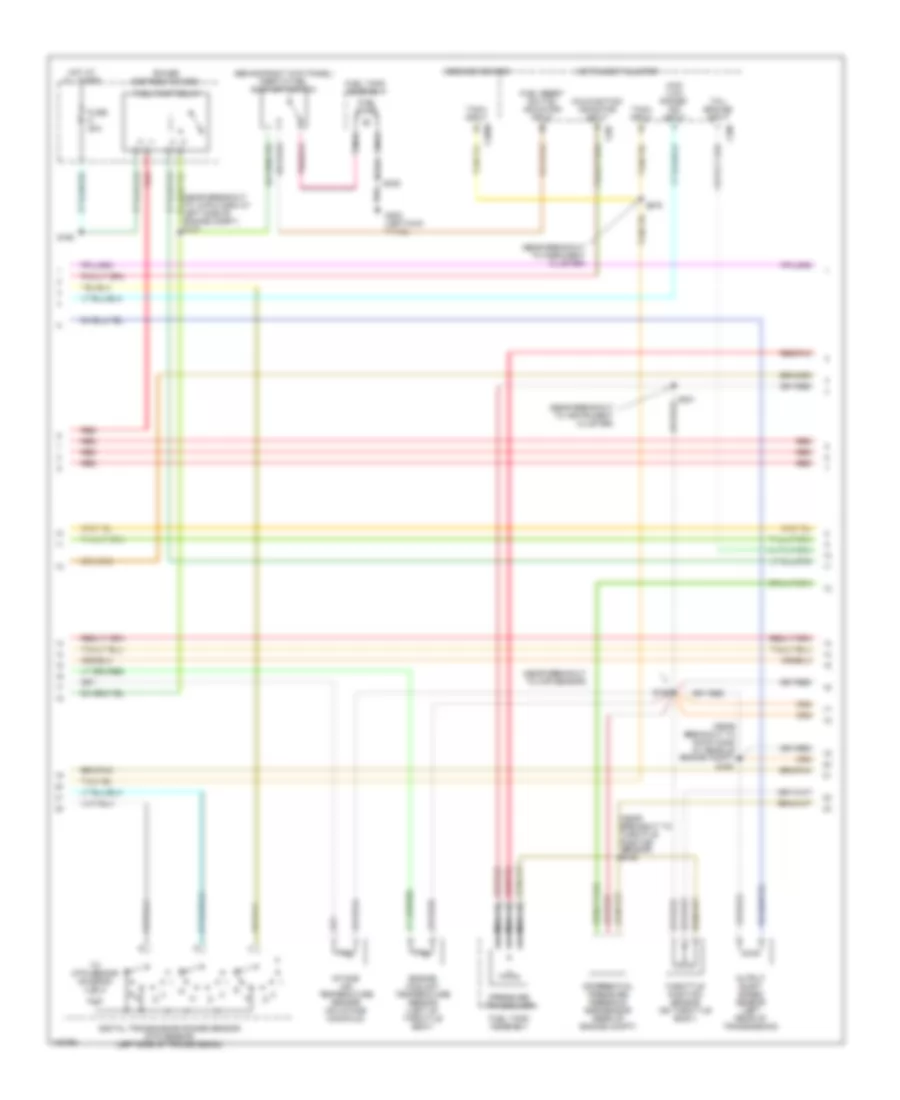
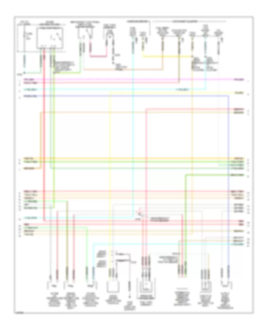
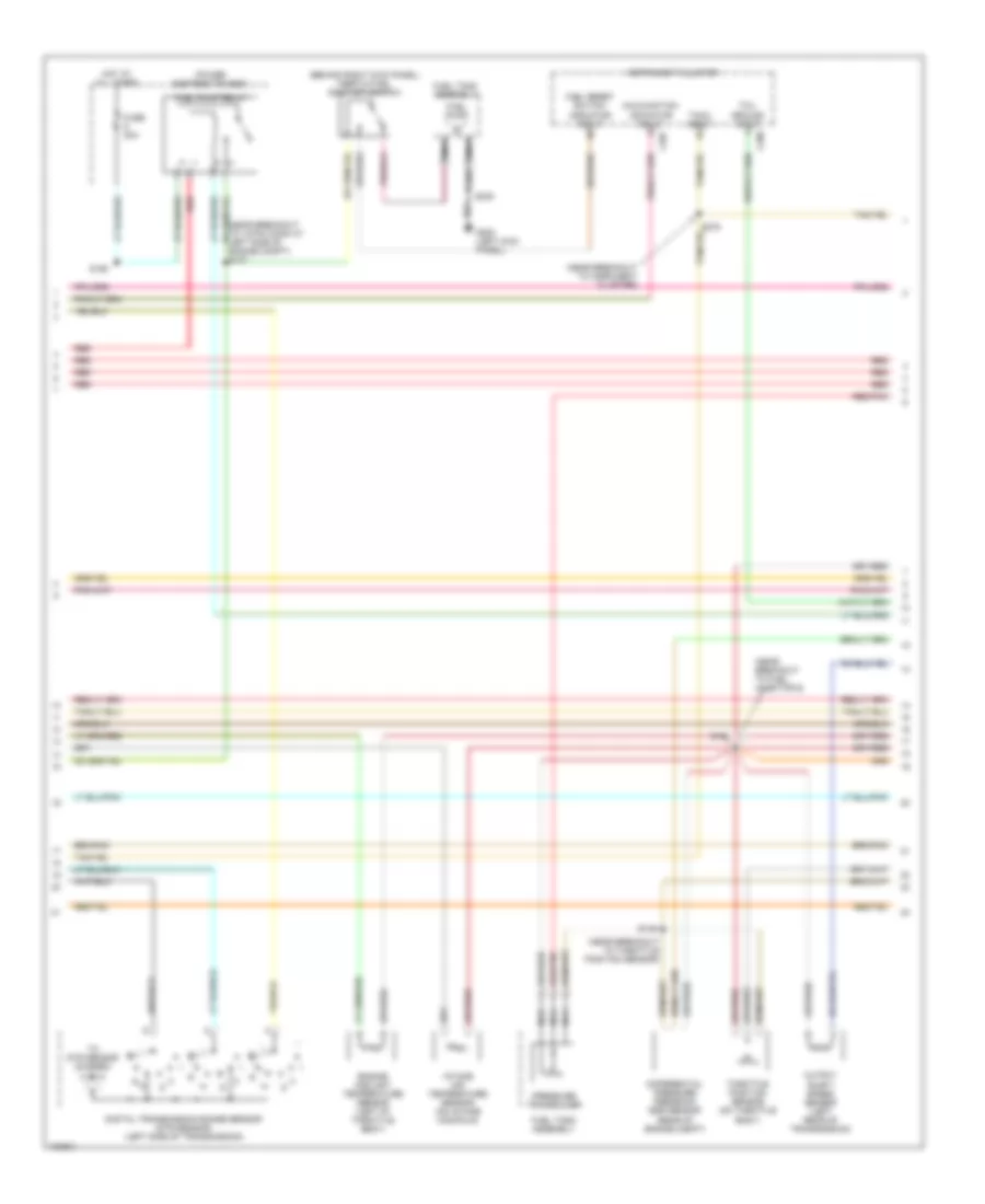
4.0L OHV, Engine Performance Wiring Diagrams (1 of 4) for Ford Explorer 1998
 https://portal-diagnostov.com/license.html
Automotive Electricians Portal FZCO
Automotive Electricians Portal FZCO
https://portal-diagnostov.com/license.html
https://portal-diagnostov.com/license.html
Automotive Electricians Portal FZCO
Automotive Electricians Portal FZCO
List of elements for 4.0L OHV, Engine Performance Wiring Diagrams (1 of 4) for Ford Explorer 1998:
- (behind center
- (left radiator support) g108
- (near breakout to inst cluster)
- (right side of dash) g203
- A/c
- Air conditioning
- Air conditioning system (htr-a/c assy)
- Awd indicator
- C282
- C283
- Case gnd
- Central timer module (ctm)/ generic electronic module (gem)
- Ckp sensor (+)
- Ckp sensor (-)
- Crankshaft position sensor (lower front of engine compt)
- Crankshaft position sensor shield
- Data link
- Data link (+)
- Data link (-)
- Data link connector (behind left side of dash)
- Ect sens
- Evr ctrl
- Fuel level in
- Fuel pump mon
- Fuse 15a
- Fuse 25a
- Fuse 30a
- G108 (left radiator support)
- G203 (right side of dash)
- Gem
- Ho2s 2 sig
- Hot at all times
- Hot in run
- Hot in run or start
- Iat sens
- Ign coil
- Ignition coil (above valve cover)
- Instrument cluster system
- Interior fuse panel
- Maf sig rtn
- Mil
- Of dash)
- Oss
- Pcm power diode
- Pcm power relay
- Power distribution box
- Powertrain control module (mounted through firewall)
- Pwr gnd
- Radio noise capacitor (left of ignition coil)
- Red
- S105
- S108
- S118 (near breakout to fuel injector 3)
- S123 (near breakout to fuel pump relay)
- S205
- S206 (near breakout to ground g901)
- S207
- S248
- Shift sol 1
- Shift sol 2
- Shift sol 4
- Spark plugs
- Tachometer
- Tr1
- Tr2a
- Tr4a
- Trans ctrl sw
- Trans temp
- Transmission control switch
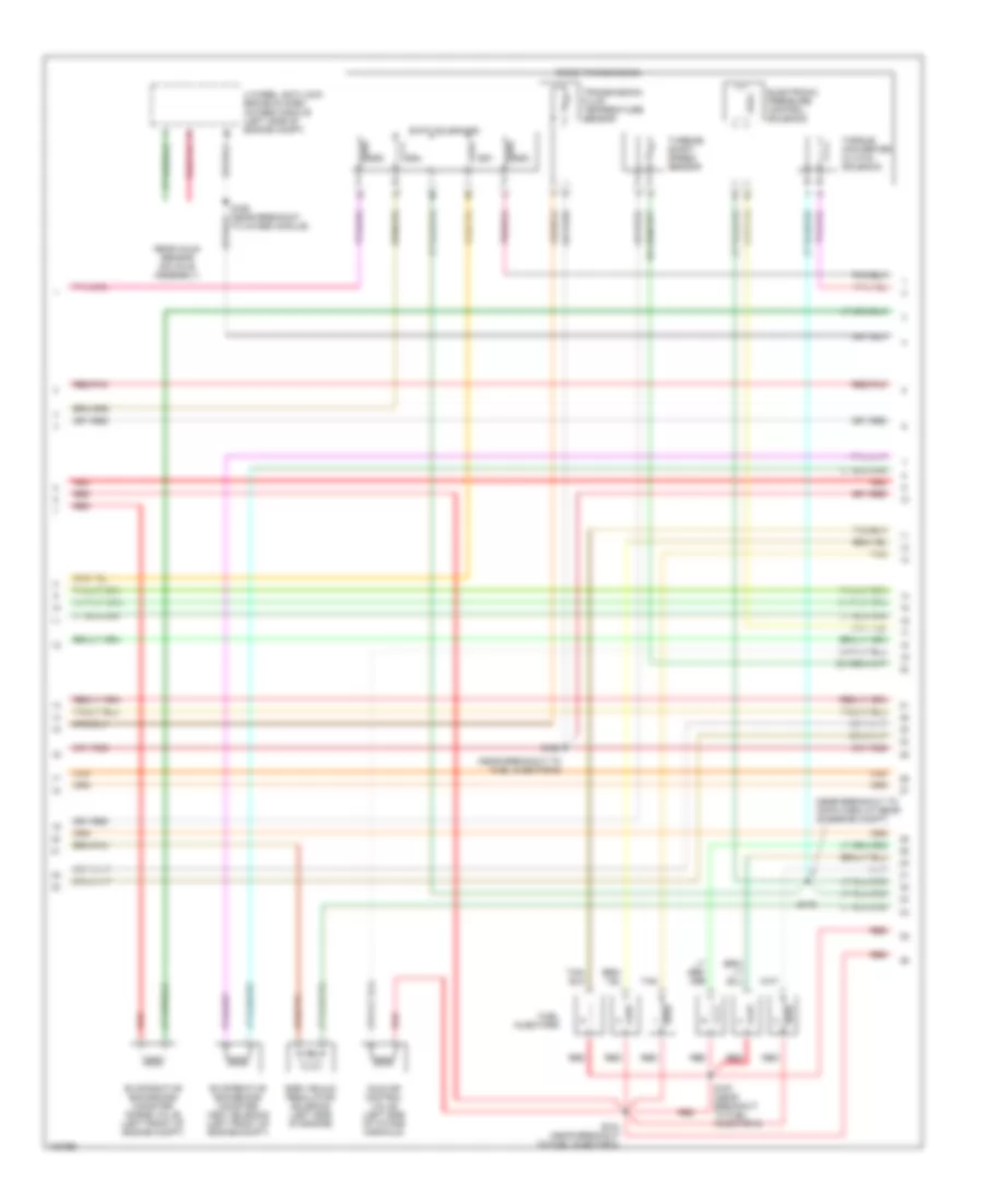
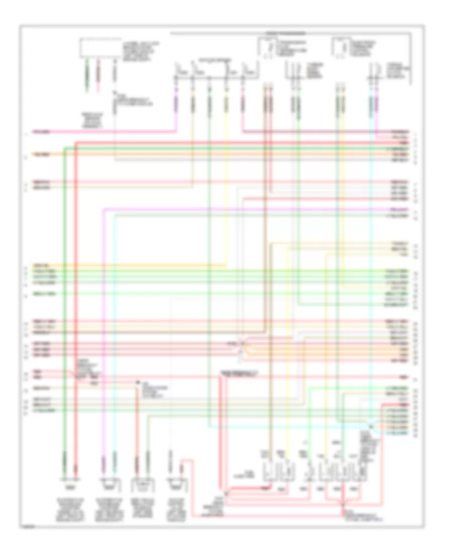
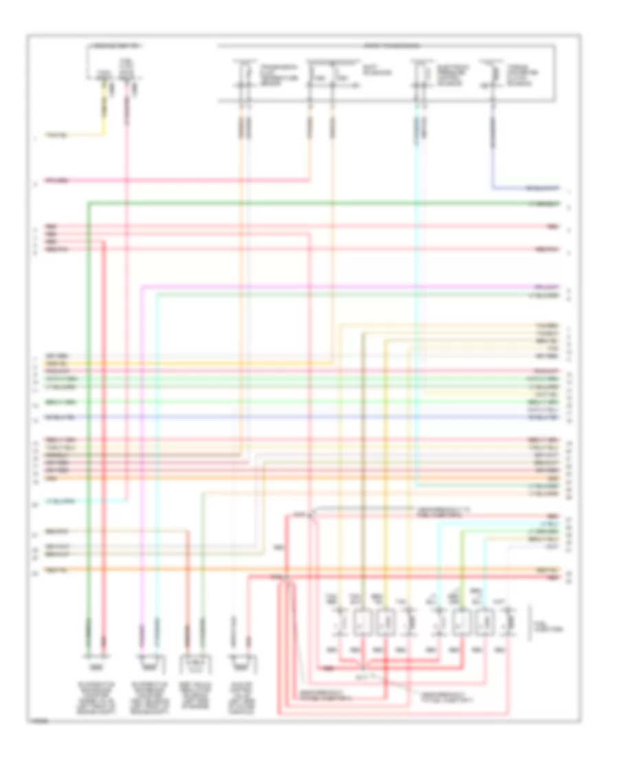
4.0L OHV, Engine Performance Wiring Diagrams (2 of 4) for Ford Explorer 1998
 https://portal-diagnostov.com/license.html
Automotive Electricians Portal FZCO
Automotive Electricians Portal FZCO
https://portal-diagnostov.com/license.html
https://portal-diagnostov.com/license.html
Automotive Electricians Portal FZCO
Automotive Electricians Portal FZCOList of elements for 4.0L OHV, Engine Performance Wiring Diagrams (2 of 4) for Ford Explorer 1998:
- (behind right kick panel) inertia fuel shut-off switch
- (near breakout to 12-pin conn at left side of engine compt) s127
- (near breakout to 16-pin conn at rear of engine compt)
- (near breakout to insrument cluster)
- (near breakout to instrument cluster)
- (near breakout to map sensor)
- (near breakout to throttle position sensor) s146
- 4wd "low range" ind input
- C2009
- C286
- C287
- Differential pressure feedback egr sensor (rear of engine compt)
- Digital transmission range sensor (dtr sensor) (left side of transmission)
- Engine coolant temperature sensor (left of throttle body)
- Fuel pump
- Fuel pump relay
- Fuel reset switch indicator input
- Fuel tank assembly
- Fuse 20a
- G200 (left kick panel)
- Hot at all times
- Instrument cluster
- Intake air temperature sensor (on intake manifold)
- Malfunction indicator input
- Message center
- Nca
- Output shaft speed sensor (left rear of transmission)
- Power distribution box
- Pressure transducer
- R n
- Red
- Red/pnk
- S136
- S160
- S180
- S201
- S235
- S275
- Tach input
- Tcil ground input
- Throttle position sensor (on throttle body)
- To dtr sensor (diagram 4 of 4)
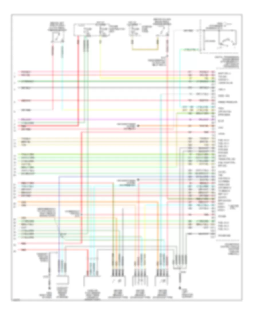
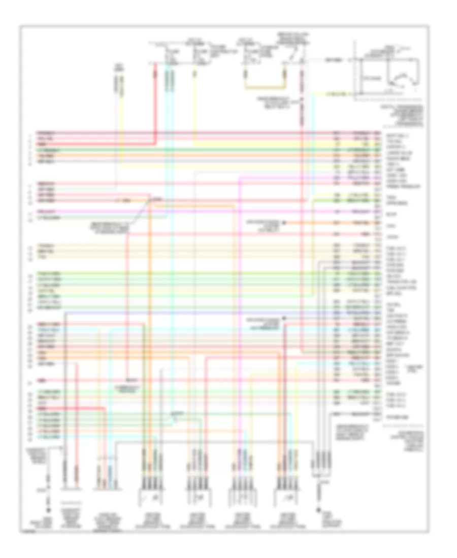
4.0L OHV, Engine Performance Wiring Diagrams (3 of 4) for Ford Explorer 1998
 https://portal-diagnostov.com/license.html
Automotive Electricians Portal FZCO
Automotive Electricians Portal FZCO
https://portal-diagnostov.com/license.html
https://portal-diagnostov.com/license.html
Automotive Electricians Portal FZCO
Automotive Electricians Portal FZCOList of elements for 4.0L OHV, Engine Performance Wiring Diagrams (3 of 4) for Ford Explorer 1998:
- (near breakout to 16-pin conn at rear of engine compt)
- (near breakout to fuel injector 6)
- 4 wheel anti-lock brake system (4wabs) module (left side of engine compt)
- 5r55e transmission
- Egr vacuum regulator solenoid (left side of engine)
- Electronic pressure control solenoid
- Evaporative emmissions canister purge valve (left front of engine compt)
- Evaporative emmissions canister vent solenoid (left front of engine compt)
- Fuel injectors
- Idle air control valve (left side of intake manifold)
- Rear axle sensor (on axle assembly)
- Red
- Red/pnk
- S124 (near breakout to fuel injector 4)
- S166
- S167 (near breakout to fuel injector 6)
- S179
- Shift solenoids
- Ss1
- Ss2
- Ss3
- Ss4
- Tan
- To 4wabs module)
- Torque converter clutch solenoid
- Transmission fluid temperature sensor
- Turbine shaft speed sensor
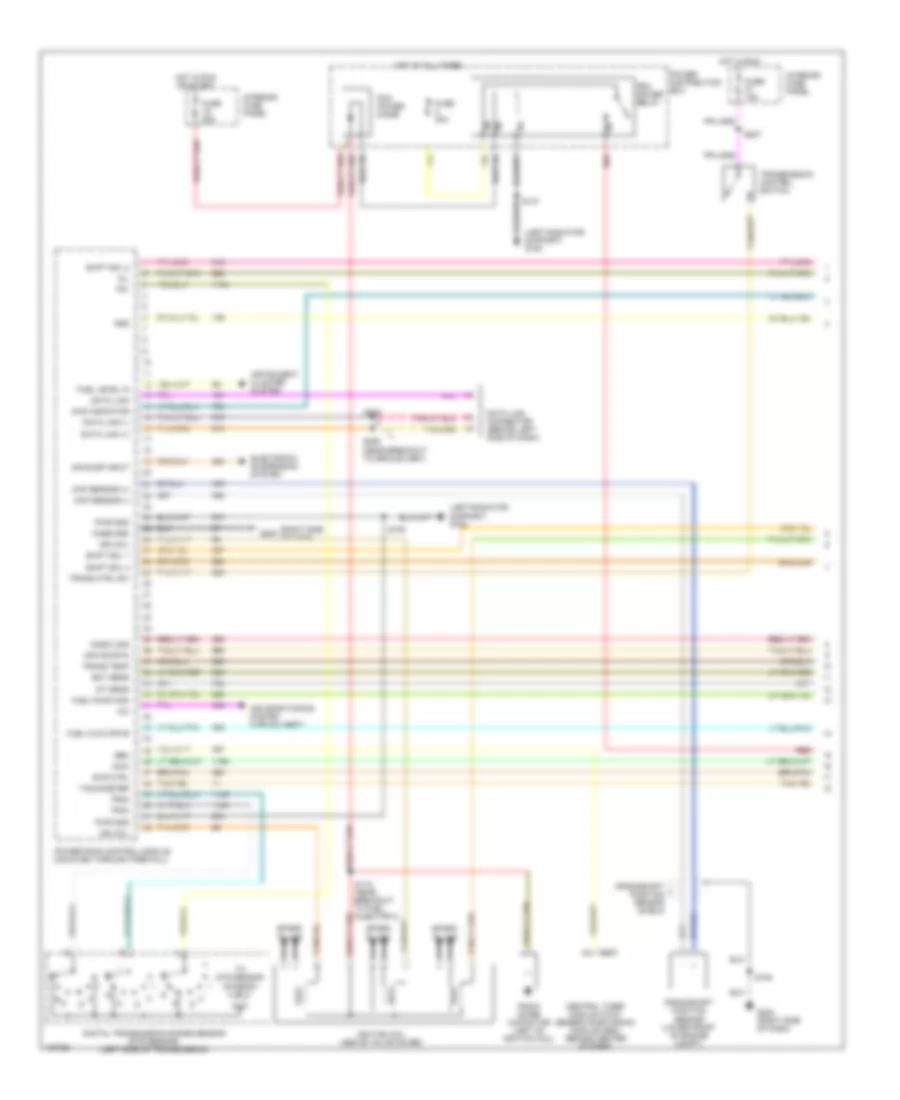
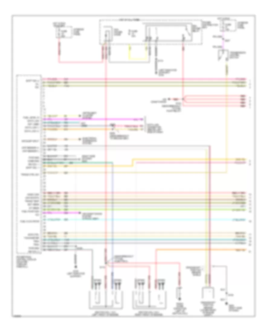
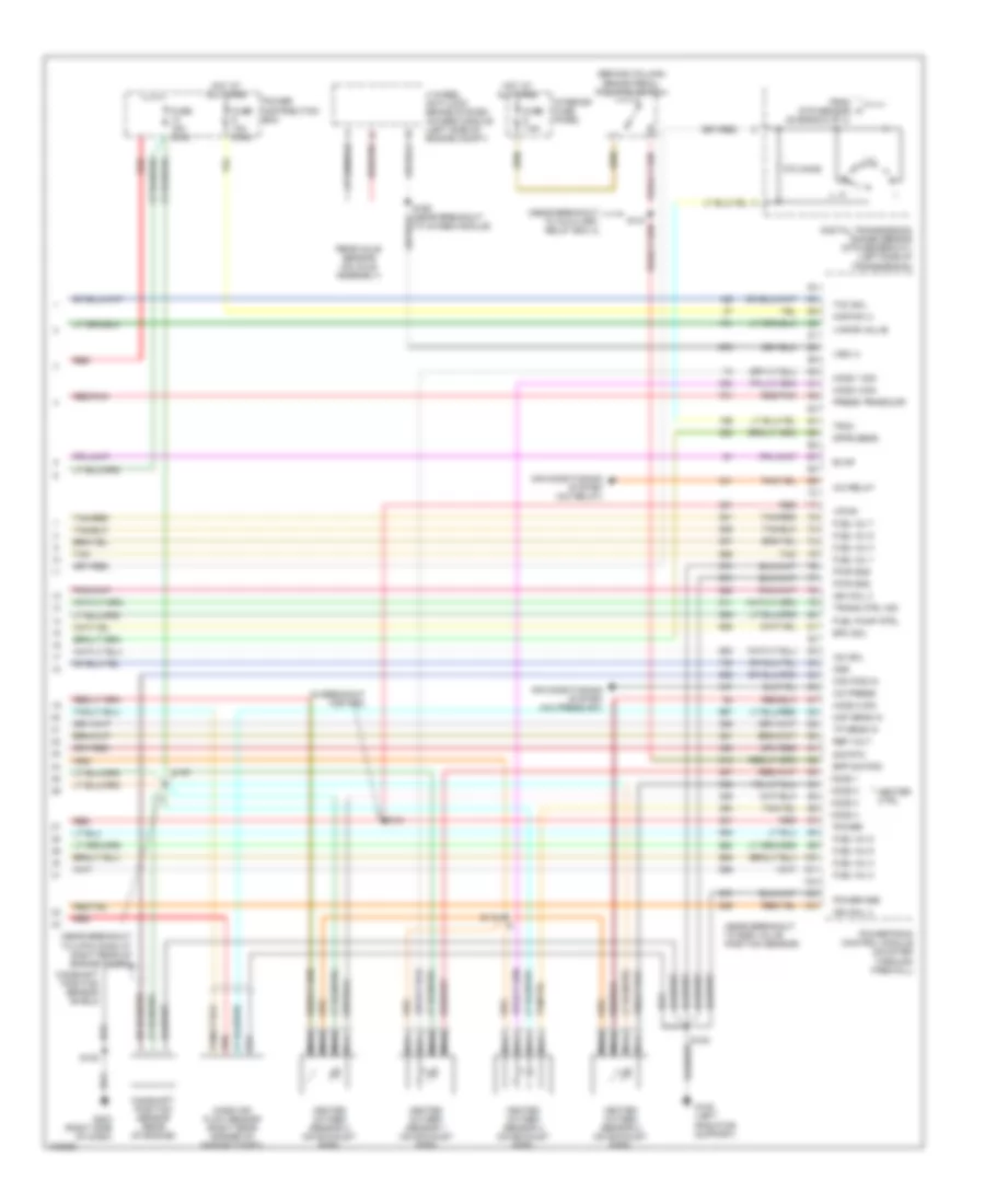
4.0L OHV, Engine Performance Wiring Diagrams (4 of 4) for Ford Explorer 1998
 https://portal-diagnostov.com/license.html
Automotive Electricians Portal FZCO
Automotive Electricians Portal FZCO
https://portal-diagnostov.com/license.html
https://portal-diagnostov.com/license.html
Automotive Electricians Portal FZCO
Automotive Electricians Portal FZCOList of elements for 4.0L OHV, Engine Performance Wiring Diagrams (4 of 4) for Ford Explorer 1998:
- (a/t)
- (behind column) brake pedal position switch
- (behind left side of dash) clutch pedal position switch
- (in breakout for pcm) s101
- (m/t)
- (near breakout to 4-pin conn at right rear of engine compt)
- 270 ohms
- A/c press
- Air conditioning system (a/c press sw)
- Air conditioning system (a/c relay)
- Bpp switch
- Cam pos in
- Camshaft position sensor (rear of engine)
- Camshaft position sensor shield
- Cpp switch
- Digital transmission range sensor (dtr sensor-a/t) (left side of transmission)
- Dpfe sens
- Epc sol
- Evap
- From dtr sensor (diagram 2 of 4)
- Fuel inj 1
- Fuel inj 2
- Fuel inj 3
- Fuel inj 4
- Fuel inj 5
- Fuel inj 6
- Fuel pump ctrl
- Fuse 10a (mini)
- Fuse 15a (mini)
- Fuse 7.5a
- G108 (left radiator support)
- G203 (right side of dash)
- Heated oxygen sensor 1 (on exhaust pipe)
- Heated oxygen sensor 2 (on exhaust pipe)
- Heated oxygen sensor 3 (on exhaust pipe)
- Heater ctrl
- Ho2s 1
- Ho2s 1 sig
- Ho2s 2
- Ho2s 2 sig
- Ho2s 3
- Hot at all times
- Iac sol
- Ign coil
- Interior fuse panel
- Kapwr (+)
- Maf sens in
- Mass air flow sensor (right rear corner of engine compt)
- Nca
- Power
- Power distribution box
- Power gnd
- Powertrain control module (mounted through firewall)
- Press trnsducr
- Pwr gnd
- Red
- Red/pnk
- Ref volt
- S105
- S108
- S142
- S147 (near breakout to auxiliary relay box 3)
- Shift sol 3
- Sig rtn
- Tan
- Tcc sol
- Tp sens in
- Tr3a
- Trans ctrl ind
- Tss
- Vapor valve
- Vpwr
- Vss (+)
- Wac
4.0L SOHC, Engine Performance Wiring Diagrams (1 of 4) for Ford Explorer 1998
 https://portal-diagnostov.com/license.html
Automotive Electricians Portal FZCO
Automotive Electricians Portal FZCO
https://portal-diagnostov.com/license.html
https://portal-diagnostov.com/license.html
Automotive Electricians Portal FZCO
Automotive Electricians Portal FZCOList of elements for 4.0L SOHC, Engine Performance Wiring Diagrams (1 of 4) for Ford Explorer 1998:
- (left radiator support) g108
- (right side of dash)
- A/c
- Air conditioning system (htr-a/c assy)
- Air susp input
- Awd indicator
- C283
- Case gnd
- Central timer module (ctm)/ generic electronic module (gem) (behind center of dash)
- Ckp sensor (+)
- Ckp sensor (-)
- Crankshaft position sensor (lower front of engine compt)
- Crankshaft position sensor shield
- Data link
- Data link (+)
- Data link (-)
- Data link connector (behind left side of dash)
- Digital transmission range sensor (dtr sensor) (left side of transmission)
- Ect sens
- Electronic suspension system
- Evr ctrl
- Fuel flow rate
- Fuel level in
- Fuel pump mon
- Fuse 15a
- Fuse 25a
- Fuse 30a
- G203
- G203 (right side of dash)
- Gem
- Ho2s 2 sig
- Hot at all times
- Hot in run
- Hot in run or start
- Iat sens
- Ign coil
- Ignition coil (above valve cover)
- Imcc
- Instrument cluster system
- Interior fuse panel
- Maf sig rtn
- Mil
- Oss
- Pcm power diode
- Pcm power relay
- Power distribution box
- Powertrain control module (mounted through firewall)
- Pwr gnd
- R n
- Radio noise capacitor (left of ignition coil)
- Red
- S105
- S108
- S118 (near breakout to fuel injector 3)
- S205
- S206 (near breakout to ground g901)
- S207
- Shift sol 1
- Shift sol 2
- Shift sol 4
- Spark plugs
- Tachometer
- To dtr sensor (diagram 4 of 4)
- Tr1
- Tr2a
- Tr4a
- Trans ctrl sw
- Trans temp
- Transmission control switch
4.0L SOHC, Engine Performance Wiring Diagrams (2 of 4) for Ford Explorer 1998
 https://portal-diagnostov.com/license.html
Automotive Electricians Portal FZCO
Automotive Electricians Portal FZCO
https://portal-diagnostov.com/license.html
https://portal-diagnostov.com/license.html
Automotive Electricians Portal FZCO
Automotive Electricians Portal FZCOList of elements for 4.0L SOHC, Engine Performance Wiring Diagrams (2 of 4) for Ford Explorer 1998:
- (behind right kick panel) inertia fuel shut-off switch
- (near breakout to 12-pin conn at left side of engine compt) s127
- (near breakout to instr cluster)
- (near breakout to map sensor)
- (near breakout to throttle position sensor)
- 4wd "low range" ind input
- C2008
- C2009
- Differential pressure feedback egr sensor (rear of engine compt)
- Engine coolant temperature sensor (left of throttle body)
- Fuel flow rate input
- Fuel pump
- Fuel pump relay
- Fuel reset switch indicator input
- Fuel tank assembly
- Fuse 20a
- G108 (left radiator support)
- G200 (left kick panel)
- Hot at all times
- Instrument cluster
- Intake air temperature sensor (on intake manifold)
- Intake manifold communicator control (near intake manifold)
- Knock sensor (near intake manifold)
- Knock sensor shield 1
- Knock sensor shield 2
- Malfunction indicator input
- Message center
- Nca
- Output shaft speed sensor (left rear of transmission)
- Power distribution box
- Pressure transducer
- Red
- Red/pnk
- S105
- S136
- S146
- S160
- S235
- S248
- Tach input
- Tcil ground input
- Throttle position sensor (on throttle body)
4.0L SOHC, Engine Performance Wiring Diagrams (3 of 4) for Ford Explorer 1998
 https://portal-diagnostov.com/license.html
Automotive Electricians Portal FZCO
Automotive Electricians Portal FZCO
https://portal-diagnostov.com/license.html
https://portal-diagnostov.com/license.html
Automotive Electricians Portal FZCO
Automotive Electricians Portal FZCOList of elements for 4.0L SOHC, Engine Performance Wiring Diagrams (3 of 4) for Ford Explorer 1998:
- (near breakout to fuel injector 6)
- (near breakout to fuel pump relay) s123
- 4 wheel anti-lock brake system (4wabs) module (left side of engine compt)
- 5r55e transmission
- Air conditioning system (a/c relay)
- Egr vacuum regulator solenoid (left side of engine)
- Electronic pressure control solenoid
- Evaporative emmissions canister purge valve (left front of engine compt)
- Evaporative emmissions canister vent solenoid (left front of engine compt)
- Fuel injectors
- Idle air control valve (left side of intake manifold)
- Rear axle sensor (on axle assembly)
- Red
- Red/pnk
- S124 (near breakout to fuel injector 4)
- S166
- S167
- Shift solenoids
- Ss1
- Ss2
- Ss3
- Ss4
- Tan
- To 4wabs module)
- Torque converter clutch solenoid
- Transmission fluid temperature sensor
- Turbine shaft speed sensor
4.0L SOHC, Engine Performance Wiring Diagrams (4 of 4) for Ford Explorer 1998
 https://portal-diagnostov.com/license.html
Automotive Electricians Portal FZCO
Automotive Electricians Portal FZCO
https://portal-diagnostov.com/license.html
https://portal-diagnostov.com/license.html
Automotive Electricians Portal FZCO
Automotive Electricians Portal FZCOList of elements for 4.0L SOHC, Engine Performance Wiring Diagrams (4 of 4) for Ford Explorer 1998:
- (behind column) brake pedal position switch
- (in breakout for pcm)
- (near breakout to 16-pin conn at rear of engine compt)
- (near breakout to 4-pin conn at right rear of engine compt)
- (near breakout to auxiliary relay box 3)
- 270 ohms
- A/c press
- Air conditioning system (a/c press sw)
- Air conditioning system (a/c relay)
- Bpp switch
- Cam pos in
- Camshaft position sensor (rear of engine)
- Camshaft position sensor shield
- Digital transmission range sensor (dtr sensor-a/t) (left side of transmission)
- Dpfe sens
- Epc sol
- Evap
- From dtr sensor (diagram 1 of 4)
- Fuel inj 1
- Fuel inj 2
- Fuel inj 3
- Fuel inj 4
- Fuel inj 5
- Fuel inj 6
- Fuel pump ctrl
- Fuse 10a (mini)
- Fuse 15a (mini)
- Fuse 7.5a
- G108 (left radiator support)
- G203 (right side of dash)
- Heated oxygen sensor 1 (on exhaust pipe)
- Heated oxygen sensor 2 (on exhaust pipe)
- Heated oxygen sensor 3 (on exhaust pipe)
- Heated oxygen sensor 4 (on exhaust pipe)
- Heater ctrl
- Ho2s 1
- Ho2s 1 sig
- Ho2s 2
- Ho2s 2 sig
- Ho2s 3
- Ho2s 4
- Ho2s 4 sig
- Hot at all times
- Iac sol
- Ign coil
- Interior fuse panel
- Kapwr (+)
- Knock sens
- Maf sens in
- Mass air flow sensor (right rear corner of engine compt)
- Nca
- Not used
- Power
- Power distribution box
- Power gnd
- Powertrain control module (mounted through firewall)
- Press trnsducr
- Pwr gnd
- Red
- Red/pnk
- Ref volt
- S101
- S105
- S108
- S142
- S180
- Shift sol 3
- Sig rtn
- Tan
- Tcc sol
- Tp sens in
- Tr3a
- Trans ctrl ind
- Tss
- Vapor valve
- Vpwr
- Vss (+)
- Wac
5.0L
5.0L, Engine Performance Wiring Diagrams (1 of 4) for Ford Explorer 1998
 https://portal-diagnostov.com/license.html
Automotive Electricians Portal FZCO
Automotive Electricians Portal FZCO
https://portal-diagnostov.com/license.html
https://portal-diagnostov.com/license.html
Automotive Electricians Portal FZCO
Automotive Electricians Portal FZCOList of elements for 5.0L, Engine Performance Wiring Diagrams (1 of 4) for Ford Explorer 1998:
- (left radiator support) g108
- (near breakout to fuel injector 3)
- (right side of dash) g203
- A/c
- Air conditioning
- Air conditioning system (htr-a/c assy)
- Air susp input
- Case gnd
- Ckp sensor (+)
- Ckp sensor (-)
- Crankshaft position sensor (lower front of engine compt)
- Crankshaft position sensor shield
- Data link
- Data link (+)
- Data link (-)
- Data link connector (behind left side of dash)
- Ect sens
- Electronic suspension system
- Evr ctrl
- Fuel flow rate
- Fuel level in
- Fuel pump mon
- Fuse 15a
- Fuse 25a
- Fuse 30a
- G108 (left radiator support)
- G203 (right side of dash)
- Ho2s 2 sig
- Hot at all times
- Hot in run
- Hot in run or start
- Iat sens
- Ign coil 1
- Ign coil 2
- Ignition coil 1 & 2 (left front of engine)
- Ignition coil 3 & 4 (right front of engine)
- Instrument cluster system
- Interior fuse panel
- Maf sig rtn
- Mil
- Not used
- Pcm power diode
- Pcm power relay
- Power distribution box
- Powertrain control module (mounted through firewall)
- Pwr gnd
- Radio noise capacitor (left of ignition coil)
- Red
- S105
- S108
- S118
- S123 (near breakout to fuel pump relay)
- S205
- S206 (near breakout to ground g901)
- S207
- Shift sol 1
- Shift sol 2
- Spark plugs
- Tachometer
- Tr1
- Tr2a
- Tr4a
- Trans ctrl sw
- Trans temp
- Transmission control switch
5.0L, Engine Performance Wiring Diagrams (2 of 4) for Ford Explorer 1998
 https://portal-diagnostov.com/license.html
Automotive Electricians Portal FZCO
Automotive Electricians Portal FZCO
https://portal-diagnostov.com/license.html
https://portal-diagnostov.com/license.html
Automotive Electricians Portal FZCO
Automotive Electricians Portal FZCOList of elements for 5.0L, Engine Performance Wiring Diagrams (2 of 4) for Ford Explorer 1998:
- (behind right kick panel) inertia fuel shut-off switch
- (near breakout to 12-pin conn at left side of engine compt) s127
- (near breakout to fuel injector 6)
- (near breakout to insrument cluster)
- (near breakout to throttle position sensor)
- C286
- C287
- Differential pressure feedback egr sensor (rear of engine compt)
- Digital transmission range sensor (dtr sensor) (left side of transmission)
- Engine coolant temperature sensor (left of throttle body)
- Fuel pump
- Fuel pump relay
- Fuel reset switch indicator input
- Fuel tank assembly
- Fuse 20a
- G200 (left kick panel)
- Hot at all times
- Instrument cluster
- Intake air temperature sensor (on intake manifold)
- Malfunction indicator input
- Nca
- Output shaft speed sensor (left rear of transmission)
- Power distribution box
- Pressure transducer
- R n
- Red
- Red/pnk
- S146
- S160
- S166
- S235
- Tach input
- Tcil ground input
- Throttle position sensor (on throttle body)
- To dtr sensor (diagram 4 of 4)
5.0L, Engine Performance Wiring Diagrams (3 of 4) for Ford Explorer 1998
 https://portal-diagnostov.com/license.html
Automotive Electricians Portal FZCO
Automotive Electricians Portal FZCO
https://portal-diagnostov.com/license.html
https://portal-diagnostov.com/license.html
Automotive Electricians Portal FZCO
Automotive Electricians Portal FZCOList of elements for 5.0L, Engine Performance Wiring Diagrams (3 of 4) for Ford Explorer 1998:
- (near breakout to fuel injector 4)
- (near breakout to fuel injector 6)
- (near breakout to fuel injector 7)
- 4r7ow transmission
- C2008
- C2009
- Egr vacuum regulator solenoid (left side of engine)
- Electronic pressure control solenoid
- Evaporative emmissions canister purge valve (left front of engine compt)
- Evaporative emmissions canister vent solenoid (left front of engine compt)
- Fuel flow rate input
- Fuel injectors
- Idle air control valve (left side of intake manifold)
- Message center
- Red
- Red/pnk
- S117
- S124
- S167
- Shift solenoids
- Ss1
- Ss2
- Tach input
- Tan
- Tan/ red
- Tan/red
- Torque converter clutch solenoid
- Transmission fluid temperature sensor
5.0L, Engine Performance Wiring Diagrams (4 of 4) for Ford Explorer 1998
 https://portal-diagnostov.com/license.html
Automotive Electricians Portal FZCO
Automotive Electricians Portal FZCO
https://portal-diagnostov.com/license.html
https://portal-diagnostov.com/license.html
Automotive Electricians Portal FZCO
Automotive Electricians Portal FZCOList of elements for 5.0L, Engine Performance Wiring Diagrams (4 of 4) for Ford Explorer 1998:
- (behind column) brake pedal position switch
- (in breakout for pcm)
- (near breakout to 4-pin conn at right rear of engine compt)
- (near breakout to auxiliary relay box 3)
- (near breakout to egr valve position sensor)
- 270 ohms
- 4 wheel anti-lock brake system (4wabs) module (left side of engine compt)
- A/c press
- A/c relay
- Air conditioning system (a/c press sw)
- Air conditioning system (a/c relay)
- Bpp switch
- Cam pos in
- Camshaft position sensor (rear of engine)
- Camshaft position sensor shield
- Digital transmission range sensor (dtr sensor-a/t) (left side of transmission)
- Dpfe sens
- Epc sol
- Evap
- From dtr sensor (diagram 2 of 4)
- Fuel inj 1
- Fuel inj 2
- Fuel inj 3
- Fuel inj 4
- Fuel inj 5
- Fuel inj 6
- Fuel inj 7
- Fuel inj 8
- Fuel pump ctrl
- Fuse 10a (mini)
- Fuse 15a (mini)
- Fuse 7.5a
- G108 (left radiator support)
- G203 (right side of dash)
- Heated oxygen sensor 1 (on exhaust pipe)
- Heated oxygen sensor 2 (on exhaust pipe)
- Heated oxygen sensor 3 (on exhaust pipe)
- Heated oxygen sensor 4 (on exhaust pipe)
- Heater ctrl
- Ho2s 1
- Ho2s 1 sig
- Ho2s 2
- Ho2s 2 sig
- Ho2s 3
- Ho2s 4
- Ho2s 4 sig
- Hot at all times
- Iac sol
- Ign coil 3
- Ign coil 4
- Interior fuse panel
- Kapwr (+)
- Maf sens in
- Mass air flow sensor (right rear corner of engine compt)
- Nca
- Oss
- Power
- Power distribution box
- Power gnd
- Powertrain control module (mounted through firewall)
- Press trnsducr
- Pwr gnd
- Rear axle sensor (on axle assembly)
- Red
- Red/pnk
- Ref volt
- S101
- S105
- S108
- S119
- S142
- Sig rtn
- Tan
- Tan/red
- Tcc sol
- To 4wabs module)
- Tp sens in
- Tr3a
- Trans ctrl ind
- Vapor valve
- Vpwr
- Vss (+)

 Čeština
 Dansk
Dansk Deutsch
 Ελληνικά
 English
 English
 Español
 Suomi
Suomi Français
 Français
 עברית
עברית Hrvatski
 Magyar
 Italiano
 日本語
日本語 한국어
한국어 Nederlands
 Polski
 Português
 Português
 Română
 Русский
 Slovenčina
 Slovenščina
 Svenska
 Türkçe
