ENGINE PERFORMANCE
2.0L TURBO
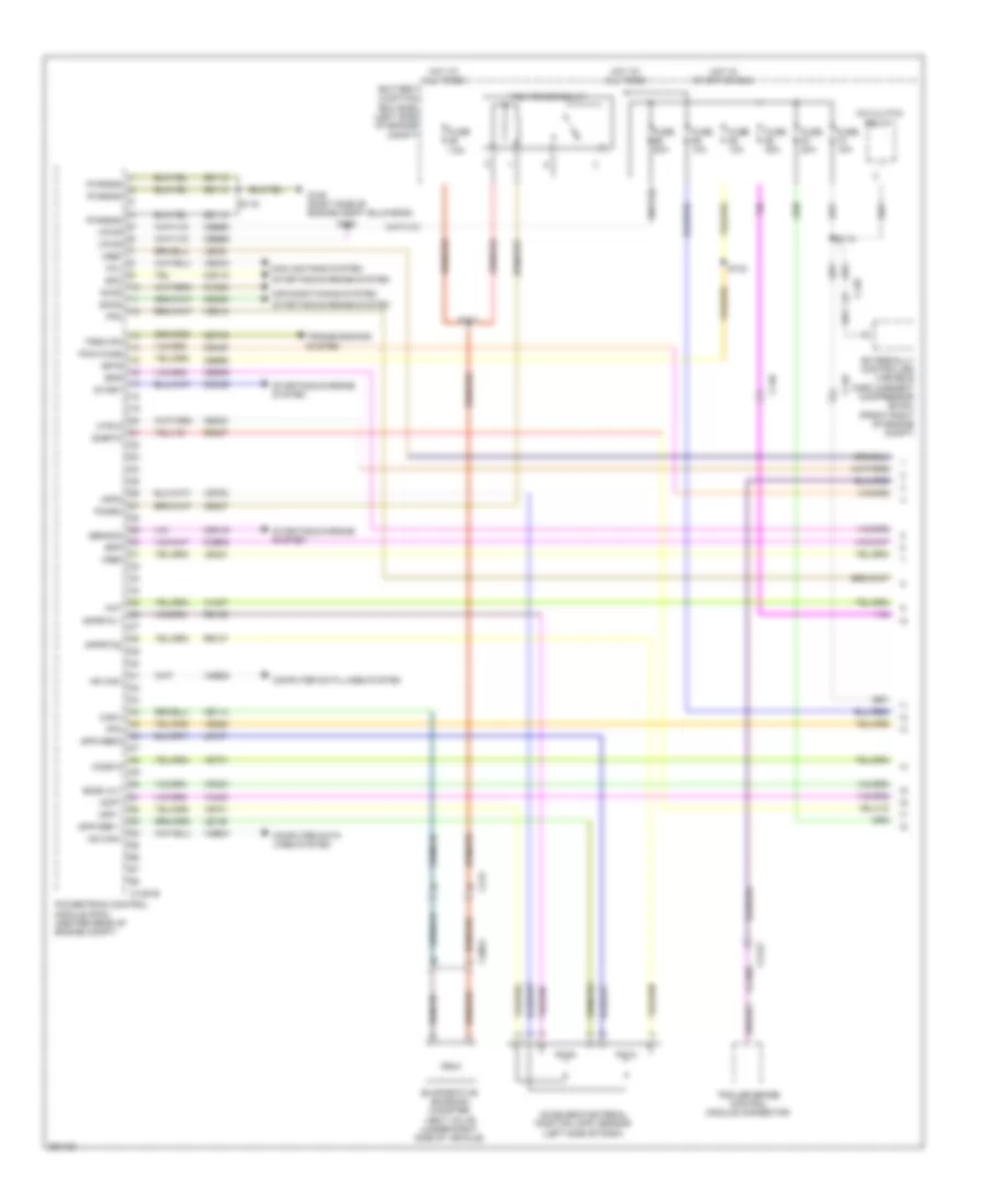
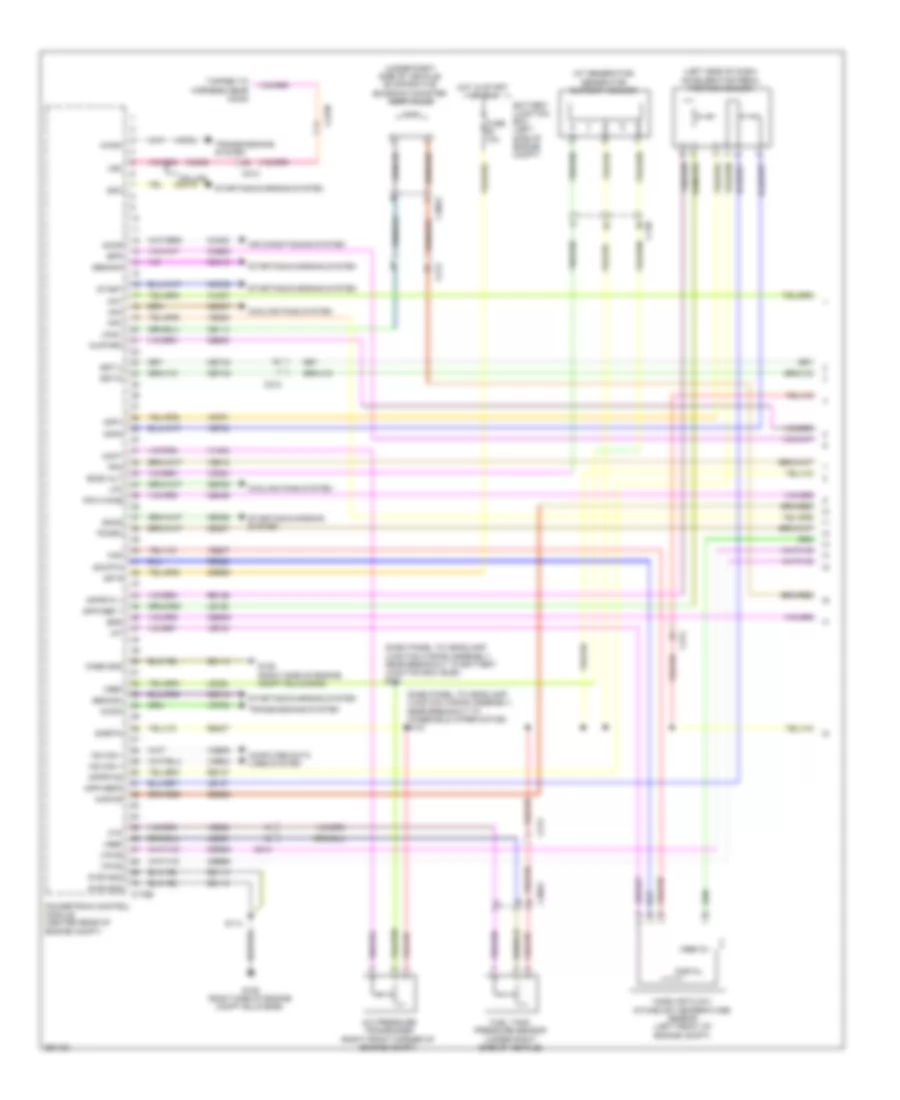
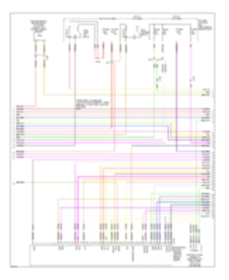
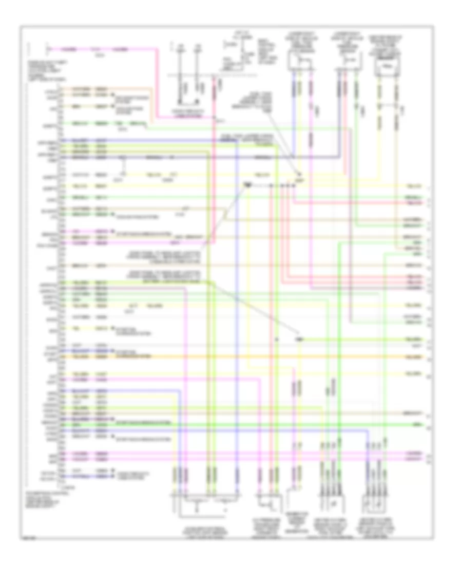
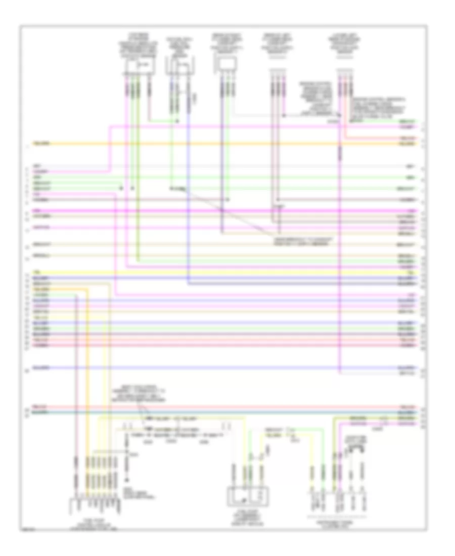
2.0L Turbo, Engine Performance Wiring Diagram (1 of 6) for Ford Explorer 2013
 https://portal-diagnostov.com/license.html
Automotive Electricians Portal FZCO
Automotive Electricians Portal FZCO
https://portal-diagnostov.com/license.html
https://portal-diagnostov.com/license.html
Automotive Electricians Portal FZCO
Automotive Electricians Portal FZCO
List of elements for 2.0L Turbo, Engine Performance Wiring Diagram (1 of 6) for Ford Explorer 2013:
- 7.5a
- A/c clutch relay
- Aat
- Accelerator pedal position (app) sensor (left side of dash)
- Accr
- Acpt
- Air conditioning system
- App 1
- App2
- Apprtn 1
- Apprtn2
- Appvref 1
- Appvref2
- Battery junction box (bjb) (left side of engine compt)
- Bcs2 alt
- Bpp
- Bps
- C1381b
- C139
- C140
- C213
- C2142
- C3053
- Canv
- Cbb69
- Cbb90
- Ccb08
- Cdc12
- Cdc15
- Cdc35
- Ce114
- Ce233
- Ce237
- Ce336
- Ce436
- Ces09
- Cet40
- Ch302
- Computer data lines system
- Cooling fans system
- Evaporative emission canister vent valve (under right side of vehicle)
- Externally controlled variable displacement compressor (evdc) (front right of engine compt)
- Fcv
- Fpc
- Fpm
- Fuse
- Fuse 10a
- Fuse 20a
- G106 (right side of engine compt bulkhead)
- Gd113
- Genmon
- Ho2s12
- Hot at all times
- Hot in start or run
- Hs can+
- Hs can-
- Htr12
- Isp-r
- Le136
- Le137
- Le230
- Le424
- Pcm power relay
- Pcm-wake
- Pcmrc
- Powertrain control module (pcm) (center rear of engine compt)
- Pwrgnd
- Re136
- Re137
- Re407
- S113
- S115
- S116
- S117
- S132
- Sigrtn
- Smc
- Smcs
- Start
- Starting/charging system
- Trailer brake control module connector
- Transmissions system
- Trsw-pn
- Vdb04
- Vdb05
- Vdc61
- Ve225
- Ve518
- Ve701
- Ve702
- Ve731
- Vec03
- Vh407
- Vh433
- Vpwr
- Vref
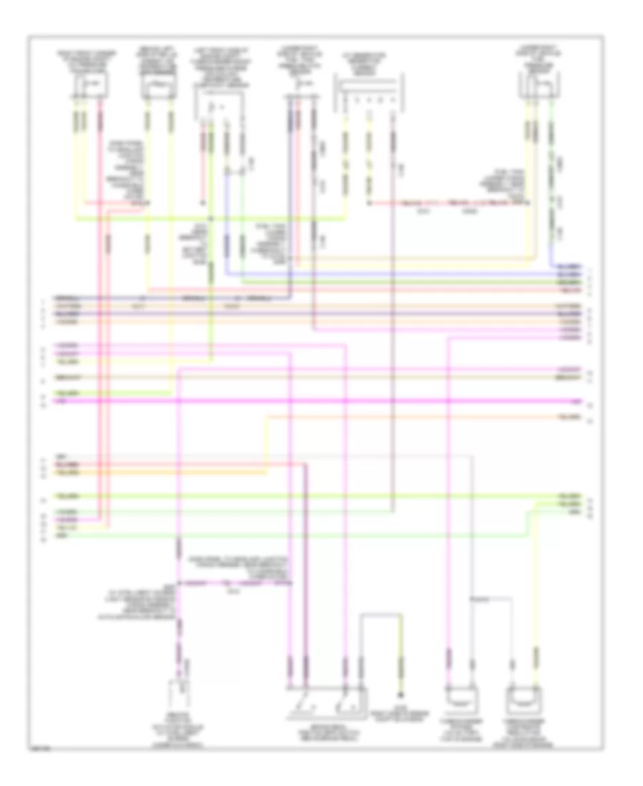
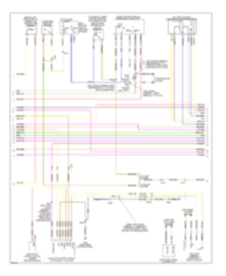
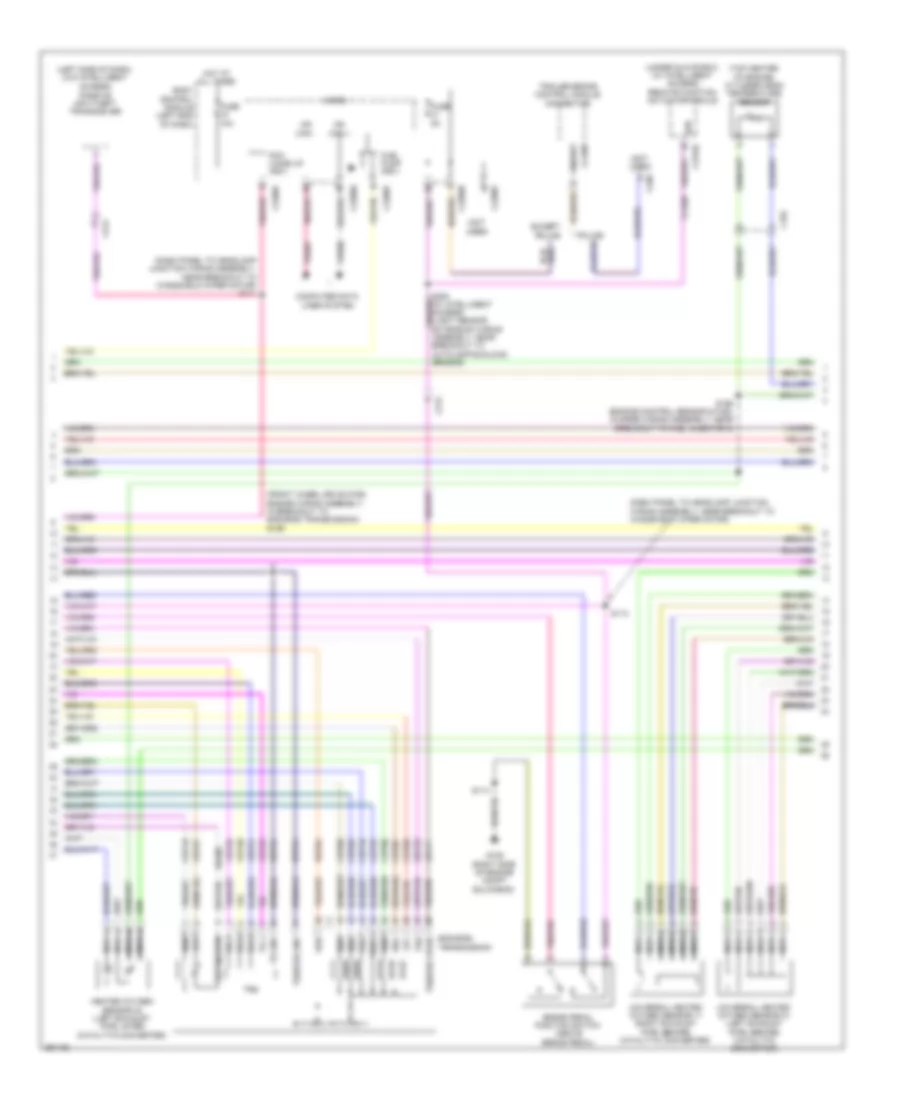
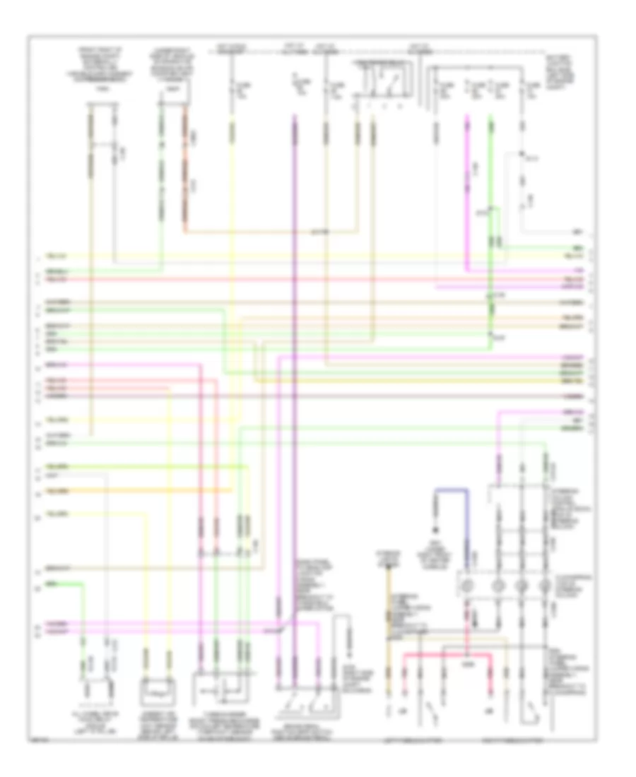
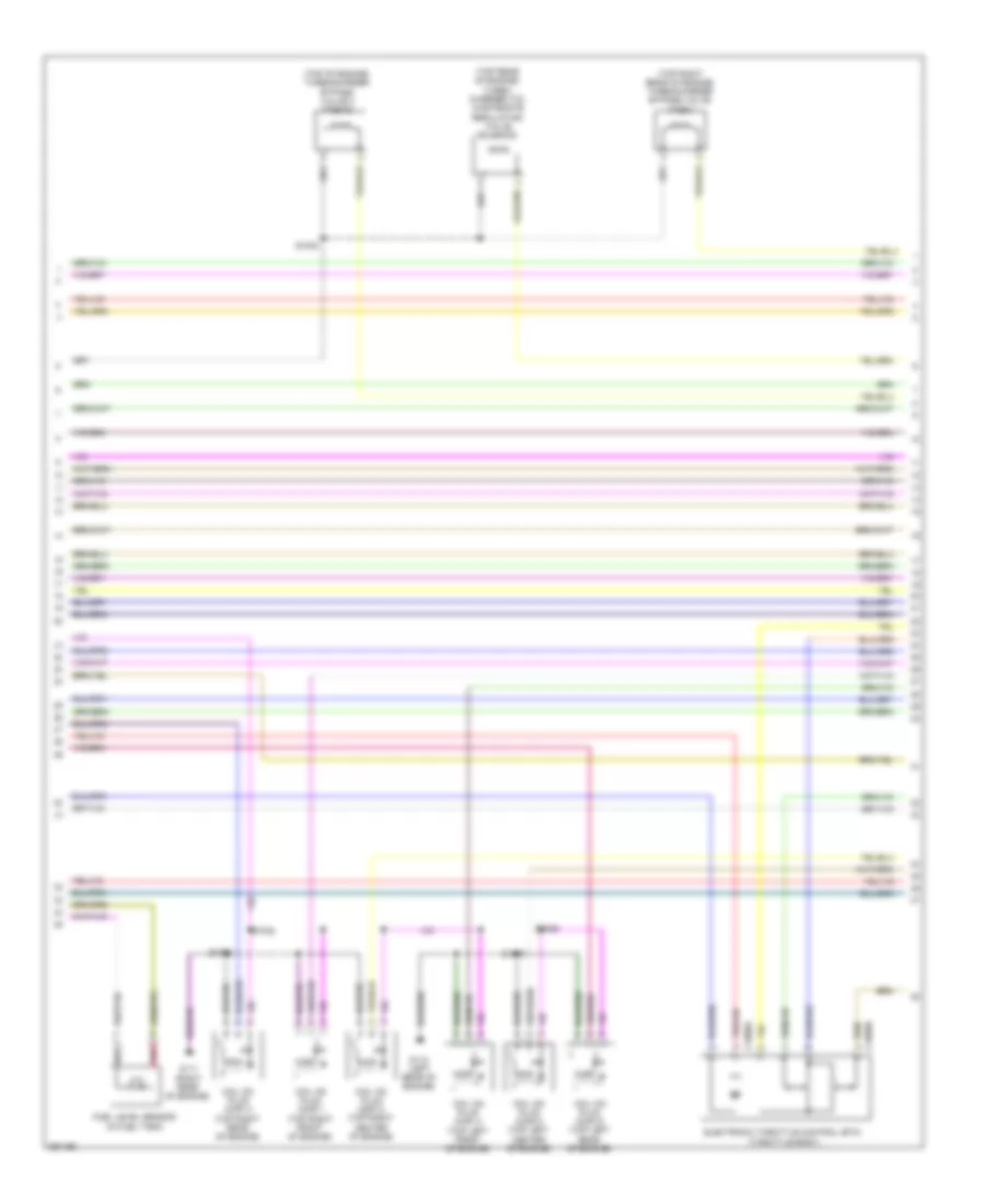
2.0L Turbo, Engine Performance Wiring Diagram (2 of 6) for Ford Explorer 2013
 https://portal-diagnostov.com/license.html
Automotive Electricians Portal FZCO
Automotive Electricians Portal FZCO
https://portal-diagnostov.com/license.html
https://portal-diagnostov.com/license.html
Automotive Electricians Portal FZCO
Automotive Electricians Portal FZCOList of elements for 2.0L Turbo, Engine Performance Wiring Diagram (2 of 6) for Ford Explorer 2013:
- (at generator) generator current sensor
- (behind left side of grille) ambient air temperature (aat) sensor
- (dash panel to headlamp junction wiring assembly, near breakout to windshield wiper motor) s143
- (dash panel to headlamp junction wiring harness, near breakout to windshield wiper motor) s112
- (fuel tank jumper wiring assembly, in breakout to c3123) s398
- (fuel tank jumper wiring assembly, near breakout to c3270) s397
- (left front side of engine compt) turbocharger boost pressure/charge air coolant temperature (tcbp/cact) sensor
- (right front corner of engine compt) a/c pressure transducer
- (under right side of vehicle) fuel pressure sensor
- (under right side of vehicle) fuel tank pressure (ftp) sensor
- Bpp
- Brake pedal position (bpp) switch (above brake pedal)
- C139
- C140
- C212
- C213
- C2153c
- C3053
- Ccb08
- G106 (right side of engine compt bulkhead)
- Remote function actuator module (w/ intelligent access) (under glove box)
- S172
- S200 (w/ intelligent access) (light sensor extension wiring assembly, near breakout to autolamp/sunload sensor)
- Turbocharger bypass valve (tcby) (top of engine)
- Turbocharger wastegate regulating valve solenoid (right side of engine)
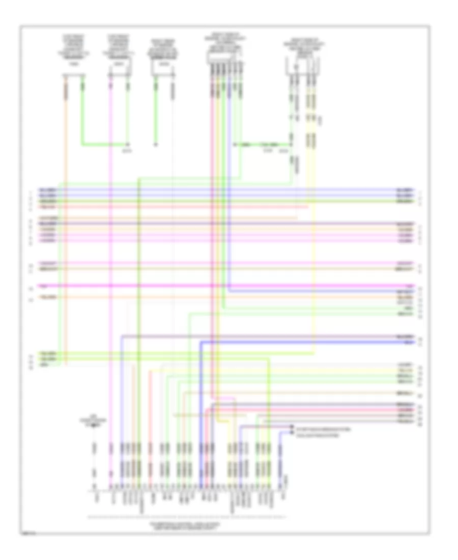
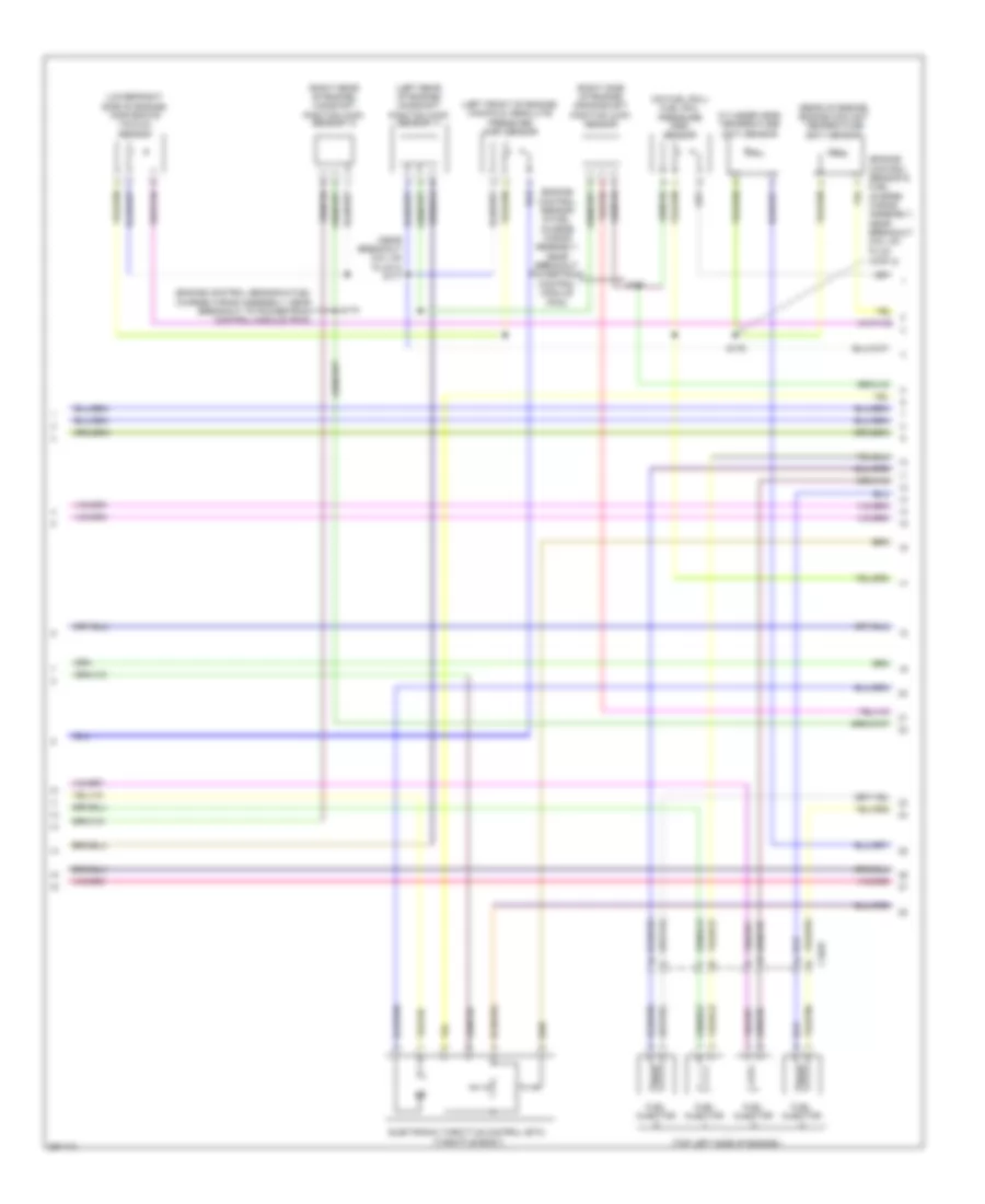
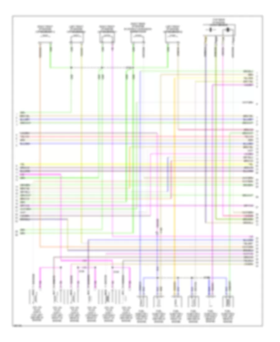
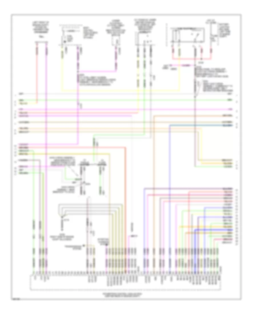
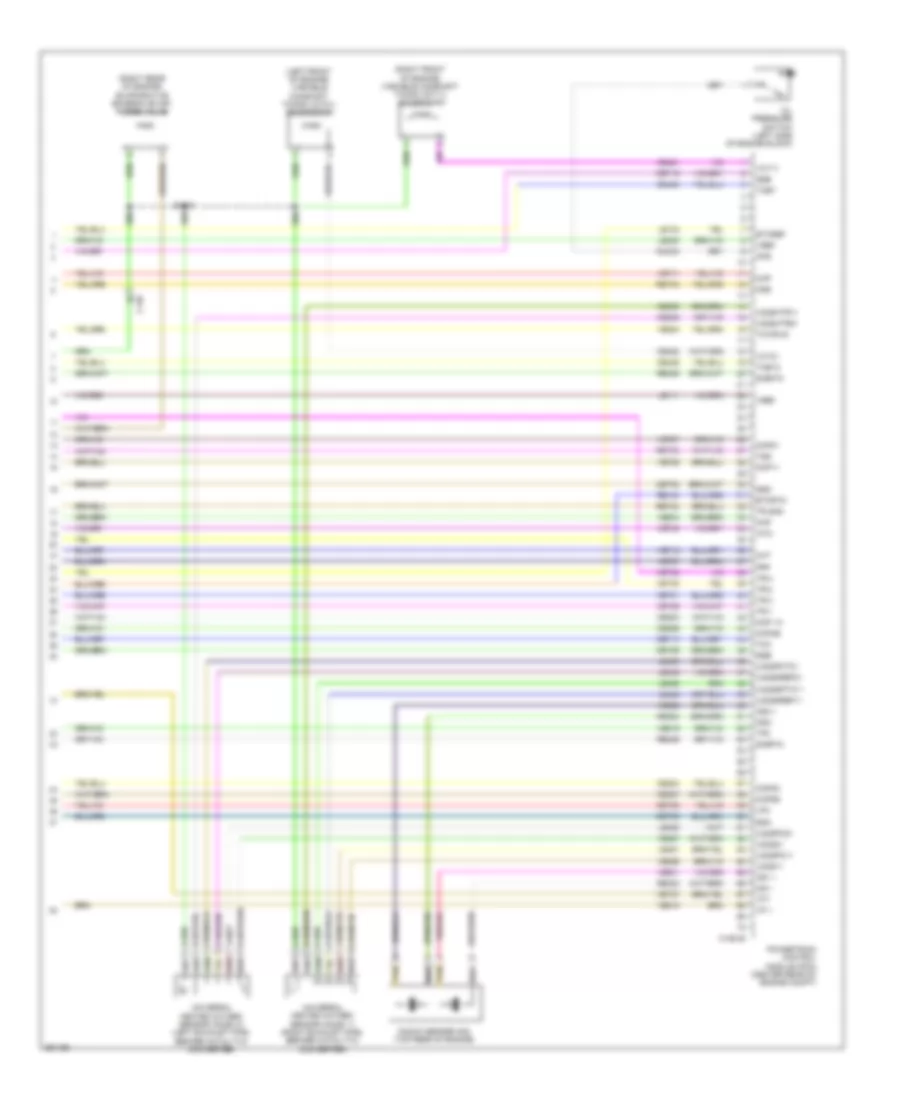
2.0L Turbo, Engine Performance Wiring Diagram (3 of 6) for Ford Explorer 2013
 https://portal-diagnostov.com/license.html
Automotive Electricians Portal FZCO
Automotive Electricians Portal FZCO
https://portal-diagnostov.com/license.html
https://portal-diagnostov.com/license.html
Automotive Electricians Portal FZCO
Automotive Electricians Portal FZCOList of elements for 2.0L Turbo, Engine Performance Wiring Diagram (3 of 6) for Ford Explorer 2013:
- (right rear of engine) evaporative emission (evap) purge valve
- (right side of engine, on exhaust) heated oxygen sensor (ho2s) 12
- (right side of engine, on exhaust) universal heated oxygen sensor (ho2s) 11
- (top front of engine) variable camshaft timing 11 (vct11) solenoid
- (top front of engine) variable camshaft timing 12 (vct12) solenoid
- Air conditioning system
- C1381e
- C139
- C140
- Cdc10
- Ce113
- Ce205
- Ce207
- Ce235
- Ce303
- Ce304
- Ce305
- Ce306
- Ce412
- Ce421
- Ce422
- Cec01
- Cmp11
- Cmp12
- Cooling fans system
- Cop1a
- Cop2d
- Cop3b
- Cop4c
- Evapcp
- Gencom
- Hfc
- Inj1
- Inj3
- Ks1+
- Ks2+
- Le329
- Le451
- Map
- Nca
- Powertrain control module (pcm) (center rear of engine compt)
- S134
- S173
- Starting/charging system
- Tacm+
- Tcwrvs
- Tp2
- Uo2s11
- Uo2shrt11
- Uo2spct11
- Vacc
- Vct11
- Vct12
- Ve462
- Ve706
- Ve707
- Ve801
- Ve802
- Ve819
- Ve824
- Ve826
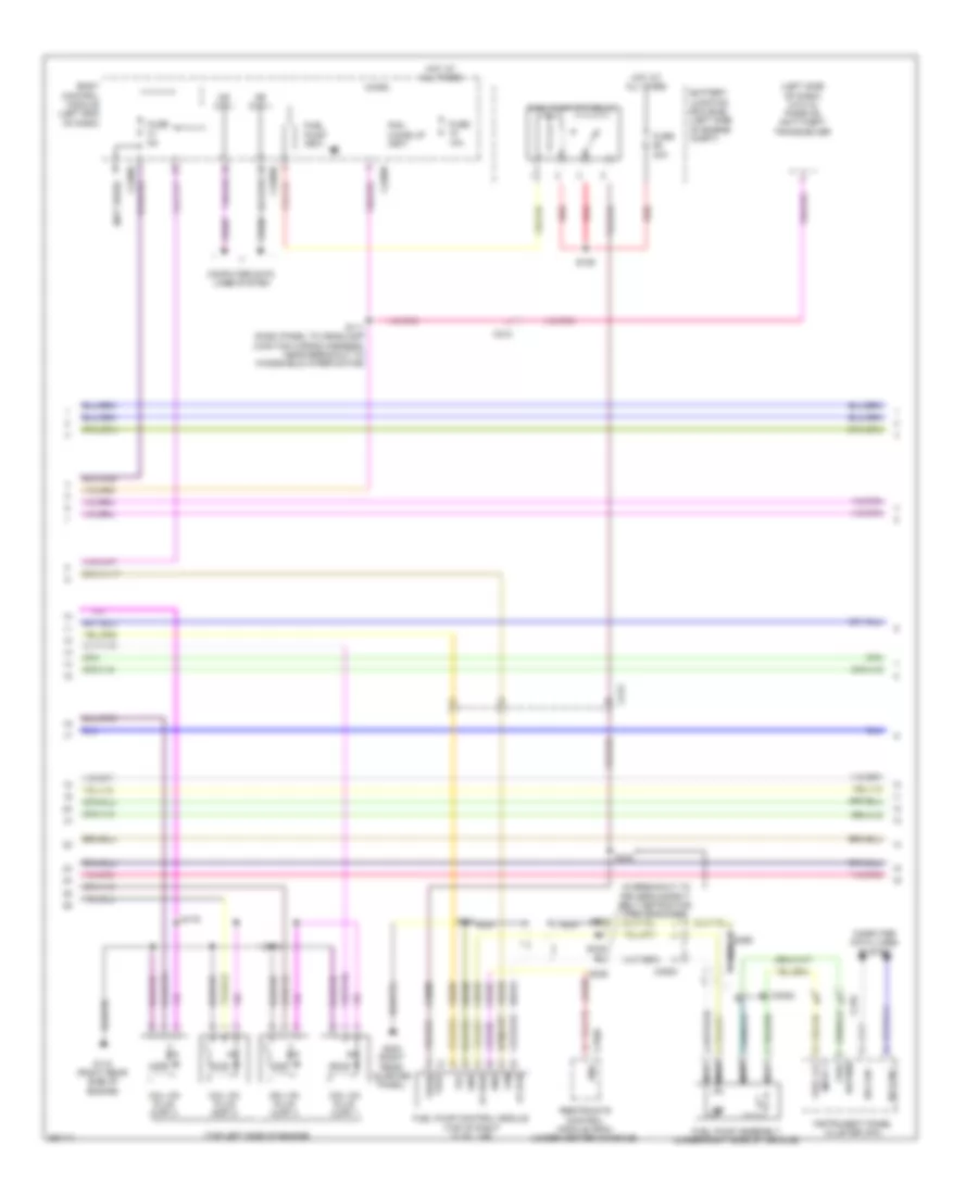
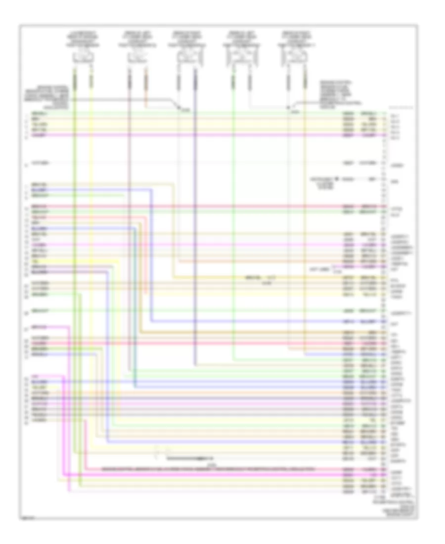
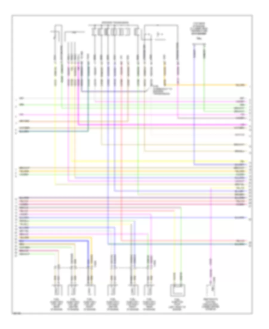
2.0L Turbo, Engine Performance Wiring Diagram (4 of 6) for Ford Explorer 2013
 https://portal-diagnostov.com/license.html
Automotive Electricians Portal FZCO
Automotive Electricians Portal FZCO
https://portal-diagnostov.com/license.html
https://portal-diagnostov.com/license.html
Automotive Electricians Portal FZCO
Automotive Electricians Portal FZCOList of elements for 2.0L Turbo, Engine Performance Wiring Diagram (4 of 6) for Ford Explorer 2013:
- (in breakout to
- (left side of dash) (w/o ia) passive anti-theft transceiver
- (not used)
- (top left side of engine)
- Battery junction box (bjb) (left side of engine compt)
- Body control module (left end of dash)
- C210
- C212
- C213
- C2280b
- C2280f
- C3053
- C310b
- Ce515
- Ce608
- Coil on plug (cop) 1
- Coil on plug (cop) 2
- Coil on plug (cop) 3
- Coil on plug (cop) 4
- Computer data lines system
- Cr167
- Driver's safety belt retractor pretensioner)
- Ens
- Fp pwr
- Fp rtn
- Fpc
- Fpm
- Fuel
- Fuel lvl
- Fuel pump (fet)
- Fuel pump (fp) relay
- Fuel pump assembly (under right side of vehicle)
- Fuel pump control module (top of right "c" pillar)
- Fuel vpwr
- Fuse 10a
- Fuse 30a
- Fuse 5a
- G110 (right rear side of engine)
- G302 (right rear quarter panel)
- Gd348
- Gnd
- Hot at all times
- Hs can +
- Hs can -
- Input 1
- Instrument panel cluster (ipc)
- Micro
- Ms can +
- Ms can -
- Nca
- Pcm wake up (fet)
- Re515
- Red
- Restraints control module (rcm) (under center console)
- Return
- S111 (dash panel to headlamp junction wiring harness, near breakout to windshield wiper motor)
- S129
- S174
- S175
- S329
- S333
- S334
- S335
- S336
- S396
- Vdb06
- Vdb07
- Ve225
- Ve518
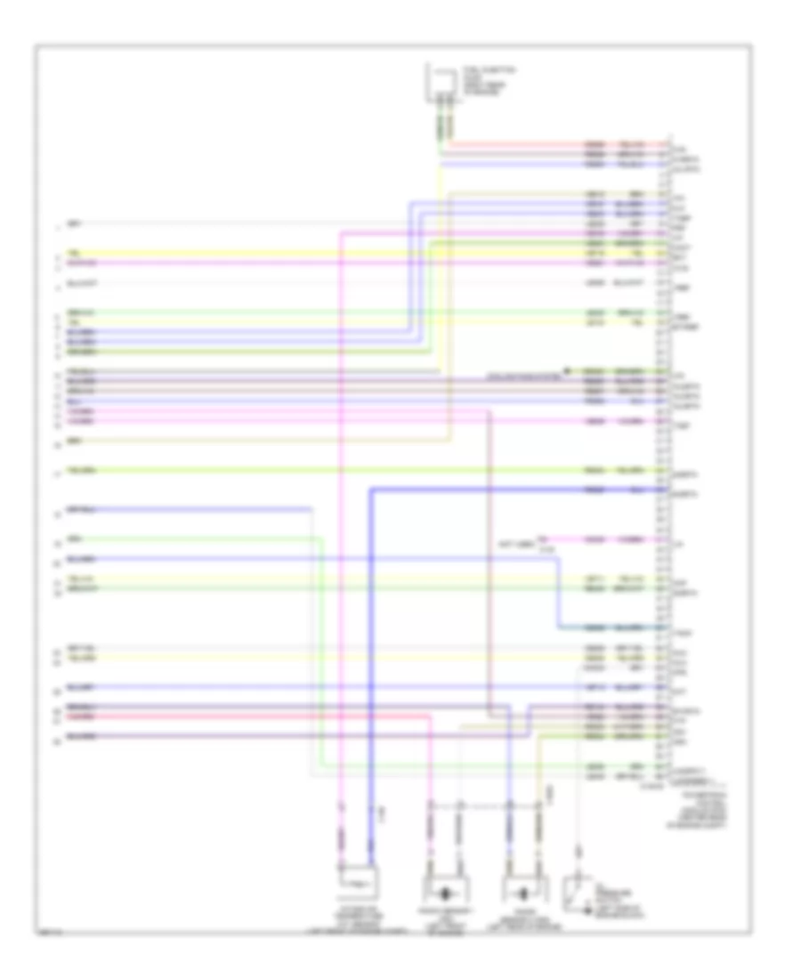
2.0L Turbo, Engine Performance Wiring Diagram (5 of 6) for Ford Explorer 2013
 https://portal-diagnostov.com/license.html
Automotive Electricians Portal FZCO
Automotive Electricians Portal FZCO
https://portal-diagnostov.com/license.html
https://portal-diagnostov.com/license.html
Automotive Electricians Portal FZCO
Automotive Electricians Portal FZCOList of elements for 2.0L Turbo, Engine Performance Wiring Diagram (5 of 6) for Ford Explorer 2013:
- (cop) 2)
- (engine control sensor & fuel charge wiring assembly, near breakout coil on plug
- (engine control sensor & fuel charge wiring assembly, near breakout powertrain control module
- (engine control sensor & fuel charge wiring assembly, near breakout to powertrain control module (pcm))
- (left front of engine) manifold absolute pressure (map) sensor
- (left rear of engine) camshaft position (cmp) sensor 11
- (lower right side of engine) wastegate vacuum sensor
- (near breakout coil on plug 3) s177
- (on fuel rail) fuel rail pressure (frp) sensor
- (pcm)
- (rear of engine) engine coolant temperature (ect) sensor
- (right rear of engine) camshaft position (cmp) sensor 12
- (right side of engine) crankshaft position (ckp) sensor
- (top left side of engine )
- C1033
- Cylinder head temperature (cht) sensor
- Electronic throttle control (etc) (throttle body)
- Fuel injector
- S170
- S171
- S176
2.0L Turbo, Engine Performance Wiring Diagram (6 of 6) for Ford Explorer 2013
 https://portal-diagnostov.com/license.html
Automotive Electricians Portal FZCO
Automotive Electricians Portal FZCO
https://portal-diagnostov.com/license.html
https://portal-diagnostov.com/license.html
Automotive Electricians Portal FZCO
Automotive Electricians Portal FZCOList of elements for 2.0L Turbo, Engine Performance Wiring Diagram (6 of 6) for Ford Explorer 2013:
- (not used) c140
- C1033
- C1381e
- C140
- Cact
- Ce206
- Ce208
- Ce226
- Ce426
- Cec02
- Cht
- Ckp
- Cmc24
- Cooling fans system
- Ect
- Etcref
- Etcrtn
- Flp
- Frp
- Ftp
- Fuel injection pump (right rear of engine)
- Fvr
- Fvrrtn
- Iat
- Inj1rtn
- Inj2
- Inj2rtn
- Inj3rtn
- Inj4
- Inj4rtn
- Intake air temperature (iat) sensor (left front of engine compt)
- Knock sensor 1 (ks1) (left front of engine)
- Knock sensor 2 (ks2) (left rear of engine)
- Ks1-
- Ks2-
- Le134
- Le238
- Le423
- Le448
- Le452
- Le458
- Lfc
- Lin
- Oil pressure switch (left side of engine block)
- Ops
- Powertrain control module (pcm) (center rear of engine compt)
- Re134
- Re205
- Re206
- Re207
- Re208
- Re226
- Re320
- Re323
- Re324
- Re405
- Re454
- Sigrtn
- Tacm-
- Tcbp
- Tcby
- Tp1
- Uo2sgref11
- Uo2spc11
- Vdn08
- Ve711
- Ve712
- Ve716
- Ve727
- Ve740
- Ve803
- Ve804
- Ve818
- Ve821
- Ve836
- Ve922
- Vref
- Wvs
3.5L
3.5L, Engine Performance Wiring Diagram (1 of 6) for Ford Explorer 2013
 https://portal-diagnostov.com/license.html
Automotive Electricians Portal FZCO
Automotive Electricians Portal FZCO
https://portal-diagnostov.com/license.html
https://portal-diagnostov.com/license.html
Automotive Electricians Portal FZCO
Automotive Electricians Portal FZCOList of elements for 3.5L, Engine Performance Wiring Diagram (1 of 6) for Ford Explorer 2013:
- (at generator) generator current sensor
- (dash panel to headlamp junction wiring assembly, near breakout to battery junction box (bjb)) s121
- (dash panel to headlamp junction wiring assembly, near breakout to windshield wiper motor) s143
- (left side of dash) accelerator pedal position sensor
- (under right side of vehicle) evaporative emission canister vent valve
- A/c pressure transducer (right front corner of engine compt)
- Aat
- Accr
- Acpt
- Air conditioning system
- App1
- App2
- Apprtn 1
- Apprtn2
- Appvref 1
- Appvref2
- Awdc
- Awdm
- Battery junction box (left side of engine compt)
- Bcs2 alt
- Bpp
- Bps
- C139
- C175b
- C212
- C213
- C2238
- C3053
- Canv
- Case gnd
- Cbb69
- Cbb90
- Ccb08
- Cdc10
- Cdc12
- Cdc15
- Cdc35
- Ce114
- Ce237
- Ce336
- Ce436
- Ce608
- Cec07
- Cec08
- Ces09
- Cet42
- Cet43
- Ch302
- Computer data lines system
- Cooling fans system
- Digital
- Fpc
- Fpm
- Ftp
- Fuel tank pressure sensor (under right side of vehicle)
- Fuse 10a
- G106 (right side of engine compt bulkhead)
- Gd113
- Gencom
- Genmon
- Hfc
- Hot in start or run
- Hs can +
- Hs can -
- Iat
- Injpwrm
- Isp r
- Kapwr
- Le136
- Le137
- Le230
- Le424
- Lfc
- Maf
- Mass air flow/ intake air temperature sensor (left front of engine compt)
- Pcm wake
- Pcmrc
- Police
- Powertrain control module (center rear of engine compt)
- Pwr gnd
- Re136
- Re137
- Re320
- Re407
- S114
- Sbb86
- Sig rtn
- Sigrtn
- Smc
- Smcs
- Sst-d
- Sst-u
- Start
- Starting/charging system
- Tapped to harness near c2238
- Transmissions system
- Vcf34
- Vcf35
- Vdb04
- Vdb05
- Vdc61
- Ve225
- Ve518
- Ve701
- Ve702
- Ve740
- Ve807
- Ve922
- Vh407
- Vh433
- Vmc05
- Vpwr
- Vref
- Vref 5v
- Vso
3.5L, Engine Performance Wiring Diagram (2 of 6) for Ford Explorer 2013
 https://portal-diagnostov.com/license.html
Automotive Electricians Portal FZCO
Automotive Electricians Portal FZCO
https://portal-diagnostov.com/license.html
https://portal-diagnostov.com/license.html
Automotive Electricians Portal FZCO
Automotive Electricians Portal FZCOList of elements for 3.5L, Engine Performance Wiring Diagram (2 of 6) for Ford Explorer 2013:
- (behind left side of grille) ambient air temperature sensor
- (body main wiring assembly, in breakout to driver's safety belt retractor pretensioner)
- (main wiring assembly, near breakout to c2123)
- (main wiring assembly, near breakout to defrost/panel/floor mode door actuator)
- (main wiring harness, near near breakout to hs-can
- (on throttle body) electronic throttle control
- (under center console) brake shift interlock
- (w/console: under center console) (w/o console: left side of dash) center stack switch assembly
- Body control module (left end of dash)
- C140
- C212
- C213
- C2280b
- C237
- C263
- C3053
- C310b
- Ce515
- Ce608
- Computer data lines system
- Cr167
- Ens
- Fpc
- Fpm
- Fppwr
- Fprtn
- Fuel pump assembly (under right side of vehicle)
- Fuel pump control module (top of right "c" pillar)
- Fuse 5a
- Fuse 7.5a
- G302 (right rear quarter panel)
- Gd348
- Gnd
- Hot in start or run
- Hs can +
- Hs can -
- Instrument cluster system
- Instrument panel cluster (ipc)
- Joint connector 6)
- Lower gear selector switch
- Nca
- Re515
- Restraints control module (under center console)
- S202
- S210
- S217
- S244 (w/ paddle shift)
- S245 (w/ paddle shift)
- S329
- S333 (body main wiring assembly, in breakout to driver's safety belt retractor pretensioner)
- S334
- S335
- S336
- S396
- Sst-d
- Sst-u
- Tow haul
- Transmissions system
- Ve225
- Ve518
- Vpwr fuel
- W/ column shifter
- W/ floor shifter
3.5L, Engine Performance Wiring Diagram (3 of 6) for Ford Explorer 2013
 https://portal-diagnostov.com/license.html
Automotive Electricians Portal FZCO
Automotive Electricians Portal FZCO
https://portal-diagnostov.com/license.html
https://portal-diagnostov.com/license.html
Automotive Electricians Portal FZCO
Automotive Electricians Portal FZCOList of elements for 3.5L, Engine Performance Wiring Diagram (3 of 6) for Ford Explorer 2013:
- (center rear of engine compt) (w/ power takeoff unit) power takeoff sensor
- (dash panel to headlamp junction wiring assembly, near breakout to battery junction box (bjb)) s120
- Battery junction box (left side of engine compt)
- C139
- C140
- C175t
- Ce233
- Ce234
- Cet05
- Cet06
- Cet07
- Cet08
- Cet09
- Cet10
- Cet19
- Cet25
- Cet34
- Fuel pump (fp) relay
- Fuse 10a
- Fuse 20a
- Fuse 30a
- Fuse 7.5a
- Heated oxygen sensor 12 (right exhaust pipe, after catalytic converter)
- Ho2s12
- Ho2s22
- Hot at all times
- Htr12
- Htr22
- Le111
- Lpc
- Nca
- Oss
- Pcm power relay
- Re406
- Red
- Ret04
- Ret24
- Ret33
- S115
- S117
- S129
- S134
- Sigrtn
- Ssa
- Ssb
- Ssc
- Ssd
- Sse
- Tcc
- Tft
- Tows
- Tr 1
- Tr 2
- Tr 3
- Tr 4
- Tspc powertrain control module (center rear of engine compt)
- Tss
- Tss/oss/tr gnd
- Ve731
- Ve733
- Vet27
- Vet29
- Vet30
- Vet31
- Vet32
- Vref
3.5L, Engine Performance Wiring Diagram (4 of 6) for Ford Explorer 2013
 https://portal-diagnostov.com/license.html
Automotive Electricians Portal FZCO
Automotive Electricians Portal FZCO
https://portal-diagnostov.com/license.html
https://portal-diagnostov.com/license.html
Automotive Electricians Portal FZCO
Automotive Electricians Portal FZCOList of elements for 3.5L, Engine Performance Wiring Diagram (4 of 6) for Ford Explorer 2013:
- (dash panel to headlamp junction wiring assembly, near breakout to windshield wiper motor)
- (dash panel to headlamp junction wiring assembly, near breakout to windshield wiper motor) s111
- (front wheel drive (fwd) engine wiring assembly, in breakout to 6f50/6f55 transmission) s159
- (left side of dash) (w/o intelligent access)
- (not used)
- (top center of engine) cylinder head temperature sensor
- (under glove box) (w/ intelligent access) remote function actuator module
- 6f50/6f55 transmission
- Body control module (left end of dash)
- Bpp
- Brake pedal position switch (above brake pedal)
- C192
- C212
- C2153c
- C2280b
- C2280f
- C299
- Ccb08
- Cet05
- Cet06
- Cet07
- Cet08
- Cet09
- Cet10
- Cet19
- Cet25
- Computer data lines system
- Except police
- Fuel pump (fet)
- Fuse 10a
- Fuse 5a
- G106 (right side of engine compt bulkhead)
- Heated oxygen sensor 22 (left exhaust pipe, after catalytic converter)
- Hot at all times
- Le111
- Lpc
- Micro
- Ms can +
- Ms can -
- Nca
- Oss
- Passive anti-theft transceiver
- Pcm wake up (fet)
- Police
- Re406
- Ret04
- Ret24
- Ret33
- S112
- S114
- S156 (engine control sensor & fuel charge wiring assembly, near breakout to fuel injector 3)
- Ssa
- Ssb
- Ssc
- Ssd
- Sse
- Tcc
- Tft
- Tft sig rtn
- Tr 1
- Tr 2
- Tr 3
- Tr 4
- Tr gnd
- Trailer brake control module connector
- Trs
- Tspc
- Tss
- Tss/oss gnd
- Tss/oss vpwr
- Universal heated oxygen sensor 11 (right exhaust pipe, before catalytic converter)
- Universal heated oxygen sensor 21 (left exhaust pipe, before catalytic converter)
- Vdb06
- Vdb07
- Vet27
- Vet29
- Vet30
- Vet31
- Vet32
3.5L, Engine Performance Wiring Diagram (5 of 6) for Ford Explorer 2013
 https://portal-diagnostov.com/license.html
Automotive Electricians Portal FZCO
Automotive Electricians Portal FZCO
https://portal-diagnostov.com/license.html
https://portal-diagnostov.com/license.html
Automotive Electricians Portal FZCO
Automotive Electricians Portal FZCOList of elements for 3.5L, Engine Performance Wiring Diagram (5 of 6) for Ford Explorer 2013:
- (left front of engine) vct solenoid 21
- (left front of engine) vct solenoid 22
- (right front of engine) vct solenoid 11
- (right front of engine) vct solenoid 12
- (right rear of engine) evaporative emission purge valve
- (top rear of engine) knock sensor
- C140
- Coil on plug (cop) 1 (top right front of engine)
- Coil on plug (cop) 2 (top right center of engine)
- Coil on plug (cop) 3 (top right rear of engine)
- Coil on plug (cop) 4 (top left front of engine)
- Coil on plug (cop) 5 (top left center of engine)
- Coil on plug (cop) 6 (top left rear of engine)
- Fuel injector 1 (top right front of engine)
- Fuel injector 2 (top right center of engine)
- Fuel injector 3 (top right rear of engine)
- Fuel injector 4 (top left front of engine)
- Fuel injector 5 (top left center of engine)
- Fuel injector 6 (top left rear of engine)
- S154
- S155
- S157
- S158
- Tan
3.5L, Engine Performance Wiring Diagram (6 of 6) for Ford Explorer 2013
 https://portal-diagnostov.com/license.html
Automotive Electricians Portal FZCO
Automotive Electricians Portal FZCO
https://portal-diagnostov.com/license.html
https://portal-diagnostov.com/license.html
Automotive Electricians Portal FZCO
Automotive Electricians Portal FZCOList of elements for 3.5L, Engine Performance Wiring Diagram (6 of 6) for Ford Explorer 2013:
- (engine control sensor & fuel charge wiring assembly, near breakout powertrain control module (pcm))
- (engine control sensor & fuel charge wiring assembly, near breakout to powertrain control module)
- (lower right rear of engine) crankshaft position sensor
- (not used) c140
- (rear of left cylinder head) camshaft position sensor 21
- (rear of left cylinder head) camshaft position sensor 22
- (rear of right cylinder head) camshaft position sensor 11
- (rear of right cylinder head) camshaft position sensor 12
- Aat
- C140
- C175e
- Ce113
- Ce205
- Ce206
- Ce207
- Ce208
- Ce209
- Ce210
- Ce235
- Ce236
- Ce303
- Ce304
- Ce305
- Ce306
- Ce307
- Ce308
- Ce412
- Ce421
- Ce422
- Ce426
- Ce442
- Ce443
- Cht
- Ckp+
- Ckp-
- Cmc24
- Cmp11
- Cmp12
- Cmp21
- Cmp22
- Cop1a
- Cop2c
- Cop3e
- Cop4b
- Cop5d
- Cop6f
- De135
- Etcref
- Etcrtn
- Evapcp
- Inj 1
- Inj 2
- Inj 3
- Inj 4
- Inj 5
- Inj 6
- Instrument cluster system
- Ks1+
- Ks1-
- Ks2+
- Ks2-
- Le134
- Le448
- Le449
- Le450
- Le451
- Le452
- Le453
- Nca
- Ops
- Powertrain control module (center rear of engine compt)
- Pto
- Re134
- Re135
- Re323
- Re324
- Re405
- Re429
- S150
- S151
- S160
- Shdrtn
- Sigrtn
- Tacm+
- Tacm-
- Tp1
- Tp2
- Uo2s11
- Uo2s21
- Uo2sgref11
- Uo2sgref21
- Uo2shtr11
- Uo2shtr21
- Uo2spc11
- Uo2spc21
- Uo2spct11
- Uo2spct21
- Vct11
- Vct12
- Vct21
- Vct22
- Ve706
- Ve707
- Ve711
- Ve712
- Ve740
- Ve801
- Ve802
- Ve818
- Ve819
- Ve826
- Ve827
- Vet27
- Vrsrtn
- Vrsrtn2
3.5L TWIN TURBO
3.5L Twin Turbo, Engine Performance Wiring Diagram (1 of 7) for Ford Explorer 2013
 https://portal-diagnostov.com/license.html
Automotive Electricians Portal FZCO
Automotive Electricians Portal FZCO
https://portal-diagnostov.com/license.html
https://portal-diagnostov.com/license.html
Automotive Electricians Portal FZCO
Automotive Electricians Portal FZCOList of elements for 3.5L Twin Turbo, Engine Performance Wiring Diagram (1 of 7) for Ford Explorer 2013:
- (center rear of engine compt) (w/ power takeoff unit) power takeoff sensor
- (dash panel to headlamp junction wiring assembly, near breakout to
- (dash panel to headlamp junction wiring assembly, near breakout to windshield wiper motor)
- (fuel tank jumper wiring assembly, near breakout to c3123) s398
- (fuel tank jumper wiring assembly, near breakout to c3270)
- (under right side of vehicle) fuel pressure sensor
- (under right side of vehicle) fuel tank pressure (ftp) sensor
- A/c pressure transducer (right front corner of engine compt)
- Aat
- Accelerator pedal position (app) sensor (left side of dash)
- Accr
- Acpt
- Air conditioning system
- App1
- App2
- Apprtn1
- Apprtn2
- Appvref1
- Appvref2
- Awdc
- Awdm
- Battery junction box (bjb))
- Body control module (bcm) (left end of dash)
- Bpp
- Bps
- C139
- C140
- C1551b
- C212
- C213
- C2280f
- C3053
- Cact
- Canv
- Cbb90
- Ccb08
- Cdc10
- Cdc12
- Cdc15
- Cdc35
- Ce113
- Ce114
- Ce233
- Ce234
- Ce237
- Ce336
- Ce436
- Cec07
- Cec08
- Ces09
- Ch302
- Computer data lines system
- Cooling fans system
- Evapcp
- Evdc
- Fpc
- Fpm
- Fuse 10a
- Gencom
- Generator current sensor (at generator)
- Genmon
- Heated oxygen sensor (ho2s) 12 (right exhaust pipe, after catalytic converter)
- Heated oxygen sensor (ho2s) 22 (left exhaust pipe, after catalytic converter)
- Hfc
- Ho2s12
- Ho2s22
- Hot at all times
- Hs can +
- Hs can -
- Hs can+
- Hs can-
- Htr12
- Htr22
- Isp-r
- Le136
- Le137
- Le230
- Le424
- Lfc
- Micro
- Nca
- Passive anti-theft transceiver (w/o intelligent access) (left side of dash)
- Pcm wake
- Pcm wake up (fet)
- Pcmrc
- Powertrain control module (pcm) (center rear of engine compt)
- Re136
- Re137
- Re230
- Re242
- Re249
- Re407
- Res09
- S111
- S121
- S143
- S397
- Sigrtn
- Smc
- Smcs
- Start
- Starting/ charging system
- Starting/charging system
- Vcf34
- Vcf35
- Vdb04
- Vdb05
- Ve225
- Ve462
- Ve518
- Ve701
- Ve702
- Ve731
- Ve733
- Ve751
- Vh407
- Vh433
- Vref
3.5L Twin Turbo, Engine Performance Wiring Diagram (2 of 7) for Ford Explorer 2013
 https://portal-diagnostov.com/license.html
Automotive Electricians Portal FZCO
Automotive Electricians Portal FZCO
https://portal-diagnostov.com/license.html
https://portal-diagnostov.com/license.html
Automotive Electricians Portal FZCO
Automotive Electricians Portal FZCOList of elements for 3.5L Twin Turbo, Engine Performance Wiring Diagram (2 of 7) for Ford Explorer 2013:
- (dash panel to headlamp junction wiring assembly, near breakout to windshield wiper motor)
- (front right of engine compt) externally controlled variable displacement compressor (evdc)
- (under right side of vehicle) evaporative emission (evap) canister vent valve
- 7.5a
- All wheel drive (awd) relay module (left "d" pillar)
- Ambient air temperature (aat) sensor (behind left side of grille)
- Awdc
- Awdm
- Battery junction box (bjb) (left side of engine compt)
- Brake pedal position (bpp) switch (above brake pedal)
- Breakout to clockspring)
- C139
- C140
- C213
- C218a
- C218b
- C218c
- C2414a
- C3053
- Clockspring (top of steering column)
- Fuse
- Fuse 10a
- Fuse 20a
- G106 (right side of engine compt bulkhead)
- G201 (under right front of center console)
- Hot at all times
- Hot in run or start
- Interior lights system
- Left paddle shifter
- Nca
- Pcm power relay
- Pnk
- Right paddle shifter
- S112
- S113
- S117
- S134
- S197
- S294 (steering wheel jumper wiring assembly, near nca
- S296
- Steering column control module (sccm) (top of steering column) c2414d
- Turbocharger boost pressure/charge air cooler temperature (tcbp/cact) sensor (in air intake duct)
- Vcf34
- Vcf35
3.5L Twin Turbo, Engine Performance Wiring Diagram (3 of 7) for Ford Explorer 2013
 https://portal-diagnostov.com/license.html
Automotive Electricians Portal FZCO
Automotive Electricians Portal FZCO
https://portal-diagnostov.com/license.html
https://portal-diagnostov.com/license.html
Automotive Electricians Portal FZCO
Automotive Electricians Portal FZCOList of elements for 3.5L Twin Turbo, Engine Performance Wiring Diagram (3 of 7) for Ford Explorer 2013:
- (left front of engine compt) intake air temperature (iat) sensor
- (main wiring assembly, near breakout to c2123)
- (main wiring assembly, near breakout to defrost/panel/floor mode door actuator)
- (not used) ce608
- (under glove box) (w/ intelligent access) remote function (rfa) actuator module
- (w/ console: under center console) (w/o console: left side of dash) brake shift interlock
- Battery junction box (bjb) (left side of engine compt)
- Bcs2 alt
- Body control module (bcm) (left end of dash)
- Bpp
- C1551b
- C1551e
- C212
- C213
- C2153c
- C2280b
- C2280f
- C237
- Cbb69
- Ccb08
- Ce205
- Ce206
- Ce207
- Ce208
- Ce209
- Ce210
- Ce226
- Ce305
- Ce308
- Ce412
- Ce426
- Cet07
- Cet25
- Cet34
- Cet42
- Cet43
- Cop3e
- Cop6f
- Flp
- Ftp
- Fuel pump (fet)
- Fuel pump relay
- Fuse 30a
- Fvr
- Fvrrtn
- G106 (right side of engine compt bulkhead)
- Gd113
- Hot at all times
- Iat
- Inj1
- Inj1rtn
- Inj2
- Inj2rtn
- Inj3
- Inj3rtn
- Inj4
- Inj4rtn
- Inj5
- Inj5rtn
- Inj6
- Inj6rtn
- Micro
- Nca
- Powertrain control module (pcm) (center rear of engine compt)
- Pto
- Pwrgnd
- Re205
- Re206
- Re207
- Re208
- Re209
- Re210
- Re226
- Red
- S115
- S116
- S120 (dash panel to headlamp junction wiring assembly, near breakout to battery junction box (bjb))
- S129
- S244
- S245
- S333 (body main wiring assembly, in breakout to driver's safety belt retractor pretensioner)
- Sbb86
- Ssc
- Sst-d
- Starting/ charging system
- Stt-u
- Tacm+
- Tacm-
- Tcbp
- Tows
- Transmissions system
- Tspc
- Vbatt
- Vdc61
- Ve740
- Ve804
- Ve830
- Ve922
- Vet27
- Vpwr
- W/ floor shifter
- W/ paddle shifter
3.5L Twin Turbo, Engine Performance Wiring Diagram (4 of 7) for Ford Explorer 2013
 https://portal-diagnostov.com/license.html
Automotive Electricians Portal FZCO
Automotive Electricians Portal FZCO
https://portal-diagnostov.com/license.html
https://portal-diagnostov.com/license.html
Automotive Electricians Portal FZCO
Automotive Electricians Portal FZCOList of elements for 3.5L Twin Turbo, Engine Performance Wiring Diagram (4 of 7) for Ford Explorer 2013:
- (top rear of engine) cylinder head temperature (cht) sensor
- 6f50/6f55 transmission
- C1045
- C1046
- C310b
- Cet05
- Cet06
- Cet07
- Cet08
- Cet09
- Cet10
- Cet19
- Cet25
- Cr167
- Ens
- Fuel injection pump (left front of engine)
- Fuel injector 1 (top right front of engine)
- Fuel injector 2 (top right center of engine)
- Fuel injector 3 (top right rear of engine)
- Fuel injector 4 (top left front of engine)
- Fuel injector 5 (top left center of engine)
- Fuel injector 6 (top left rear of engine)
- Le111
- Lpc
- Oss
- Re405
- Restraints control module (rcm) (under center console)
- Ret04
- Ret24
- Ret33
- S159 (in breakout to 6f50/6f55 transmission)
- Ssa
- Ssb
- Ssc
- Ssd
- Sse
- Tcc
- Tft
- Tr gnd
- Tr-1
- Tr-2
- Tr-3
- Tr-4
- Trs
- Tspc
- Tss
- Tss/oss gnd
- Tss/oss vpwr
- Vet27
- Vet29
- Vet30
- Vet31
- Vet32
3.5L Twin Turbo, Engine Performance Wiring Diagram (5 of 7) for Ford Explorer 2013
 https://portal-diagnostov.com/license.html
Automotive Electricians Portal FZCO
Automotive Electricians Portal FZCO
https://portal-diagnostov.com/license.html
https://portal-diagnostov.com/license.html
Automotive Electricians Portal FZCO
Automotive Electricians Portal FZCOList of elements for 3.5L Twin Turbo, Engine Performance Wiring Diagram (5 of 7) for Ford Explorer 2013:
- (body main wiring assembly, in breakout to
- (engine control sensor & fuel charge wiring assembly, near breakout to camshaft position 11 (cmp11) sensor)
- (engine control sensor & fuel charge wiring assembly, near breakout to evaporative emission (evap) purge valve) s1004
- (lower left rear of engine) crankshaft position (ckp) sensor
- (near breakout to camshaft
- (on fuel rail) fuel rail pressure (frp) sensor
- (rear of left cylinder head) camshaft position (cmp21) sensor 21
- (rear of right cylinder head) camshaft position (cmp11) sensor 11
- (top rear of engine) manifold absolute pressure/intake air temperature 2 (map/iat2) sensor
- C1046
- C210
- C3053
- Ce515
- Ce608
- Computer data lines system
- Cr167
- Driver's safety belt retractor pretensioner)
- Ens
- Fpc
- Fpm
- Fppwr
- Fprtn
- Fuel lvl
- Fuel lvl2
- Fuel pump (fp) assembly (under right side of vehicle)
- Fuel pump control module (top of right "c" pillar)
- Fuel rtn
- G302 (right rear quarter panel)
- Gd348
- Gnd
- Hs can +
- Hs can -
- Input 1
- Instrument panel cluster (ipc)
- Nca
- Position 11 (cmp11) sensor)
- Re515
- S1006
- S1007
- S1008
- S329
- S334
- S396
- Ve225
- Ve518
- Vpwr
3.5L Twin Turbo, Engine Performance Wiring Diagram (6 of 7) for Ford Explorer 2013
 https://portal-diagnostov.com/license.html
Automotive Electricians Portal FZCO
Automotive Electricians Portal FZCO
https://portal-diagnostov.com/license.html
https://portal-diagnostov.com/license.html
Automotive Electricians Portal FZCO
Automotive Electricians Portal FZCOList of elements for 3.5L Twin Turbo, Engine Performance Wiring Diagram (6 of 7) for Ford Explorer 2013:
- (top of engine) turbocharger bypass valve 2 (tcby2)
- (top rear of engine) turbo- charger (tc) wastegate regulating valve solenoid
- (top right rear of engine) turbocharger bypass valve (tcby)
- C1609a
- C1609b
- Coil on plug (cop) 1 (top right front of engine)
- Coil on plug (cop) 2 (top right center of engine)
- Coil on plug (cop) 3 (top right rear of engine)
- Coil on plug (cop) 4 (top left front of engine)
- Coil on plug (cop) 5 (top left center of engine)
- Coil on plug (cop) 6 (top left rear of engine)
- Electronic throttle control (etc) (throttle body)
- Fuel level sensor (in fuel tank)
- G111 (right rear of engine)
- G112 (left rear of engine)
- Pnk
- S1002
- S1003
- S1005
- S1009
- S1010
3.5L Twin Turbo, Engine Performance Wiring Diagram (7 of 7) for Ford Explorer 2013
 https://portal-diagnostov.com/license.html
Automotive Electricians Portal FZCO
Automotive Electricians Portal FZCO
https://portal-diagnostov.com/license.html
https://portal-diagnostov.com/license.html
Automotive Electricians Portal FZCO
Automotive Electricians Portal FZCOList of elements for 3.5L Twin Turbo, Engine Performance Wiring Diagram (7 of 7) for Ford Explorer 2013:
- (left front of engine) variable camshaft timing (vct21) solenoid 21
- (right front of engine) variable camshaft timing (vct11) solenoid 11
- (right rear of engine) evaporative emission (evap) purge valve
- C140
- C1551e
- Ce235
- Ce236
- Ce303
- Ce304
- Ce306
- Ce307
- Ce421
- Ce422
- Ce435
- Cet05
- Cet06
- Cet08
- Cet09
- Cet10
- Cet19
- Cht
- Ckp
- Cmc24
- Cmp11
- Cmp21
- Cop 1a
- Cop2c
- Cop4b
- Cop5d
- Etcref
- Etcrtn
- Frp
- Iat2
- Knock sensor (ks) (top rear of engine)
- Ks1 +
- Ks1 -
- Ks2 +
- Ks2 -
- Le111
- Le134
- Le423
- Le448
- Le449
- Le450
- Le451
- Le452
- Le453
- Lpc
- Map
- Oil pressure switch (left side of engine block)
- Ops
- Oss
- Powertrain control module (pcm) (center rear of engine compt)
- Re134
- Re323
- Re324
- Re405
- Re406
- Red
- Ret04
- Ret24
- Ret33
- S1001
- Sigrtn
- Ssa
- Ssb
- Ssd
- Sse
- Tan
- Tcby
- Tcby2
- Tcc
- Tcwrvs
- Tft
- Tp 1
- Tp2
- Tr gnd
- Tr-1
- Tr-2
- Tr-3
- Tr-4
- Tss
- Universal heated oxygen sensor (ho2s) 11 (right exhaust pipe, before catalytic converter)
- Universal heated oxygen sensor (ho2s) 21 (left exhaust pipe, before catalytic converter)
- Uo2s11
- Uo2s21
- Uo2sgref11
- Uo2sgref21
- Uo2shtr11
- Uo2shtr21
- Uo2spc11
- Uo2spc21
- Uo2spct21
- Uo2ssptc11
- Vct11
- Vct21
- Ve706
- Ve707
- Ve711
- Ve712
- Ve727
- Ve740
- Ve801
- Ve802
- Ve804
- Ve818
- Ve819
- Ve824
- Ve826
- Ve827
- Vet27
- Vet29
- Vet30
- Vet31
- Vet32
- Vref

 Čeština
 Dansk
Dansk Deutsch
 Ελληνικά
 English
 English
 Español
 Suomi
Suomi Français
 Français
 עברית
עברית Hrvatski
 Magyar
 Italiano
 日本語
日本語 한국어
한국어 Nederlands
 Polski
 Português
 Português
 Română
 Русский
 Slovenčina
 Slovenščina
 Svenska
 Türkçe
