ENGINE PERFORMANCE
4.0L
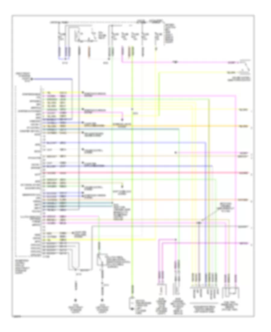
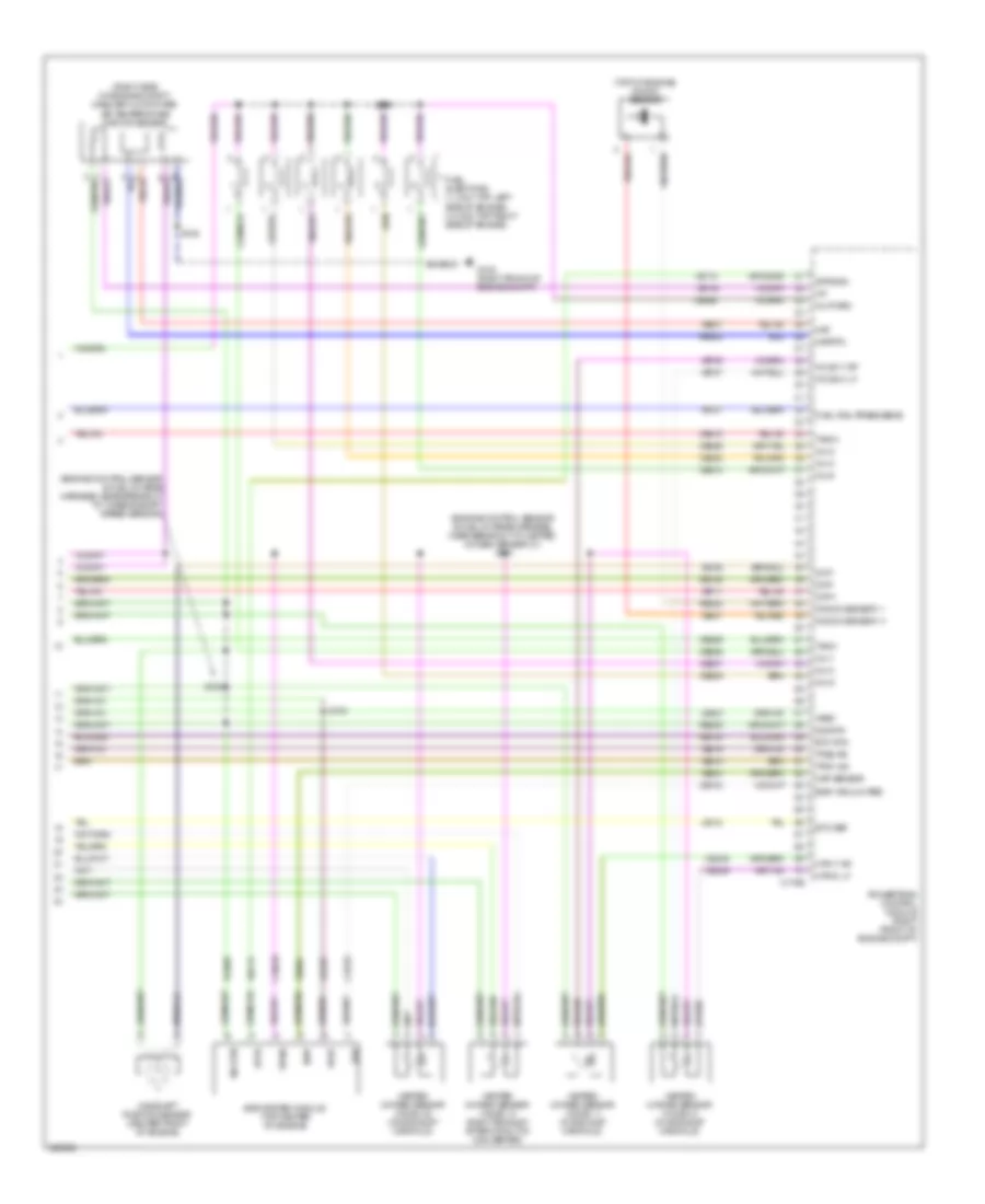
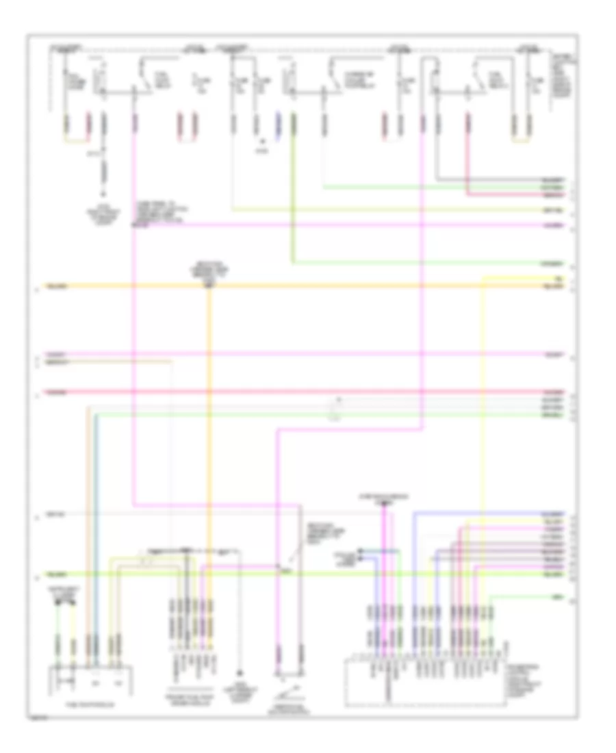
4.0L, Engine Performance Wiring Diagram (1 of 5) for Ford Mustang Shelby GT500 2010
 https://portal-diagnostov.com/license.html
Automotive Electricians Portal FZCO
Automotive Electricians Portal FZCO
https://portal-diagnostov.com/license.html
https://portal-diagnostov.com/license.html
Automotive Electricians Portal FZCO
Automotive Electricians Portal FZCO
List of elements for 4.0L, Engine Performance Wiring Diagram (1 of 5) for Ford Mustang Shelby GT500 2010:
- (body main harness, near breakout to c192)
- (right front of engine compt) g103
- Accelerator pedal position sensor (left side of dash)
- Accr
- Acpt
- Air conditioning/ heater system
- App
- App2
- App3
- Apprtn
- Apprtn2
- Appvref
- Appvref2
- Battery junction box (bjb) (right side of engine compt)
- Bpp
- Bps
- C175b
- Canister vent sol
- Case gnd
- Cbb45
- Cbb47
- Ccb08
- Cdb08
- Cdc10
- Cdc12
- Ce114
- Ce302
- Ce509
- Ce903
- Ce904
- Cet34
- Cet40
- Ch302
- Cls09
- Clutch deact sw man trns ftpref
- Clutch pedal cruise control deactivator switch (clutch pedal support)
- Computer data lines system
- Cpp
- Cruise control deactivation switch
- Cruise control system
- Evap canister purge valve (left side of engine compt)
- Evap canister vent control solenoid (left rear of vehicle)
- Exterior lights system
- Feps
- Fp control
- Fp monitor
- Ftp
- Fuel tank pressure (ftp) sensor (on fuel tank)
- Fuse 10a
- Fuse 15a
- Fuse 30a
- Fuse 5a
- G102 (right front of engine compt)
- G104 (left front of engine compt)
- Gd119
- Generator com
- Ground
- Hot at all times
- Hot in start or run
- Hs can +
- Hs can -
- Ignition transformer capacitor (left cylinder head)
- Isp-r
- Kapwr
- Le136
- Le137
- Le230
- Nca
- Od cancel sw sig
- Pcm power relay
- Pcm rc
- Powertrain control module (right front of engine compt)
- Pspsw
- Re136
- Re137
- Res08
- S104
- S113
- S115
- S116
- S120
- S123 (body main harness, near breakout to powertrain control module)
- S124
- S134
- Sbb23
- Sccs
- Sccs return
- Shift interlock system
- Starter enable
- Starter motor req
- Starting/charging system
- Vbatt
- Vdb04
- Vdb05
- Ve225
- Ve518
- Ve701
- Ve702
- Ve703
- Ve922
- Ves10
- Vh433
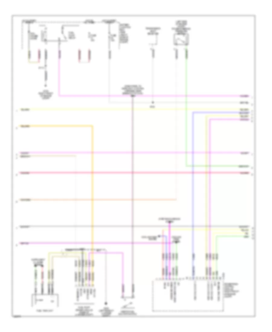
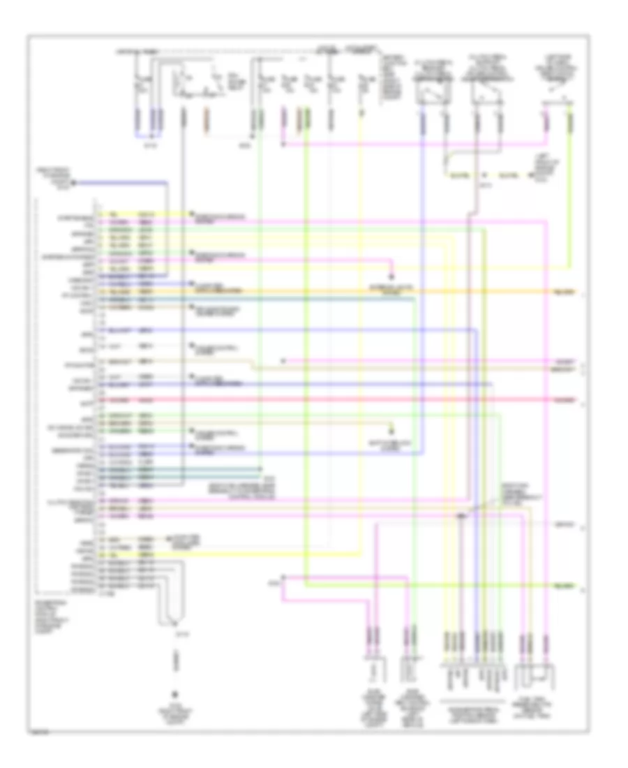
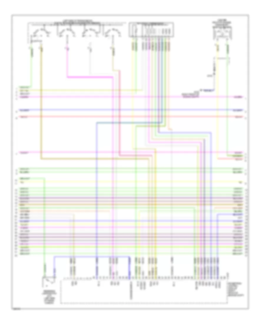
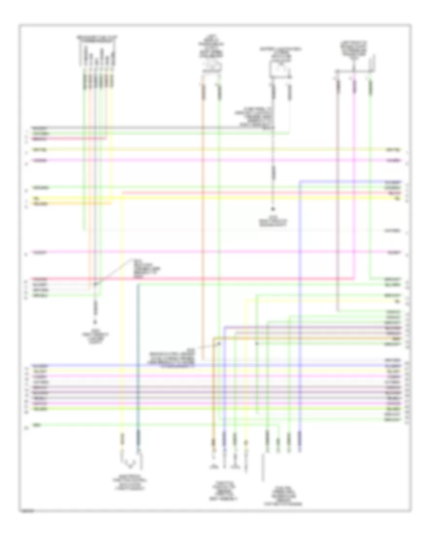
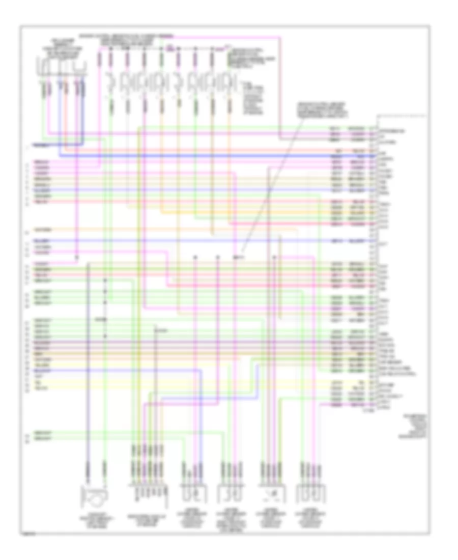
4.0L, Engine Performance Wiring Diagram (2 of 5) for Ford Mustang Shelby GT500 2010
 https://portal-diagnostov.com/license.html
Automotive Electricians Portal FZCO
Automotive Electricians Portal FZCO
https://portal-diagnostov.com/license.html
https://portal-diagnostov.com/license.html
Automotive Electricians Portal FZCO
Automotive Electricians Portal FZCOList of elements for 4.0L, Engine Performance Wiring Diagram (2 of 5) for Ford Mustang Shelby GT500 2010:
- (dash panel to headlight junction harness, near breakout to g100) s135
- (left side of engine compt) power steering pressure switch
- Battery junction box (bjb) (right side of engine compt)
- C175e
- Cdc15
- Ce238
- Ce303
- Ce305
- Ce309
- Ce420
- Ce515
- Ce911
- Cec01
- Cec02
- Cooling fans system
- Ect
- Evap canis pur val
- Fp ctrl
- Fp monitor
- Fp power
- Fp rtn
- Fuel pump driver module (rear of luggage compt)
- Fuel pump relay
- Fuel rail temp sn
- Fuel tank unit
- Fuse 15a
- G100 (right front of engine compt)
- G400 (left rear of luggage compt)
- Gd109
- Generator mon
- Gnd
- Hfc
- Hot at all times
- Hot in start or run
- Ign coil 1 / cop 1
- Ign coil 2 / cop 2
- Ign coil 3 / cop 3
- Inertia fuel shutoff switch
- Instrument cluster system
- Lfc
- Nca
- Pcm power diode
- Pcvhc
- Powertrain control module (right front of engine compt)
- Re515
- S112
- S122
- S407
- Starting/charging
- System
- Transmission shift selector
- Ve225
- Ve518
- Ve716
- Ve728
- Vpwr
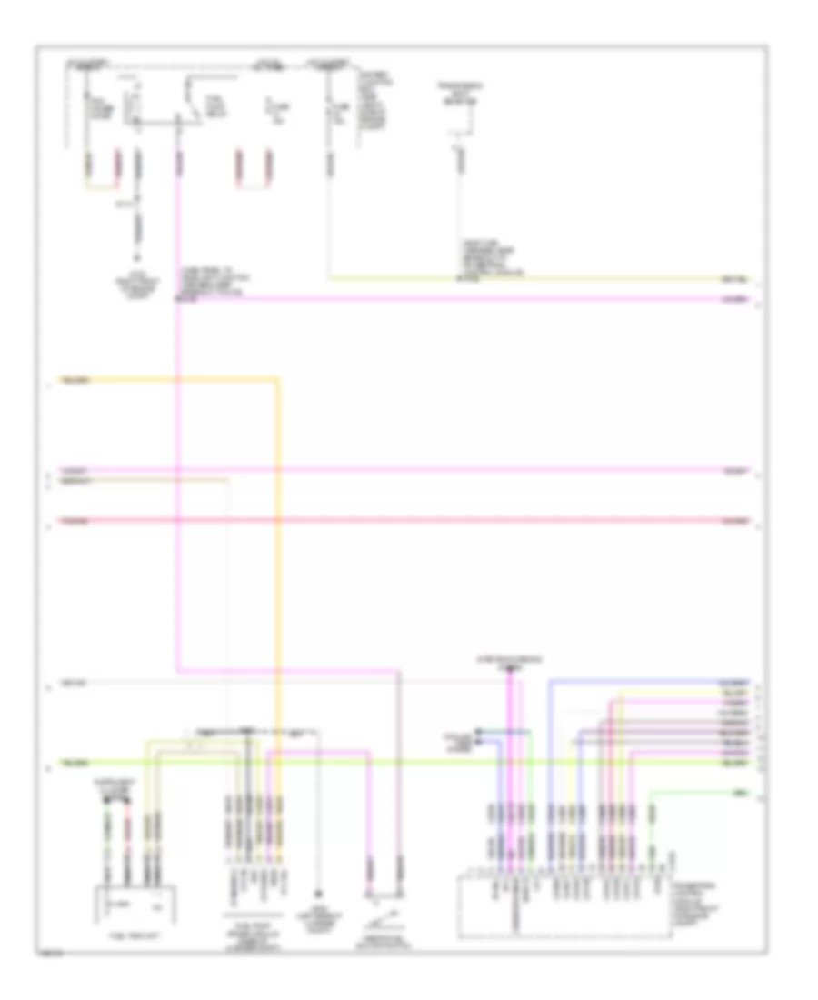
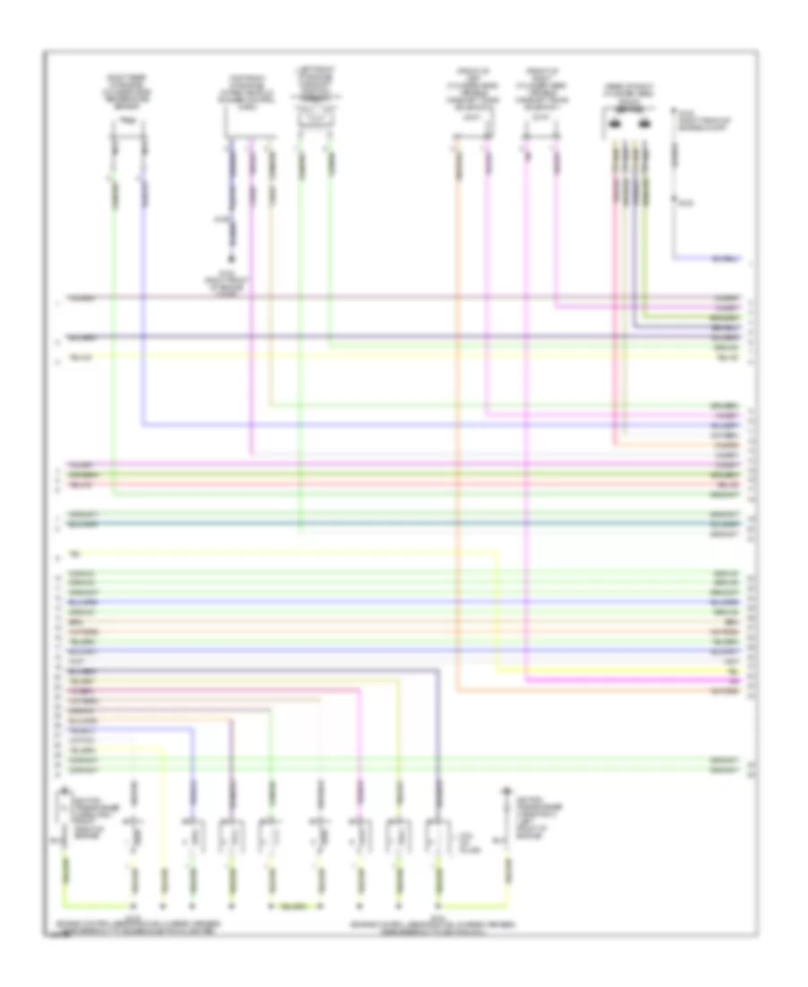
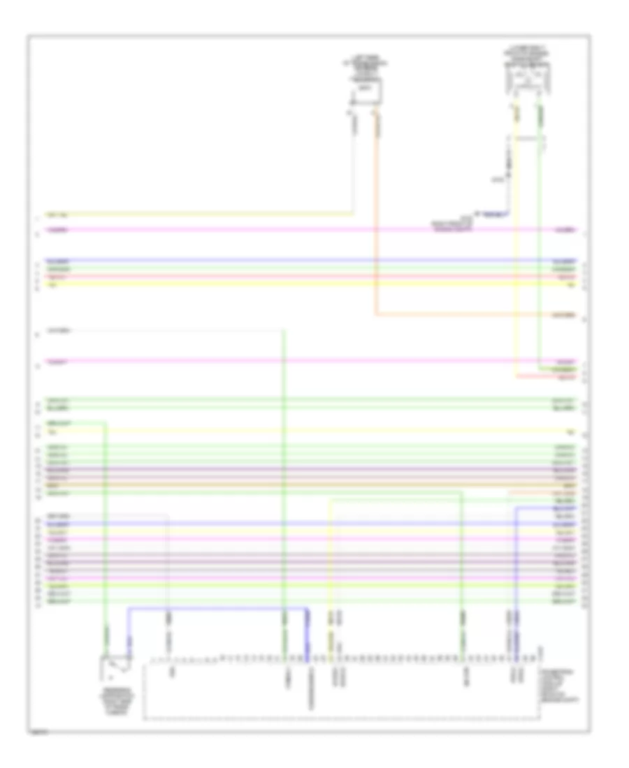
4.0L, Engine Performance Wiring Diagram (3 of 5) for Ford Mustang Shelby GT500 2010
 https://portal-diagnostov.com/license.html
Automotive Electricians Portal FZCO
Automotive Electricians Portal FZCO
https://portal-diagnostov.com/license.html
https://portal-diagnostov.com/license.html
Automotive Electricians Portal FZCO
Automotive Electricians Portal FZCOList of elements for 4.0L, Engine Performance Wiring Diagram (3 of 5) for Ford Mustang Shelby GT500 2010:
- (engine control sensor & fuel charge harness, near breakout to heated oxygen sensor 12) s106
- (left front of engine compt) a/c pressure transducer
- (left rear of transmission) output shaft speed (oss) sensor
- (top front of engine)
- (top left of transmission) turbine shaft speed (tss) sensor
- (top left side of transmission) intermediate shaft speed (iss) sensor
- (top rear of engine) ignition coil
- Automatic transmission
- Digital transmission range (dtr) sensor
- Electronic throttle control (etc) motor (throttle body)
- Engine coolant temperature (ect) sensor
- Fuel rail pressure & temperature sensor (top of engine)
- Heated positive crankcase ventilation (pcv) valve (top left side of engine)
- Nca
- Pressure sn
- Sig rtn
- Spark plugs
- Temp sn
- Throttle position (tp) sensor (throttle body assembly)
- Vref
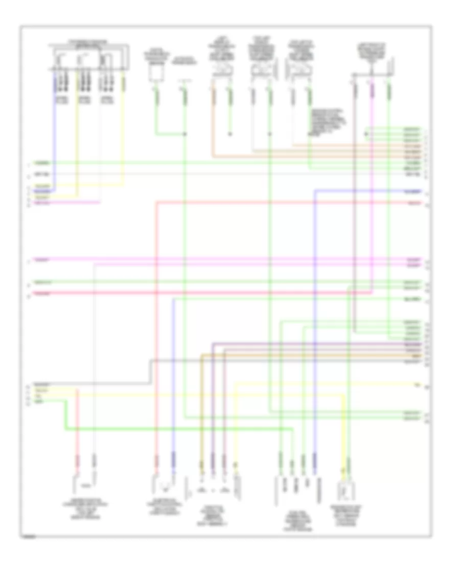
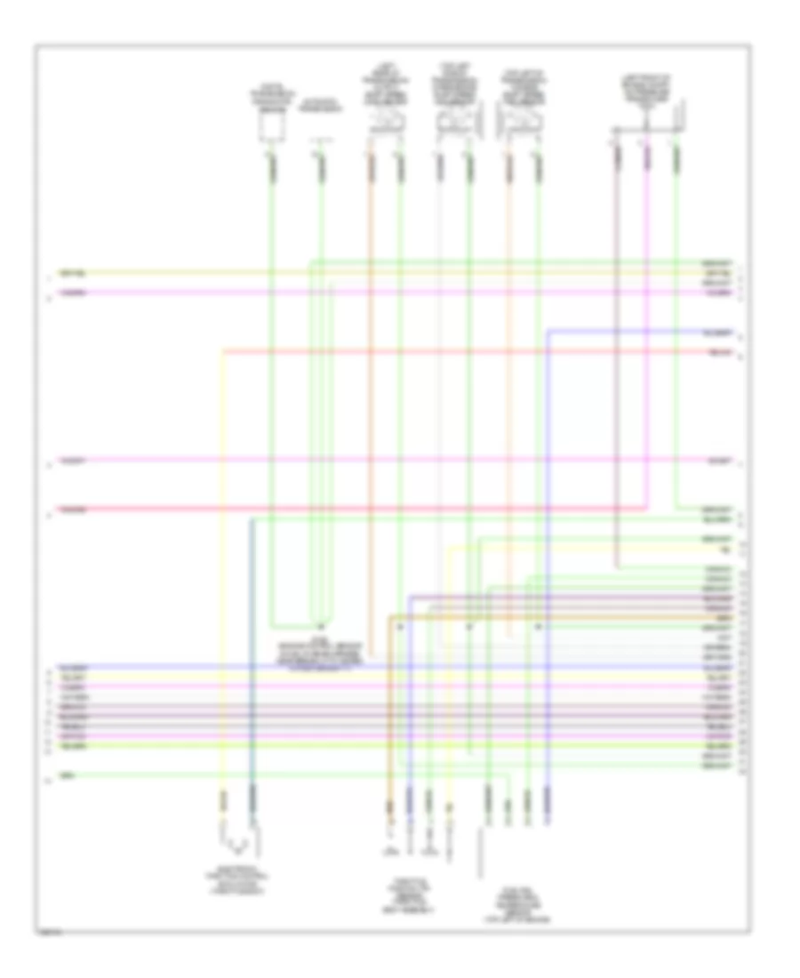
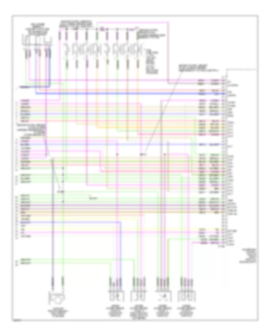
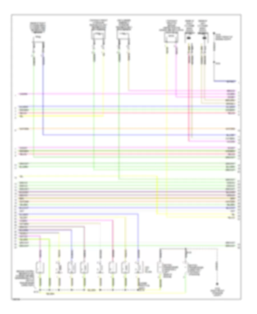
4.0L, Engine Performance Wiring Diagram (4 of 5) for Ford Mustang Shelby GT500 2010
 https://portal-diagnostov.com/license.html
Automotive Electricians Portal FZCO
Automotive Electricians Portal FZCO
https://portal-diagnostov.com/license.html
https://portal-diagnostov.com/license.html
Automotive Electricians Portal FZCO
Automotive Electricians Portal FZCOList of elements for 4.0L, Engine Performance Wiring Diagram (4 of 5) for Ford Mustang Shelby GT500 2010:
- (center front of engine) crankshaft position sensor
- (left side of transmission) digital transmission range (dtr) sensor
- Automatic transmission
- C175t
- Ce233
- Ce234
- Ce418
- Cet05
- Cet06
- Cet07
- Cet18
- Cet19
- Cet20
- Cet21
- Ho2s 12 rr
- Ho2s 22 lr
- Htr 12 rr
- Htr 22 lr
- Iss
- Nca
- Oss
- Pc a
- Pc b
- Pc c
- Powertrain control module (right front of engine compt)
- Re405
- Reverse switch
- Reversing lamps switch (m/t) (left side of trans- mission)
- S108
- Sig rtn a
- Ssa
- Ssb
- Ssc
- Ssd
- Tcc
- Tft
- Tr1
- Tr2
- Tr3a
- Tr4
- Tss
- Ve731
- Ve733
- Ve744
- Ve805
- Vet27
- Vet33
- Vet54
- Vet55
- Vet56
- Vet57
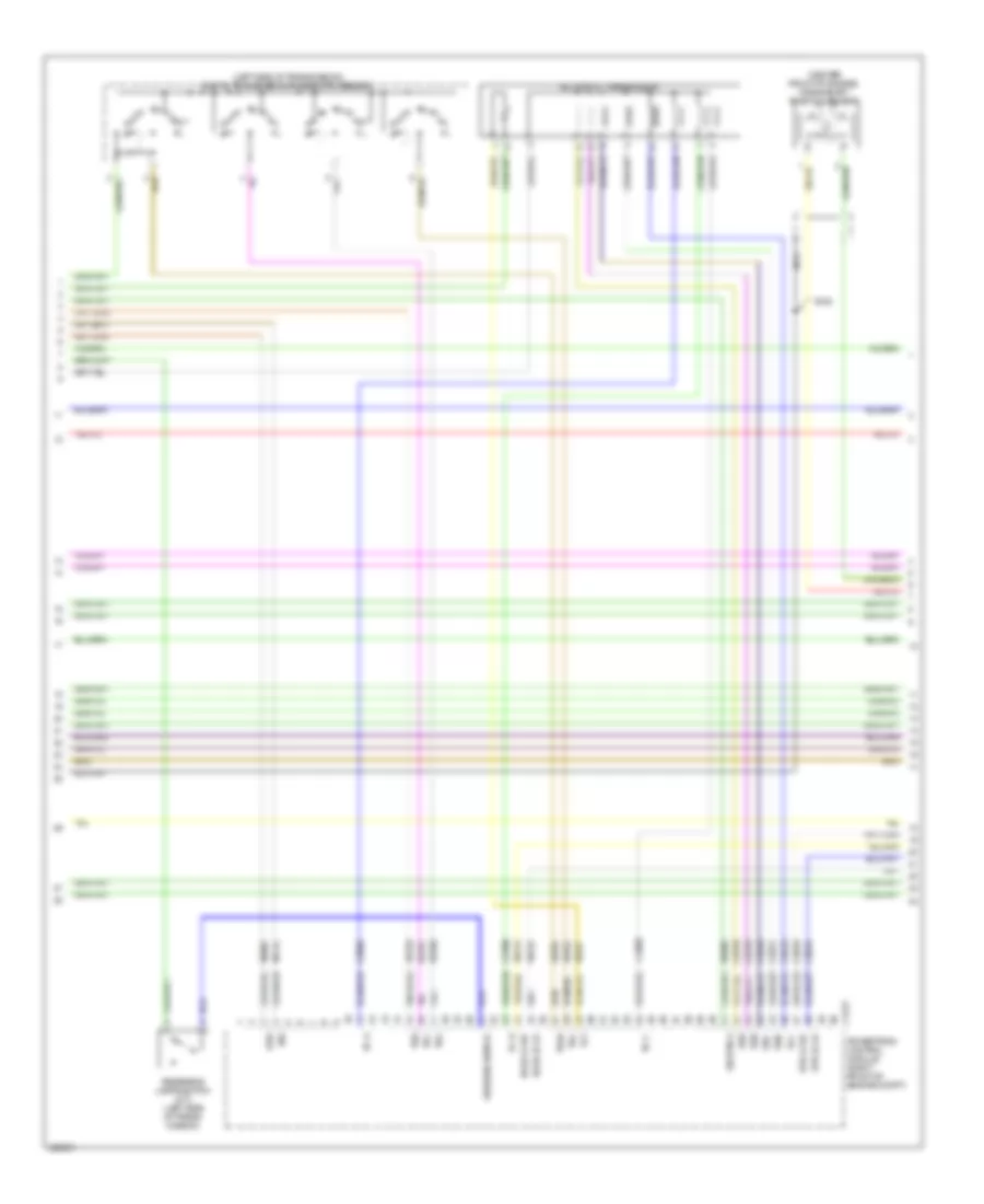
4.0L, Engine Performance Wiring Diagram (5 of 5) for Ford Mustang Shelby GT500 2010
 https://portal-diagnostov.com/license.html
Automotive Electricians Portal FZCO
Automotive Electricians Portal FZCO
https://portal-diagnostov.com/license.html
https://portal-diagnostov.com/license.html
Automotive Electricians Portal FZCO
Automotive Electricians Portal FZCOList of elements for 4.0L, Engine Performance Wiring Diagram (5 of 5) for Ford Mustang Shelby GT500 2010:
- (engine control sensor & fuel charge harness, near breakout to heated oxygen sensor 21) s101
- (engine control sensor & fuel charge harness, near breakout to turbine shaft speed sensor)
- (right side of engine compt) mass air flow/intake air temperature (maf/iat) sensor
- (top of engine) knock sensor
- C175e
- Camshaft position sensor (center front of engine)
- Cbb49
- Ce133
- Ce205
- Ce206
- Ce207
- Ce208
- Ce209
- Ce210
- Ce235
- Ce236
- Ce412
- Ce426
- Ce608
- Ckp+
- Ckp-
- Cmp
- Dpfe
- Dpfe sn
- Egr system module (top center of engine)
- Egr vacuum reg
- Etc ref
- Etc rtn
- Evr
- Fuel injectors (1, 2 & 3: top left side of engine) (4, 5 & 6: top right side of engine)
- Fuel rail press sens
- G102 (right front of engine compt)
- Heated oxygen sensor (ho2s) 11 (in exhaust manifold)
- Heated oxygen sensor (ho2s) 12 (right exhaust, after catalytic converter)
- Heated oxygen sensor (ho2s) 21 (on exhaust manifold)
- Heated oxygen sensor (ho2s) 22 (on exhaust manifold)
- Ho2s 11 rf
- Ho2s 21 lf
- Htr11 rf
- Htr21 lf
- Iat
- Inj pwrm
- Inj-1
- Inj-2
- Inj-3
- Inj-4
- Inj-5
- Inj-6
- Knock sensor 1+
- Knock sensor 1-
- Le134
- Le423
- Maf
- Mafrtn
- Map
- Map sensor
- Powertrain control module (right front of engine compt)
- Re134
- Re135
- Re320
- Re323
- Re405
- S102
- S103
- S107
- S108
- Sig rtn
- Tacm+
- Tacm-
- Tps1-ns
- Tps2-ps
- Ve706
- Ve711
- Ve713
- Ve727
- Ve735
- Ve737
- Ve740
- Ve801
- Ve804
- Ve807
- Ve818
- Ve819
- Vpwr
- Vref
4.6L
4.6L, Engine Performance Wiring Diagram (1 of 6) for Ford Mustang Shelby GT500 2010
 https://portal-diagnostov.com/license.html
Automotive Electricians Portal FZCO
Automotive Electricians Portal FZCO
https://portal-diagnostov.com/license.html
https://portal-diagnostov.com/license.html
Automotive Electricians Portal FZCO
Automotive Electricians Portal FZCOList of elements for 4.6L, Engine Performance Wiring Diagram (1 of 6) for Ford Mustang Shelby GT500 2010:
- (body main harness, near breakout to c192)
- (body main harness, near breakout to powertrain control module)
- (clutch pedal bracket) clutch pedal position switch
- (clutch pedal support) clutch pedal cruise control deactivator switch
- (left
- (left side of dash) cruise control deactivation switch
- (right front of engine compt) g103
- Accelerator pedal position sensor (left side of dash)
- Accr
- Acpt
- Air conditioning/ heater system
- App
- App2
- App3
- Apprtn
- Apprtn2
- Appvref
- Appvref2
- Battery junction box (bjb) (right side of engine compt)
- Bpp
- Bps
- C175b
- Canv
- Case gnd
- Cbb45
- Cbb47
- Ccb08
- Cdb08
- Cdc10
- Cdc12
- Ce114
- Ce302
- Ce509
- Ce904
- Ce905
- Cet34
- Cet40
- Ch302
- Cls09
- Clutch deact sw man trns ftpref
- Computer data lines system
- Cpp
- Cruise control system
- Evap canister purge valve (left side of engine compt)
- Evap canister vent control solenoid (left rear of vehicle)
- Exterior lights system
- Feps
- Fp control
- Fp monitor
- Front of engine compt) g104
- Ftp
- Fuel tank pressure (ftp) sensor (on fuel tank)
- Fuse 10a
- Fuse 15a
- Fuse 30a
- Fuse 5a
- G102 (right front of engine compt)
- Gd119
- Generator com
- Hot at all times
- Hot in start or run
- Hs can +
- Hs can -
- Ispr
- Kapwr
- Le136
- Le137
- Le230
- Od cancel sw sig
- Pcm power relay
- Pcm rc
- Powertrain control module (right front of engine compt)
- Pspsw
- Pwrgnd
- Re136
- Re137
- Res08
- S113
- S115
- S116
- S120
- S123
- S124
- S134
- Sbb23
- Sccs
- Sccs return
- Shift interlock system
- Start enable
- Starter motor req
- Starting/charging system
- Vdb04
- Vdb05
- Ve225
- Ve518
- Ve701
- Ve702
- Ve703
- Ve922
- Ves10
- Vh433
- Vpwr1
4.6L, Engine Performance Wiring Diagram (2 of 6) for Ford Mustang Shelby GT500 2010
 https://portal-diagnostov.com/license.html
Automotive Electricians Portal FZCO
Automotive Electricians Portal FZCO
https://portal-diagnostov.com/license.html
https://portal-diagnostov.com/license.html
Automotive Electricians Portal FZCO
Automotive Electricians Portal FZCOList of elements for 4.6L, Engine Performance Wiring Diagram (2 of 6) for Ford Mustang Shelby GT500 2010:
- (body main harness, near breakout to powertrain control module)
- (dash panel to headlight junction harness, near breakout to g100) s135
- Battery junction box (bjb) (right side of engine compt)
- C175e
- Cdc15
- Ce238
- Ce303
- Ce304
- Ce305
- Ce306
- Ce307
- Ce308
- Ce309
- Ce310
- Ce420
- Cec01
- Cec02
- Cooling fans system
- Cop1a
- Cop2d
- Cop3b
- Cop4g
- Cop5f
- Cop6e
- Cop7c
- Cop8h
- Evapcp
- Fp ctrl
- Fp monitor
- Fp power
- Fp rtn
- Frts
- Fuel pump driver module (rear of luggage compt)
- Fuel pump relay
- Fuel tank unit
- Fuse 15a
- G100 (right front of engine compt)
- G400 (left rear of luggage compt)
- Gd109
- Generator mon
- Gnd
- Hfc
- Hot at all times
- Hot in start or run
- Inertia fuel shutoff switch
- Instrument cluster system
- Lfc
- Nca
- Pcm power diode
- Pcvhc
- Powertrain control module (right front of engine compt)
- S112
- S122
- S407
- Starting/charging
- System
- Transmission shift selector
- Ve728
- Vpwr
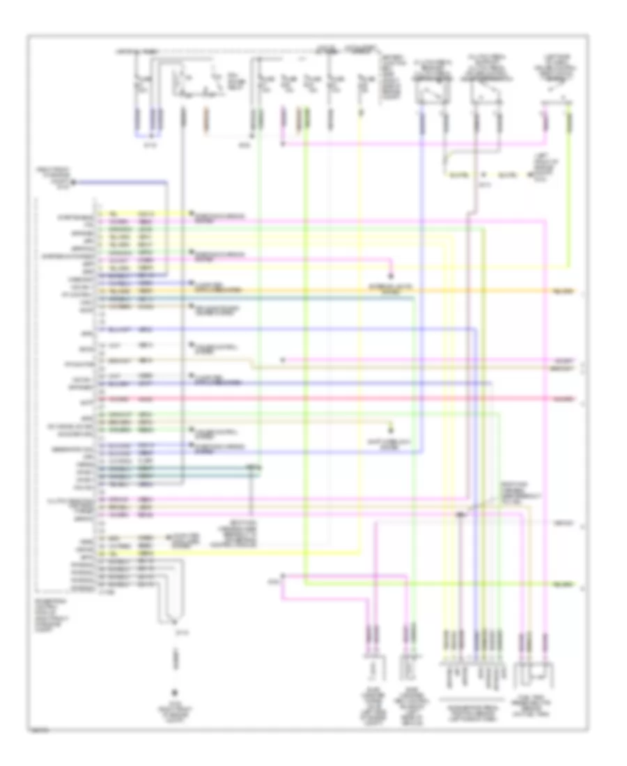
4.6L, Engine Performance Wiring Diagram (3 of 6) for Ford Mustang Shelby GT500 2010
 https://portal-diagnostov.com/license.html
Automotive Electricians Portal FZCO
Automotive Electricians Portal FZCO
https://portal-diagnostov.com/license.html
https://portal-diagnostov.com/license.html
Automotive Electricians Portal FZCO
Automotive Electricians Portal FZCOList of elements for 4.6L, Engine Performance Wiring Diagram (3 of 6) for Ford Mustang Shelby GT500 2010:
- (left front of engine compt) a/c pressure transducer
- (left rear of transmission) output shaft speed (oss) sensor
- (top left of transmission) turbine shaft speed (tss) sensor
- (top left side of transmission) intermediate shaft speed (iss) sensor
- Automatic transmission
- Digital transmission range (dtr) sensor
- Electronic throttle control (etc) motor (throttle body)
- Fuel rail pressure & temperature sensor (top left of engine)
- S106 (engine control sensor & fuel charge harness, near breakout to heated oxygen sensor 11)
- Throttle position (tp) sensor (throttle body assembly)
4.6L, Engine Performance Wiring Diagram (4 of 6) for Ford Mustang Shelby GT500 2010
 https://portal-diagnostov.com/license.html
Automotive Electricians Portal FZCO
Automotive Electricians Portal FZCO
https://portal-diagnostov.com/license.html
https://portal-diagnostov.com/license.html
Automotive Electricians Portal FZCO
Automotive Electricians Portal FZCOList of elements for 4.6L, Engine Performance Wiring Diagram (4 of 6) for Ford Mustang Shelby GT500 2010:
- (center front of engine) crankshaft position sensor
- (left side of transmission) digital transmission range (dtr) sensor
- Automatic transmission
- C175t
- Ce233
- Ce234
- Ce418
- Cet05
- Cet06
- Cet07
- Cet18
- Cet19
- Cet20
- Cet21
- Cet47
- G102 (right front of engine compt)
- Ho2s12
- Ho2s22
- Htr12
- Htr22
- Iss
- Nca
- Oss
- Pc a
- Pc b
- Pc c
- Powertrain control module (right front of engine compt)
- Re405
- Reverse switch
- Reversing lamps switch (m/t) (left side of trans- mission)
- S108
- Sig rtn
- Ssa
- Ssb
- Ssc
- Ssd
- Tcc
- Tft
- Tr1
- Tr2
- Tr3a
- Tr4
- Tss
- Ve731
- Ve733
- Ve744
- Ve805
- Vet27
- Vet33
- Vet54
- Vet55
- Vet56
- Vet57
4.6L, Engine Performance Wiring Diagram (5 of 6) for Ford Mustang Shelby GT500 2010
 https://portal-diagnostov.com/license.html
Automotive Electricians Portal FZCO
Automotive Electricians Portal FZCO
https://portal-diagnostov.com/license.html
https://portal-diagnostov.com/license.html
Automotive Electricians Portal FZCO
Automotive Electricians Portal FZCOList of elements for 4.6L, Engine Performance Wiring Diagram (5 of 6) for Ford Mustang Shelby GT500 2010:
- (engine control sensor & fuel charge harness, near breakout to ignition coil)
- (front of left cylinder head) variable camshaft timing solenoid 2
- (front of right cylinder head) variable camshaft timing solenoid 1
- (left front of engine) camshaft position sensor 2
- (rear of right cylinder head) knock sensor
- (right rear of engine) cylinder head temperature sensor
- (top front of engine) intake manifold runner control (imrc)
- Cbb49
- Ce918
- Coil on plugs
- G102 (right front of engine compt)
- Gd119
- Ignition transformer capacitor 1 (right front of engine)
- Ignition transformer capacitor 2 (left front of engine)
- Nca
- S104
- S108
- S119 (engine control sensor & fuel charge harness, near breakout to bussed electrical center)
4.6L, Engine Performance Wiring Diagram (6 of 6) for Ford Mustang Shelby GT500 2010
 https://portal-diagnostov.com/license.html
Automotive Electricians Portal FZCO
Automotive Electricians Portal FZCO
https://portal-diagnostov.com/license.html
https://portal-diagnostov.com/license.html
Automotive Electricians Portal FZCO
Automotive Electricians Portal FZCOList of elements for 4.6L, Engine Performance Wiring Diagram (6 of 6) for Ford Mustang Shelby GT500 2010:
- (air cleaner assembly) mass air flow/intake air temperature (maf/iat) sensor
- (engine control sensor & fuel charge harness, near breakout to c134)
- (engine control sensor & fuel charge harness, near breakout to fuel injector 4)
- (engine control sensor & fuel charge harness, near breakout to heated oxygen sensor 12)
- C175e
- Camshaft position sensor 1 (right front of engine)
- Ce205
- Ce206
- Ce207
- Ce208
- Ce209
- Ce210
- Ce211
- Ce212
- Ce235
- Ce236
- Ce412
- Ce421
- Ce422
- Ce426
- Ce608
- Ce918
- Cht
- Ckp+
- Ckp-
- Cmp
- Cmp2
- Etc ref
- Etc rtn
- Frps
- Fuel injectors (1, 2 & 3: top left side of engine) (4, 5, 6. 7 & 8: top right side of engine)
- Heated oxygen sensor (ho2s) 11 (in exhaust manifold)
- Heated oxygen sensor (ho2s) 12 (right exhaust, after catalytic converter)
- Heated oxygen sensor (ho2s) 21 (on exhaust manifold)
- Heated oxygen sensor (ho2s) 22 (on exhaust manifold)
- Ho2s11
- Ho2s21
- Htr11
- Htr21
- Iat
- Imrc
- Inj-1
- Inj-2
- Inj-3
- Inj-4
- Inj-5
- Inj-6
- Inj-7
- Inj-8
- Inj-pwrm
- Ks1+
- Ks1-
- Ks2+
- Ks2-
- Le134
- Le423
- Maf
- Mafrtn
- Powertrain control module (right front of engine compt)
- Re134
- Re135
- Re320
- Re323
- Re324
- Re405
- S101
- S102
- S103
- S107
- S109
- Sig rtn
- Tacm+
- Tacm-
- Tps1-ns
- Tps2-ps
- Vct1
- Vct2
- Ve706
- Ve707
- Ve711
- Ve712
- Ve727
- Ve735
- Ve737
- Ve740
- Ve801
- Ve802
- Ve807
- Ve818
- Ve819
- Vref
5.4L SUPERCHARGED
5.4L Supercharged, Engine Performance Wiring Diagram (1 of 6) for Ford Mustang Shelby GT500 2010
 https://portal-diagnostov.com/license.html
Automotive Electricians Portal FZCO
Automotive Electricians Portal FZCO
https://portal-diagnostov.com/license.html
https://portal-diagnostov.com/license.html
Automotive Electricians Portal FZCO
Automotive Electricians Portal FZCOList of elements for 5.4L Supercharged, Engine Performance Wiring Diagram (1 of 6) for Ford Mustang Shelby GT500 2010:
- (body main harness, near breakout to c192)
- (body main harness, near breakout to powertrain control module)
- (clutch pedal bracket) clutch pedal position switch
- (clutch pedal support) clutch pedal cruise control deactivator switch
- (left
- (left side of dash) cruise control deactivation switch
- (right front of engine compt) g103
- Accelerator pedal position sensor (left side of dash)
- Accr
- Acpt
- Air conditioning/ heater system
- App
- App2
- App3
- Apprtn
- Apprtn2
- Appvref
- Appvref2
- Battery junction box (bjb) (right side of engine compt)
- Bpp
- Bps
- C175b
- Canv
- Case gnd
- Cbb45
- Cbb47
- Ccb08
- Cdb08
- Cdc10
- Cdc12
- Ce114
- Ce302
- Ce509
- Ce904
- Ce905
- Cet34
- Cet40
- Ch302
- Cls09
- Clutch deact sw man trns ftpref
- Computer data lines system
- Cpp
- Cruise control system
- Evap canister purge valve (left side of engine compt)
- Evap canister vent control solenoid (left rear of vehicle)
- Exterior lights system
- Feps
- Fp control
- Fp monitor
- Front of engine compt) g104
- Ftp
- Fuel tank pressure (ftp) sensor (on fuel tank)
- Fuse 10a
- Fuse 15a
- Fuse 30a
- Fuse 5a
- G102 (right front of engine compt)
- Gd119
- Generator com
- Hot at all times
- Hot in start or run
- Hs can +
- Hs can -
- Isp-r
- Kapwr
- Le136
- Le137
- Le230
- Od cancel sw sig
- Pcm power relay
- Pcm rc
- Powertrain control module (right front of engine compt)
- Pspsw
- Pwrgnd
- Re136
- Re137
- Res08
- S113
- S115
- S116
- S120
- S123
- S124
- S134
- Sbb23
- Sccs
- Sccs return
- Shift interlock system
- Start enable
- Starter motor req
- Starting/charging system
- Vdb04
- Vdb05
- Ve225
- Ve518
- Ve701
- Ve702
- Ve703
- Ve922
- Ves10
- Vh433
- Vpwr1
5.4L Supercharged, Engine Performance Wiring Diagram (2 of 6) for Ford Mustang Shelby GT500 2010
 https://portal-diagnostov.com/license.html
Automotive Electricians Portal FZCO
Automotive Electricians Portal FZCO
https://portal-diagnostov.com/license.html
https://portal-diagnostov.com/license.html
Automotive Electricians Portal FZCO
Automotive Electricians Portal FZCOList of elements for 5.4L Supercharged, Engine Performance Wiring Diagram (2 of 6) for Ford Mustang Shelby GT500 2010:
- (body main harness, near breakout to g204)
- (body main harness, near breakout to g400) s417
- (dash panel to headlight junction harness, near breakout to g100) s135
- Battery junction box (bjb) (right side of engine compt)
- C175e
- Cdc15
- Ce238
- Ce303
- Ce304
- Ce305
- Ce306
- Ce307
- Ce308
- Ce309
- Ce310
- Ce420
- Cec01
- Cec02
- Charge air cooler pump relay
- Cooling fans system
- Cop1a
- Cop2d
- Cop3b
- Cop4g
- Cop5f
- Cop6e
- Cop7c
- Cop8h
- Ect
- Evapcp
- Fp ctrl
- Fp monitor
- Fp power
- Fp rtn
- Frts
- Fuel pump module
- Fuel pump relay
- Fuel pump relay 2
- Fuse 10a
- Fuse 15a
- Fuse 5a
- G100 (right front of engine compt)
- G400 (left rear of luggage compt)
- Gd109
- Generator mon
- Gnd
- Hfc
- Hot at all times
- Hot in start or run
- Inertia fuel shutoff switch
- Instrument cluster system
- Lfc
- Pcm power diode
- Pcvhc
- Powertrain control module (right front of engine compt)
- Primary fuel pump driver module
- S112
- S125
- S221
- S407
- Starting/charging
- System
- Ve716
- Ve728
- Vpwr
5.4L Supercharged, Engine Performance Wiring Diagram (3 of 6) for Ford Mustang Shelby GT500 2010
 https://portal-diagnostov.com/license.html
Automotive Electricians Portal FZCO
Automotive Electricians Portal FZCO
https://portal-diagnostov.com/license.html
https://portal-diagnostov.com/license.html
Automotive Electricians Portal FZCO
Automotive Electricians Portal FZCOList of elements for 5.4L Supercharged, Engine Performance Wiring Diagram (3 of 6) for Ford Mustang Shelby GT500 2010:
- (battery junction box) charge air cooler (cac) pump
- (dash panel to headlight junction harness, near breakout to right headlight) s112
- (left front of engine compt) a/c pressure transducer
- (left rear of transmission) output shaft speed (oss) sensor
- Electronic throttle control (etc) motor (throttle body)
- Fp ctrl
- Fp monitor
- Fp rtn
- Fuel rail pressure & temperature sensor (top right of engine)
- G100 (right front of engine compt)
- G403 (right rear of luggage compt)
- Gnd
- S106 (engine control sensor & fuel charge harness, near breakout to heated oxygen sensor 11)
- S415 (body main harness, near breakout to g403)
- Secondary fuel pump driver module
- Throttle position (tp) sensor (throttle body assembly)
- Vpwr
5.4L Supercharged, Engine Performance Wiring Diagram (4 of 6) for Ford Mustang Shelby GT500 2010
 https://portal-diagnostov.com/license.html
Automotive Electricians Portal FZCO
Automotive Electricians Portal FZCO
https://portal-diagnostov.com/license.html
https://portal-diagnostov.com/license.html
Automotive Electricians Portal FZCO
Automotive Electricians Portal FZCOList of elements for 5.4L Supercharged, Engine Performance Wiring Diagram (4 of 6) for Ford Mustang Shelby GT500 2010:
- (left rear of transmission) reverse lockout solenoid
- (lower right front of engine) crankshaft position sensor
- C175t
- Ce233
- Ce234
- Cet47
- Fp mon 2
- G102 (right front of engine compt)
- Ho2s 22
- Ho2s12
- Htr12
- Htr22
- Nca
- Oss
- Powertrain control module (right front of engine compt)
- Re405
- Reverse switch
- Reversing lamps switch (right side of trans- mission)
- S108
- Sig rtn
- Ve521
- Ve731
- Ve733
- Ve805
5.4L Supercharged, Engine Performance Wiring Diagram (5 of 6) for Ford Mustang Shelby GT500 2010
 https://portal-diagnostov.com/license.html
Automotive Electricians Portal FZCO
Automotive Electricians Portal FZCO
https://portal-diagnostov.com/license.html
https://portal-diagnostov.com/license.html
Automotive Electricians Portal FZCO
Automotive Electricians Portal FZCOList of elements for 5.4L Supercharged, Engine Performance Wiring Diagram (5 of 6) for Ford Mustang Shelby GT500 2010:
- (air cleaner assembly) intake air temperature 2 (iat2) sensor
- (engine control sensor & fuel charge harness, near breakout to ignition transformer capacitor 1)
- (rear of left cylinder bank) knock sensor 2
- (rear of right cylinder bank) cylinder head temperature sensor
- (rear of right cylinder bank) knock sensor 1
- (top right front of engine) engine coolant temperature (ect) sensor
- (top right front of engine) heated positive crankcase ventilation (pcv) valve
- (under throttle body)
- Coil on plugs
- G100 (right front of engine compt)
- G102 (right front of engine compt)
- Ignition transformer capacitor 1 (top right of engine)
- Ignition transformer capacitor 2 (left rear of engine)
- Nca
- S108
- S119
5.4L Supercharged, Engine Performance Wiring Diagram (6 of 6) for Ford Mustang Shelby GT500 2010
 https://portal-diagnostov.com/license.html
Automotive Electricians Portal FZCO
Automotive Electricians Portal FZCO
https://portal-diagnostov.com/license.html
https://portal-diagnostov.com/license.html
Automotive Electricians Portal FZCO
Automotive Electricians Portal FZCOList of elements for 5.4L Supercharged, Engine Performance Wiring Diagram (6 of 6) for Ford Mustang Shelby GT500 2010:
- (air cleaner assembly) mass air flow/intake air temperature (maf/iat) sensor
- (engine control sensor & fuel charge harness, near breakout to cylinder head temperature sensor)
- (engine control sensor & fuel charge harness, near breakout to ignition transformer capacitor 1)
- C175e
- Cac relay control
- Camshaft position sensor 1 (left front of engine)
- Cbb49
- Ce133
- Ce205
- Ce206
- Ce207
- Ce208
- Ce209
- Ce210
- Ce211
- Ce212
- Ce235
- Ce236
- Ce328
- Ce412
- Ce422
- Ce426
- Ce608
- Ce918
- Cht
- Ckp+
- Ckp-
- Cmp
- Dpfe
- Dpfe sens sn
- Egr system module (top center of engine)
- Egr vacuum reg
- Etc ref
- Etc rtn
- Evr
- Frps
- Fuel injectors (1, 2, 3, 4 & 7: top right of engine) (5, 6 & 8: top right of engine)
- Heated oxygen sensor (ho2s) 11 (in exhaust manifold)
- Heated oxygen sensor (ho2s) 12 (right exhaust, after catalytic converter)
- Heated oxygen sensor (ho2s) 21 (on exhaust manifold)
- Heated oxygen sensor (ho2s) 22 (on exhaust manifold)
- Ho2s11
- Ho2s21
- Htr11
- Htr21
- Iat
- Iat2
- Inj pwrm
- Inj-1
- Inj-2
- Inj-3
- Inj-4
- Inj-5
- Inj-6
- Inj-7
- Inj-8
- Ks2+
- Ks2-
- Ksi+
- Ksi-
- Le134
- Le423
- Maf
- Mafrtn
- Map
- Map sensor
- Pcvhc
- Powertrain control module (right front of engine compt)
- Re134
- Re135
- Re320
- Re323
- Re324
- Re405
- Rs lockout
- S101
- S102
- S103
- S107
- S109
- Sig rtn
- Tacm+
- Tacm-
- Tps1-ns
- Tps2-ps
- Ve706
- Ve711
- Ve712
- Ve713
- Ve727
- Ve735
- Ve737
- Ve740
- Ve751
- Ve801
- Ve802
- Ve804
- Ve818
- Ve819
- Vpwr
- Vref

 Čeština
 Dansk
Dansk Deutsch
 Ελληνικά
 English
 English
 Español
 Suomi
Suomi Français
 Français
 עברית
עברית Hrvatski
 Magyar
 Italiano
 日本語
日本語 한국어
한국어 Nederlands
 Polski
 Português
 Português
 Română
 Русский
 Slovenčina
 Slovenščina
 Svenska
 Türkçe
