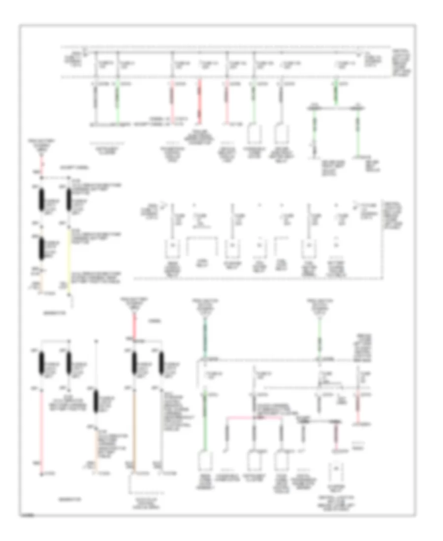
POWER DISTRIBUTION
Power Distribution Wiring Diagram (1 of 4) for Ford Excursion 2005
 https://portal-diagnostov.com/license.html
Automotive Electricians Portal FZCO
Automotive Electricians Portal FZCO
https://portal-diagnostov.com/license.html
https://portal-diagnostov.com/license.html
Automotive Electricians Portal FZCO
Automotive Electricians Portal FZCO
List of elements for Power Distribution Wiring Diagram (1 of 4) for Ford Excursion 2005:
- (behind lower left side of dash) central junction box (cjb)
- (in back-up light switch to rear light feed harness, in breakout for auxiliary relay box 3) s199
- (in eng ctrl sens harn, near breakout for c1045) s163
- (in engine control sensor harness, at breakout for battery junction box) s103
- (in main harness, near breakout for auxiliary relay box 1) s249
- (in main harness, near breakout for data link connector) s242
- (in main harness, near breakout for instrument cluster) s228
- (in main harness, near breakout for restraints control module) (w/ electronic shift on the fly) s230
- (in main harness, near breakout to brake pedal position switch) s214
- (not used)
- 30a
- A/c clutch relay
- Abs control module
- Accessory delay relay
- Adjustable pedal switch (w/o memory)
- Auxiliary a/c relay
- Auxiliary relay box 1 (behind center od dash)
- Auxiliary relay box 3 (w/ electronic shift on the fly) (diesel: left side of engine compt) (except diesel: at left rear side of engine compt)
- Auxiliary relay box 4
- Auxiliary relay box 4 (at left rear side of engine compt)
- Auxiliary relay box 5 (at left rear side of engine compt)
- Auxiliary relay box 5 (diesel) (at left rear side of engine compt)
- Battery
- Battery ii (diesel)
- Brake pedal position switch
- C- pillar power point (at base of left "c" pillar)
- C197b
- C202a
- C205a
- C2113b
- C218a
- C228b
- C270a
- C270b
- C270d
- C270e
- C270g
- C270h
- C270i
- C270j
- C270k
- C270m
- C290a
- C341c
- Central junction box (cjb) (behind lower left side of dash)
- Console power point (w/ rear audio controls) (center floor pan)
- Data link connector (dlc)
- Daytime running lamps resistor
- Diesel
- Driver seat module (w/ memory)
- Driver side front seat adjust switch (w/ memory)
- Dvd player
- Electronic automatic temperature control (eatc) module
- Except diesel
- Exterior rear view mirror switch
- Four-wheel drive control module (w/ electronic shift on the fly)
- From a fuse 10 (diagram 1 of 4)
- From b fuse 16 (diagram 1 of 4)
- Front cigar lighter
- Fuel injector control module (ficm) power relay
- Fuse
- Fuse 1 15a
- Fuse 108 40a
- Fuse 10a
- Fuse 11 20a
- Fuse 111 30a
- Fuse 12 20a
- Fuse 13 5a
- Fuse 14 15a
- Fuse 15a
- Fuse 17 15a
- Fuse 18 20a
- Fuse 19 10a
- Fuse 2 20a
- Fuse 20 10a
- Fuse 21 25a
- Fuse 3 20a
- Fuse 34 10a
- Fuse 4 20a
- Fuse 5 20a
- Fuse 6 20a
- Fuse 602 60a
- Fuse 7 30a
- G201 (behind left side of dash)
- G202 (behind left side of dash)
- G301 (at left ``c" pillar)
- G403 (at right ``d" pillar)
- Indicator flasher relay
- Instru- ment panel power point
- Junction block
- Left turn trailer tow relay
- Main light switch
- Multi- function switch
- Nca
- Passenger side front seat adjust switch
- Passive anti-theft transceiver module
- Radio
- Rear integrated control panel (w/ rear audio controls)
- Rear power point (after "c" pillar)
- Rear wiper motor assembly
- Red
- Right turn trailer tow relay
- S1000 (in battery output harness, in breakout to left fender junction block)
- S1002 (diesel) (in eng control harness, under battery junction box)
- S290
- S300
- S316 (w/ memory) (in body main harness, near grommet on left side of vehicle floor)
- S324
- Starter motor (lower right rear of engine)
- To fuse (diagram 2 of 4)
- To fuse 108 (diagram 1 of 4)
- To fuse 12 (diagram 1 of 4)
- To fusible links (diagram 2 of 4)
- Transfer case high to low relay
- Transfer case low to high relay
- Vehicle security module (vsm)
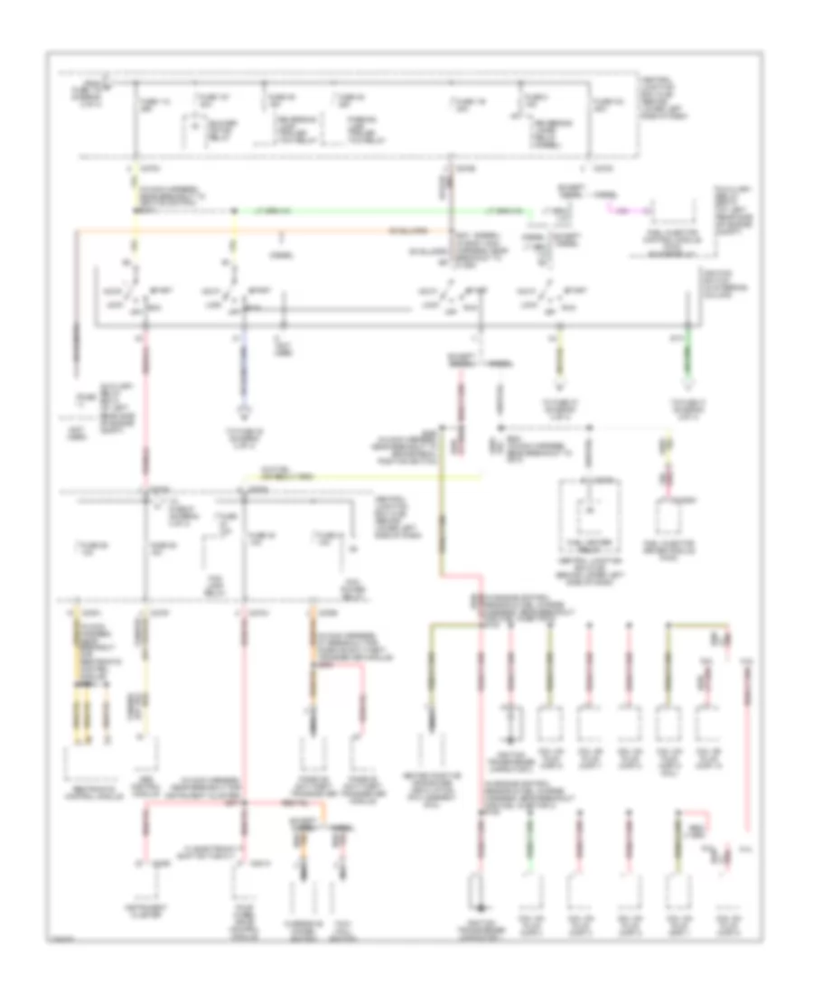
Power Distribution Wiring Diagram (2 of 4) for Ford Excursion 2005
 https://portal-diagnostov.com/license.html
Automotive Electricians Portal FZCO
Automotive Electricians Portal FZCO
https://portal-diagnostov.com/license.html
https://portal-diagnostov.com/license.html
Automotive Electricians Portal FZCO
Automotive Electricians Portal FZCOList of elements for Power Distribution Wiring Diagram (2 of 4) for Ford Excursion 2005:
- (behind lower left side of dash) central junction box (cjb)
- (diesel)
- (except diesel)
- (in main harness, at breakout for instrument cluster) s254
- (not used)
- Battery charge trailer tow relay
- C102a
- C102c
- C1273a
- C1273b
- C1381a
- C175
- C2113b
- C220c
- C270a
- C270b
- C270c
- C270e
- C270f
- C270g
- C270h
- C270i
- C270j
- C270k
- C270m
- C281a
- C290a
- C341b
- Central junction box (cjb) (behind lower left side of dash)
- Diesel
- Digital transmission range (dtr) sensor
- Driver seat module
- Driver side front heated seat relay
- Driver side front seat adjust switch
- Except diesel
- Four- wheel drive control module
- From battery (diagram 1 of 4)
- From c fuse 111 (diagram 1 of 4)
- From d fuse 112 (diagram 2 of 4)
- From ignition switch (diagram 3 of 4)
- Fuel heater relay (diesel)
- Fuel pump relay
- Fuse 101 30a
- Fuse 102 30a
- Fuse 106 30a
- Fuse 109 30a
- Fuse 112 30a
- Fuse 15a
- Fuse 20a
- Fuse 30a
- Fuse 33 15a
- Fuse 35 10a
- Fuse 36 10a
- Fuse 40a
- Fuse 41 10a
- Fuse 48 10a
- Fuse 5a
- Fusible link e
- Generator
- Glow plug control module (gpcm)
- Horn relay
- Instrument cluster
- Nca
- Pcm power relay
- Powertrain control module (pcm)
- Radio
- Rear window defrost relay
- Rear wiper motor assembly
- Red
- Red s125
- S125 (in alternator rectifier harness, battery positive)
- S126 (in alternator rectifier harness, battery positive)
- S147 (in engine control sensor & fuel charge harness, near breakout for glow plug control module)
- S149
- S149 (in alternator rectifier harness, near positive battery cable)
- Starter relay
- To fuse (diagram 3 of 4)
- To fuse 104 (diagram 2 of 4)
- Trailer electronic brake control connector
- Vehicle security module (vsm)
- W/ memory
- W/o memory
- Windshield wiper motor
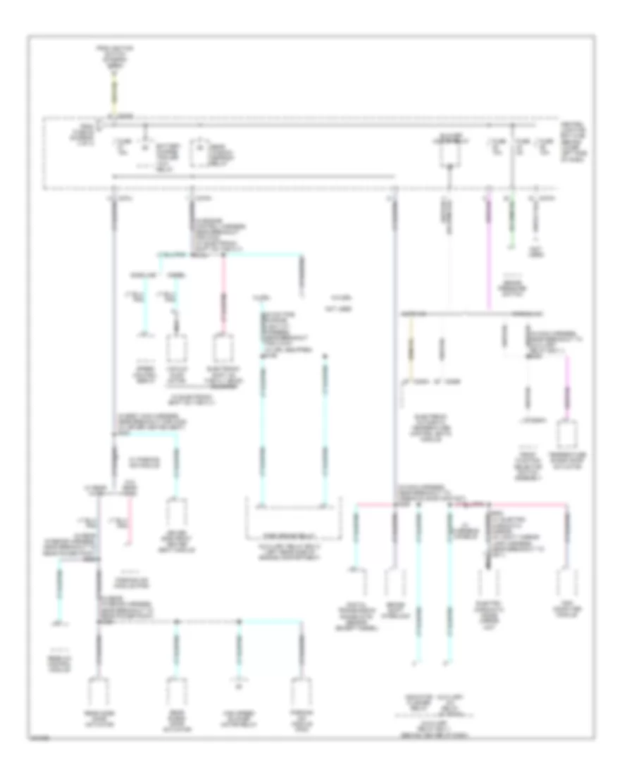
Power Distribution Wiring Diagram (3 of 4) for Ford Excursion 2005
 https://portal-diagnostov.com/license.html
Automotive Electricians Portal FZCO
Automotive Electricians Portal FZCO
https://portal-diagnostov.com/license.html
https://portal-diagnostov.com/license.html
Automotive Electricians Portal FZCO
Automotive Electricians Portal FZCOList of elements for Power Distribution Wiring Diagram (3 of 4) for Ford Excursion 2005:
- (diesel)
- (in engine control sensor & fuel charge harness, near breakout for fuel injector 3) s135
- (in engine control sensor & fuel charge harness, near breakout for fuel injector 6) s130
- (in main harness, at breakout for passive anti-theft transceiver module) s209
- (in main harness, near breakout for instrument cluster) s271
- (in main harness, near breakout to ignition switch) s210
- (not used)
- 5.4l
- 6.8l
- Abs control module
- Acc
- Auxiliary relay box 5 (at left rear side of engine compt)
- Blower motor relay
- C1388c
- C220c
- C270a
- C270b
- C270c
- C270e
- C270f
- C281a
- Central junction box (cjb) (behind lower left side of dash)
- Coil on plug (cop) 1
- Coil on plug (cop) 10
- Coil on plug (cop) 2
- Coil on plug (cop) 3
- Coil on plug (cop) 4
- Coil on plug (cop) 5
- Coil on plug (cop) 6
- Coil on plug (cop) 7
- Coil on plug (cop) 8
- Coil on plug (cop) 9 (6.8l)
- Diesel
- Except diesel
- Fog lamp relay
- Four wheel drive control module
- From e fuse 115 (diagram 2 of 4)
- Fuel heater relay
- Fuel injector control module (ficm) power relay
- Fuel injector driver module (ficm)
- Fuse
- Fuse 103 50a
- Fuse 107 40a
- Fuse 10a
- Fuse 110 50a
- Fuse 116 30a
- Fuse 25 10a
- Fuse 26 10a
- Fuse 38 20a
- Fuse 39 15a
- Fuse 44 10a
- Fuse 45 10a
- Fuse 8 15a
- Heated positive crankcase ventilation (pcv) element (6.8l)
- Ignition switch (in steering column)
- Ignition transformer capacitor 1
- Ignition transformer capacitor 2
- Instrument cluster
- Lock
- Nca
- Off
- Overdrive cancel switch
- Parking lamp trailer tow relay
- Passive anti-theft transceiver
- Passive anti-theft transceiver module
- Pcm power relay
- Red/
- Restraints control module
- Reversing lamp trailer tow relay
- Reversing lamps relay (diesel)
- Run
- S224 (in main harness, near breakout to c210)
- S231 (in body main harness, near breakout to c1393)
- S258 (in main harness, near breakout to brake pedal position switch)
- Sta
- Start
- To fuse 27 (diagram 4 of 4)
- To fuse 31 (diagram 2 of 4)
- To fuse 48 (diagram 2 of 4)
- Tow/ haul switch
- W/ electronic shift on the fly
Power Distribution Wiring Diagram (4 of 4) for Ford Excursion 2005
 https://portal-diagnostov.com/license.html
Automotive Electricians Portal FZCO
Automotive Electricians Portal FZCO
https://portal-diagnostov.com/license.html
https://portal-diagnostov.com/license.html
Automotive Electricians Portal FZCO
Automotive Electricians Portal FZCOList of elements for Power Distribution Wiring Diagram (4 of 4) for Ford Excursion 2005:
- (in body main harness, near breakout for c340) (w/ driver heated seat) s303
- (in engine control harness, near breakout for g100) (w/ electronic shift on the fly) s124
- (in main harness, near breakout to airbag sliding contact) s206
- (in main harness, near breakout to auxiliary relay box 1) s235
- (in rear interior harness, near breakout to rear power point) s320
- (in rear interior harness, near breakout to rear power point) s322
- (not used)
- (w/ electro- chromatic mirror) (in vanity mirror lamp harness, near breakout to c911)
- (w/ electronic shift on the fly)
- Auto a/c
- Auxiliary a/c relay (w/ eatc)
- Auxiliary relay box 1 (behind center of dash)
- Auxiliary relay box 2 (left rear side of engine compartment)
- Battery charge trailer tow relay
- Blower motor relay
- Brake pressure switch
- Brake shift interlock
- C228a
- C228b
- C270a
- C270c
- C270h
- C294a
- Central junction box (cjb) (behind lower left side of dash)
- Diesel
- Digital transmission range (dtr) sensor (except diesel)
- Driver side front heated seat module
- Electro- chromatic inside mirror unit
- Electronic automatic temperature control (eatc) module
- Electronic shift on the fly (ecof) solenoid
- From ignition switch (diagram 3 of 4)
- From j fuse 25 (diagram 3 of 4)
- Front function selector switch assembly
- Fuse 10a
- Fuse 15a
- Fuse 2a
- Gasoline
- High speed blower motor relay
- Indicator flasher relay
- Manual a/c
- Nca
- Not used
- Park brake relay
- Parking aid module (pam)
- Rear a/c control module
- Rear blend door actuator
- Rear mode door actuator
- Rear window defrost relay
- Running light kit harness, near breakout for c1047) (w/ drl equipped) s198
- Speed control servo
- Temperature blend door actuator
- Trip computer module
- Vacuum pump motor
- W/ drl
- W/ overhead console
- W/ parking aid module
- W/ rear hvac
- W/o drl
- W/o rear hvac

 Čeština
 Dansk
Dansk Deutsch
 Ελληνικά
 English
 English
 Español
 Suomi
Suomi Français
 Français
 עברית
עברית Hrvatski
 Magyar
 Italiano
 日本語
日本語 한국어
한국어 Nederlands
 Polski
 Português
 Português
 Română
 Русский
 Slovenčina
 Slovenščina
 Svenska
 Türkçe
