POWER DISTRIBUTION
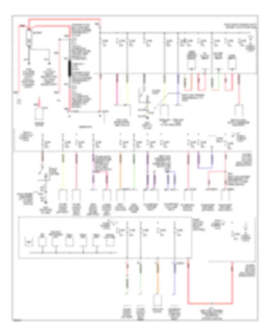
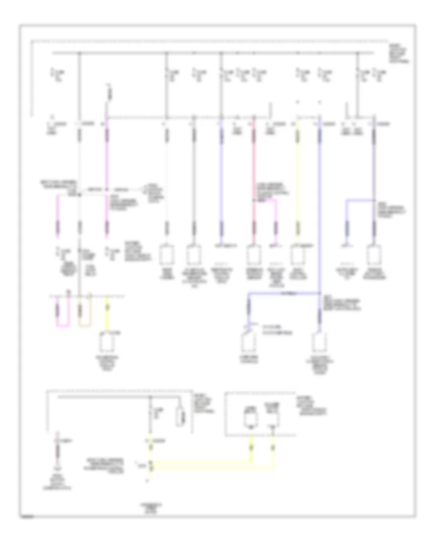
Power Distribution Wiring Diagram (1 of 5) for Ford Mustang Shelby GT500 2010
 https://portal-diagnostov.com/license.html
Automotive Electricians Portal FZCO
Automotive Electricians Portal FZCO
https://portal-diagnostov.com/license.html
https://portal-diagnostov.com/license.html
Automotive Electricians Portal FZCO
Automotive Electricians Portal FZCO
List of elements for Power Distribution Wiring Diagram (1 of 5) for Ford Mustang Shelby GT500 2010:
- (4.0l) s117
- (4.0l) s118
- (4.6l: right rear of engine compt)
- (body main harness, near breakout to c919)
- (body main harness, near breakout to left front wheel speed sensor)
- (body main harness, near breakout to powertrain control module)
- (body main harness,near breakout to passenger side scuff plate light)
- (main harness, near break- out to audio control module)
- (power seats harness, near breakout to driver side front seat adjust switch) s302
- (right side of engine compt)
- (right side of engine compt) battery junction box (bjb)
- (starter motor relay & battery ground harness, near breakout to g106)
- (w/ hid headlamps)
- 3rd row seat enable (fet)
- 4.0l
- 4.6l/ 5.4l
- A/c clutch relay
- Accessory protocol interface module (apim)
- Anti-lock brake system (abs) module
- Battery
- Battery junction box (bjb)
- Blower motor relay
- Body control module b
- Bsi (fet)
- C102a
- C102b
- C175b
- C197a
- C2993a
- C2994a
- C4368a
- Convertible top lower relay
- Convertible top raise relay
- From fuse 24 a (diagram 1 of 5)
- From fuse 33 b (diagram 1 of 5)
- Front cigar lighter
- Fuse 10a
- Fuse 15a
- Fuse 20a
- Fuse 30a
- Fuse 40a
- Fuse 80a
- Fuselink a (8 ga black)
- G106 (4.0l: rear of engine compt) (4.6l/5.4l: right rear of engine compt)
- G107 (4.0l: right side of engine compt)
- G200 (right side
- G203 (right "a"
- Generator
- Headlamp, left
- Headlamp, right
- Keypad illum (fet)
- Lumbar control switch, left front
- Of dash)
- Pillar)
- Power point
- Power window motor, left front
- Power window motor, left rear
- Power window motor, right front
- Power window motor, right rear
- Powertrain control module
- Rear window defrost relay
- Red
- S110 (4.6l/5.4l) (alternator rectifier system harness, near breakout to c133/battery)
- S111 (4.6l/5.4l) (in alternator rectifier system harness, near breakout to battery)
- S114
- S200
- S223
- S307
- S319
- Seat adjust switch, driver side front
- Seat control switch, passenger side front
- Smart junction box (sjb) (right kick panel)
- Start relay
- Starter motor
- Stoplamp switch
- Sub- woofer amplifier, rear
- Subwoofer amplifier, left front
- Subwoofer amplifier, right front
- To fuse 16 (diagram 1 of 5)
- To fuse 21 (diagram 2 of 5)
- To fuse 34 (diagram 1 of 5)
- To fuse 6 (diagram 3 of 5)
- Tpms 1 (fet)
- Tpms 2 (fet)
- Tpms 3 (fet)
- Vbat
- Wiper relay
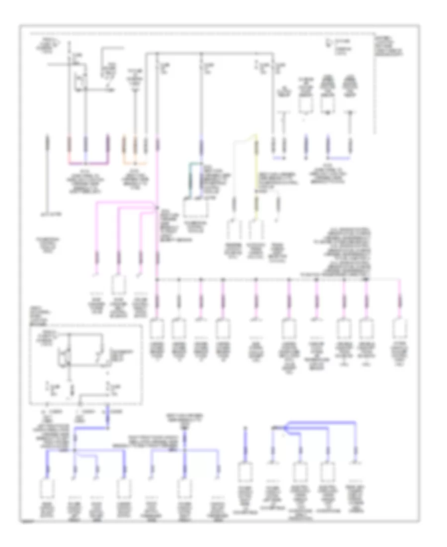
Power Distribution Wiring Diagram (2 of 5) for Ford Mustang Shelby GT500 2010
 https://portal-diagnostov.com/license.html
Automotive Electricians Portal FZCO
Automotive Electricians Portal FZCO
https://portal-diagnostov.com/license.html
https://portal-diagnostov.com/license.html
Automotive Electricians Portal FZCO
Automotive Electricians Portal FZCOList of elements for Power Distribution Wiring Diagram (2 of 5) for Ford Mustang Shelby GT500 2010:
- (4.0l: engine control sensor & fuel charge harness, near breakout to heated oxygen sensor #21) (4.6l: engine control sensor & fuel charge harness, near breakout to fuel injector 4) (5.4l: engine control sensor & fuel charge harness, near breakout to ignition transformer capacitor 1) s101
- (4.6l)
- (body main harness, near breakout to c192)
- (body main harness, near breakout to c919)
- (body main harness, near breakout to front impact severity sensor)
- (body main harness, near breakout to powertrain control module)
- (dash panel to headlight junction harness, near breakout to g100)
- (dash panel to headlight junction harness, near breakout to right headlight)
- (not used)
- (right kick panel) smart junction box (sjb)
- (right side of engine compt)
- (w/ convertible)
- Ac clutch relay
- Accessory delay relay
- Automatic trans- mission (4.0l/4.6l)
- Battery junction box (bjb)
- Breakout to powertrain control module)
- C175b
- C2280a
- C2280d
- Charge air cooler pump relay
- Cruise control deacti- vation switch
- Door lock switch, driver side
- Door lock switch, passenger side
- Egr system module (except 4.6l)
- Electro- chromatic inside mirror unit (w/ microphone)
- Electro- chromatic inside mirror unit (w/o microphone, early production)
- Evap canister purge valve
- Evap canister vent control solenoid
- From fuse 1 c (diagram 1 of 5)
- From fuse 27 j (diagram 4 of 5)
- Fuse 15a
- Fuse 30a
- Fuse 5a
- Heated oxygen sensor (ho2s)
- Heated positive crankcase ventilation (pcv) valve (except 4.6l)
- High speed engine cooling fan relay
- Intake manifold runner control (imrc)
- Left front door window regulator harness, near breakout to left front power window motor)
- Low speed engine cooling fan relay
- Mass air flow/ intake air temperature (maf/iat) sensor
- Master window adjust switch
- Micro
- Pcm power relay
- Power window motor, left front
- Power window motor, left rear
- Power window motor, right front
- Power window motor, right rear
- Powertrain control module
- Powertrain control module (pcm)
- Rear view camera display mirror (w/ rear view camera)
- Rear window adjust switch
- Reverse lockout solenoid (5.4l)
- Right front door window regulator harness, near breakout to right front speaker)
- S116
- S120
- S122
- S124
- S125
- S234
- S500
- S600
- To fuse (diagram 3 of 5)
- Trans- mission shift selector (4.0l/4.6l)
- Variable camshaft timing solenoid
- Variable camshaft timing solenoid (4.6l)
- Window adjust switch, passenger side
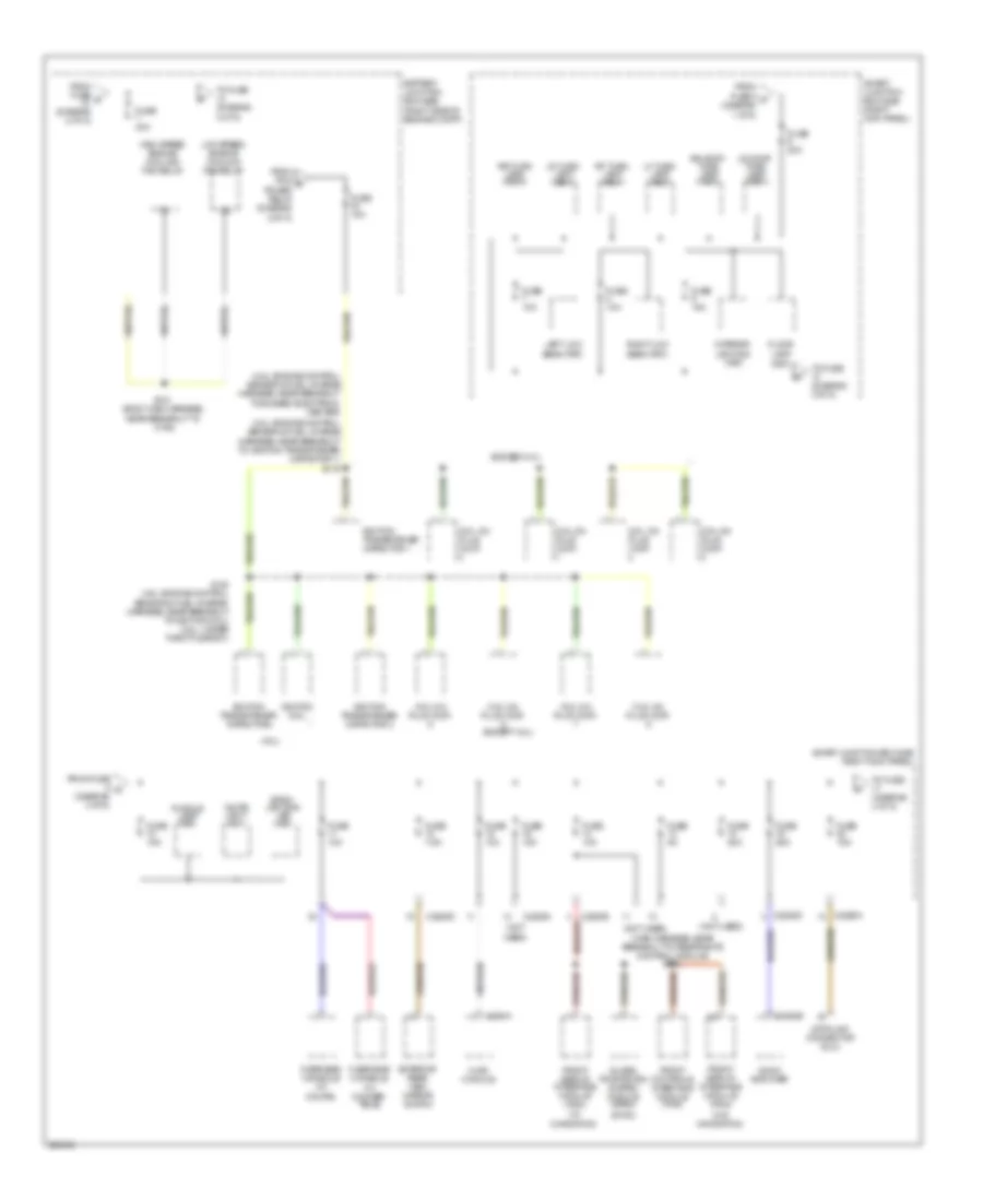
Power Distribution Wiring Diagram (3 of 5) for Ford Mustang Shelby GT500 2010
 https://portal-diagnostov.com/license.html
Automotive Electricians Portal FZCO
Automotive Electricians Portal FZCO
https://portal-diagnostov.com/license.html
https://portal-diagnostov.com/license.html
Automotive Electricians Portal FZCO
Automotive Electricians Portal FZCOList of elements for Power Distribution Wiring Diagram (3 of 5) for Ford Mustang Shelby GT500 2010:
- (4.0l)
- (4.6l: engine control sensor & fuel charge harness, near breakout to bussed electrical center)
- (5.4l: engine control sensor & fuel charge harness, near breakout to ignition transformer capacitor 1)
- (body main harness, near breakout to c192)
- (except 4.0l)
- (fet)
- (main harness, near breakout to restraints control module)
- (not used)
- (right side of engine compt)
- (sync)
- (w/ navigation)
- (w/o navigation)
- Audio amplifier
- Back- lighting led (fet)
- Battery junction box (bjb)
- C2280a
- C2280b
- C2280d
- C294a
- C4364b
- Coil on plug (cop)
- Coil on plug (cop) (except 4.0l)
- Data link connector (dlc)
- Exterior rear view mirror switch
- Floor lamp
- From fuse 5 m (diagram 1 of 5)
- From fuse d (diagram 2 of 5)
- From fuse g (diagram 3 of 5)
- From pcm e power relay (diagram 2 of 5)
- Front controls interface module (fcim)
- Front display interface module (fdim)
- Fuse 10a
- Fuse 15a
- Fuse 20a
- Fuse 25a
- Fuse 40a
- Fuse 5a
- Fuse 7.5a
- Global positioning system module (gpsm)
- High speed engine cooling fan relay
- Hvac module
- Ignition coil
- Ignition transformer capacitor
- Ignition transformer capacitor 1
- Ignition transformer capacitor 2
- Interior lighting (fet)
- Left low beam (fet)
- Lf turn lamp (fet)
- Low speed engine cooling fan relay
- Lr stop/ turn lamp (fet)
- Lr turn lamp (fet)
- Overhead console (w/ conver- tible)
- Overhead console (w/ coupe)
- Puddle lamp (fet)
- Rf turn lamp (fet)
- Right low beam (fet)
- Rr stop/ turn lamp (fet)
- Rr turn lamp (fet)
- S104 (4.6l: engine control sensor & fuel charge harness, near breakout to ignition coil) (5.4l: under throttle body)
- S119
- S121
- S232
- Smart junction box (sjb) (right kick panel)
- To fuse (diagram 3 of 5)
- To fuse (diagram 4 of 5)
- White light (fet)
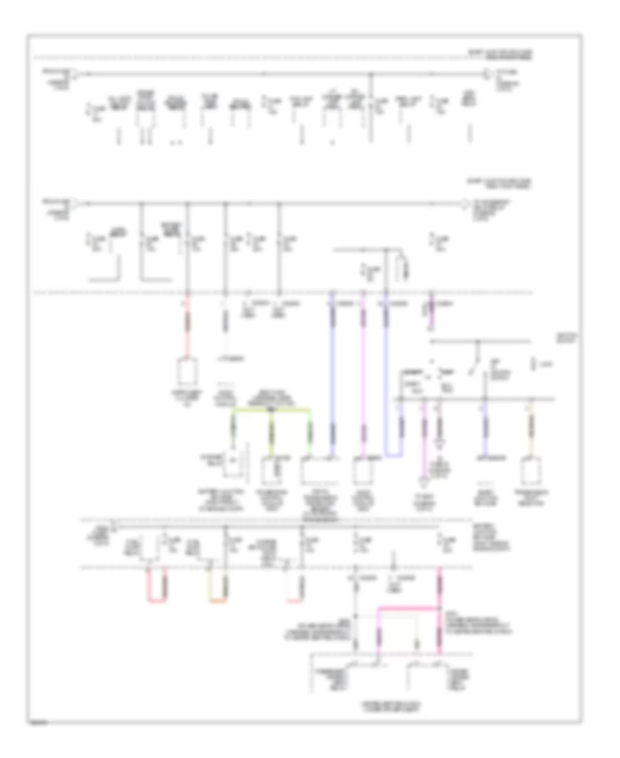
Power Distribution Wiring Diagram (4 of 5) for Ford Mustang Shelby GT500 2010
 https://portal-diagnostov.com/license.html
Automotive Electricians Portal FZCO
Automotive Electricians Portal FZCO
https://portal-diagnostov.com/license.html
https://portal-diagnostov.com/license.html
Automotive Electricians Portal FZCO
Automotive Electricians Portal FZCOList of elements for Power Distribution Wiring Diagram (4 of 5) for Ford Mustang Shelby GT500 2010:
- (5.4l)
- (body main harness, near breakout to c192) s131
- (diagram 5 of 5)
- (not used)
- (power seats wiring harness, near breakout to heated seat relay box)
- Acc/ run
- All lock/ unlock relay
- Audio control module
- Audio control module (acm)
- Battery junction box (bjb) (right front of engine compt)
- Battery junction box (bjb) (right side of engine compt)
- Battery saver relay
- C175b
- C2280a
- C2280b
- C2280d
- C2280e
- C290d
- Charge air cooler pump relay
- Digital transmission range (dir) sensor (w/ automatic transmission)
- Driver door unlock relay
- Driver heated seat relay
- Fog lamp relay
- From f fuse 7 (diagram 3 of 5)
- From fuse h (diagram 3 of 5)
- From fuse i (diagram 4 of 5)
- Fuel pump relay
- Fuse 10a
- Fuse 15a
- Fuse 20a
- Fuse 5a
- Heated seat relay box (under driver's seat)
- High beam relay
- Horn relay
- Ignition switch
- Instrument cluster (ic)
- Key in ignition switch
- Lh corner lamp (fet)
- Lock
- Micro
- Off
- Park lamp relay
- Passenger heated seat relay
- Powertrain control module (pcm)
- Pulse train (fet)
- Red
- Rh corner lamp (fet)
- Run
- S304
- S305
- Smart junction box (sjb)
- Smart junction box (sjb) (right kick panel)
- Start
- Start/
- Starter relay
- To accessory delay relay (diagram 2 of 5)
- To fuse (diagram 4 of 5)
- To fuse 45 (diagram 5 of 5)
- To s240
- Transmission shift selector
- Trunk rel (fet)
- Trunk release relay
Power Distribution Wiring Diagram (5 of 5) for Ford Mustang Shelby GT500 2010
 https://portal-diagnostov.com/license.html
Automotive Electricians Portal FZCO
Automotive Electricians Portal FZCO
https://portal-diagnostov.com/license.html
https://portal-diagnostov.com/license.html
Automotive Electricians Portal FZCO
Automotive Electricians Portal FZCOList of elements for Power Distribution Wiring Diagram (5 of 5) for Ford Mustang Shelby GT500 2010:
- (body main harness, near breakout to c192)
- (body main harness, near breakout to powertrain control module)
- (body main harness, near breakout to smart junction box)
- (main harness, near breakout to audio control module)
- (main harness, near breakout to c2205)
- (main harness, near breakout to g202)
- (not used)
- (right side of engine compt)
- (w/ convertible)
- (w/ coupe)
- Anti-lock brake system (abs) module
- Battery junction box (bjb)
- Battery junction box (sjb)
- Blower motor relay
- Body control module b
- C175b
- C2041a
- C2280a
- C2280b
- C2280d
- C2280e
- C4368a
- From ignition switch (diagram 4 of 5)
- Fuel pump relay
- Fuse 10a
- Fuse 5a
- Fuse 7.5a
- In-vehicle temperature sensor (w/ automatic a/c)
- Instrument cluster (ic)
- Micro
- Occupant classification sensor module (ocsm)
- Overhead console
- Passive anti-theft transceiver
- Pcm power diode
- Powertrain control module (pcm)
- Rear video camera
- Rear window defrost relay
- Restraints control module (rcm)
- S126
- S130
- S235
- S236
- S237
- S240
- Smart junction box (sjb) (right kick panel)
- Steering position sensor
- Windshield wiper motor
- Wiper relay

 Čeština
 Dansk
Dansk Deutsch
 Ελληνικά
 English
 English
 Español
 Suomi
Suomi Français
 Français
 עברית
עברית Hrvatski
 Magyar
 Italiano
 日本語
日本語 한국어
한국어 Nederlands
 Polski
 Português
 Português
 Română
 Русский
 Slovenčina
 Slovenščina
 Svenska
 Türkçe
