POWER DISTRIBUTION
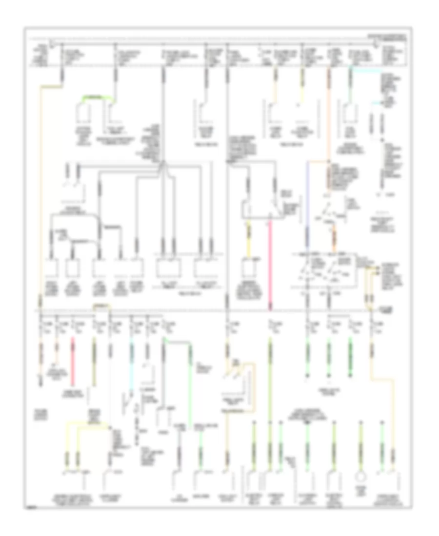
Power Distribution Wiring Diagram (1 of 3) for Ford Ranger Splash 1997
 https://portal-diagnostov.com/license.html
Automotive Electricians Portal FZCO
Automotive Electricians Portal FZCO
https://portal-diagnostov.com/license.html
https://portal-diagnostov.com/license.html
Automotive Electricians Portal FZCO
Automotive Electricians Portal FZCO
List of elements for Power Distribution Wiring Diagram (1 of 3) for Ford Ranger Splash 1997:
- (dash to headlamp harness, near break- out to engine compt fuse/ relay box) s136
- (dash to headlamp harness, near breakout to c135 & c136, left side of safety wall) s138
- (dash to headlamp harness, near breakout to ground g104, top center of left fender apron) s124
- (engine extention harn, near breakout to c114, left rear of engine) s1002
- (main harness, in break- out to ignition switch & shift lock actuator) s232
- (not used)
- 4 wheel anti- lock brake system (4wabs) main relay
- 4 wheel anti-lock brake system (4wabs) module
- A/c- heater control assembly
- A/t
- Acc
- Air bag diagnostic monitor
- Back-up lamp switch
- Battery
- Blend door actuator
- Blower motor relay
- Brake pressure switch
- C177
- C178
- C224
- C228
- C251
- C256
- C410
- Clutch pedal position (ccp) switch
- Daytime runing lamps (drl) module
- Digital transmission range (dtr) sensor
- Engine compartment fuse/relay box
- Flasher
- Fuse 10a
- Fuse 10a (4wabs)
- Fuse 15a
- Fuse 20a (rabs)
- Fuse 30a
- Fuse 7.5a
- Generator/ voltage regulator
- Generic electronic module (gem)/ central timer module (ctm)
- I/p fuse panel
- Ignition maxi fuse 14 50a
- Ignition switch
- Lock
- M/t
- Nca
- Off
- Passive de- activation (pad) module
- Power window relay
- Radio
- Rear anti- lock brake system (rabs) module
- Red
- Relay box #1
- Relay box #2
- Relay box #3
- Remote anti-theft personality (rap) module
- Run
- S126 (dash to headlamp harness, near breakout to left front park/turn lamp)
- S227 (main harness, near break- out to instrument cluster)
- S250 (main harness, near breakout to i/p fuse panel)
- Shift lock actuator
- Speed control servo/amplifier assembly
- Sta
- Start
- Starter interrupt relay
- Starter motor/ solenoid
- Starter relay
- To i/p fuse panel, fuse 15 (diagram 3 of 3)
- To i/p fuse/panel maxi fuse 13 (diagram 2 of 3)
- Trans- mission control switch (tcs)
- W/ anti- theft
- W/ pad
- W/o anti- theft
- W/o pad
- W/o rap w/ rap
- Washer pump relay
- Wind- shield wiper motor
- Wiper hi-lo relay
- Wiper run/ park relay
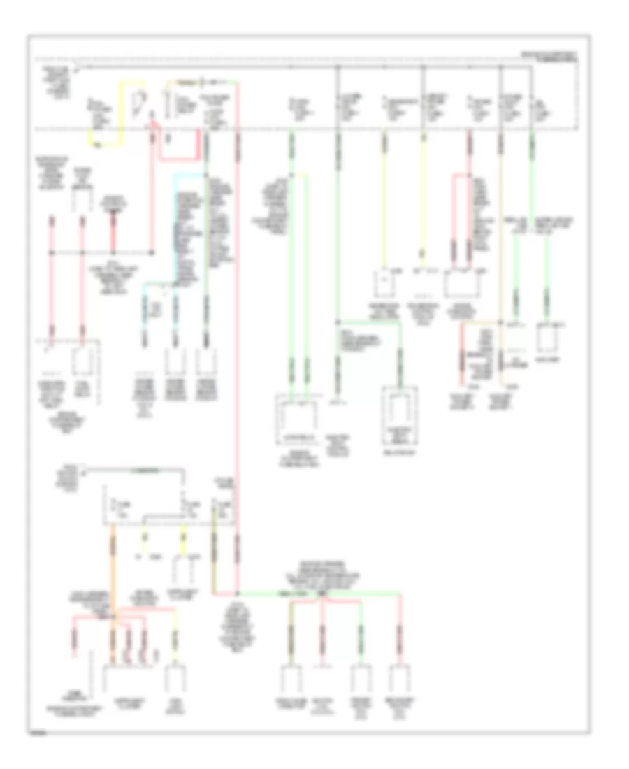
Power Distribution Wiring Diagram (2 of 3) for Ford Ranger Splash 1997
 https://portal-diagnostov.com/license.html
Automotive Electricians Portal FZCO
Automotive Electricians Portal FZCO
https://portal-diagnostov.com/license.html
https://portal-diagnostov.com/license.html
Automotive Electricians Portal FZCO
Automotive Electricians Portal FZCOList of elements for Power Distribution Wiring Diagram (2 of 3) for Ford Ranger Splash 1997:
- (main harness, near break- out to ignition tamper switch & clockspring assembly) s224
- (main harness, near breakout to ignition tamper switch & clockspring assembly) s222
- (main harness, near breakout to instrument cluster) s221
- 4wabs main relay
- 4wabs main relay maxi fuse 6 30a
- 4wabs pump motor relay
- 4wabs pump relay maxi fuse 5 30a
- All lock relay
- All unlock relay
- Amplifier
- Battery saver relay
- Blower motor maxi fuse 9 40a
- Blower motor relay
- Brake on/off (boo) switch
- C216
- C224
- C228
- C254
- C409
- C414
- Cd changer
- Cigar lighter
- Data link connector (dlc)
- Daytime running lamps (drl) module
- Dimmer switch
- Dome/ map light
- Driver's unlock relay
- Drl sys/fog lamps mini fuse 8 15a
- Electric shift control module
- Electric shift relay
- Engine compartment fuse/relay box
- Exterior lights system (main light switch or park lamps relay)
- Flash- to-pass switch
- Flasher
- Fog lamp relay
- From a
- Fuel pump relay
- Fuel sys/ anti-theft maxi fuse 3 20a
- Fuse (not used)
- Fuse 10a
- Fuse 15a
- Fuse 25a
- Fuse 7.5a
- G104 (top center of left fender apron)
- Generic electronic module (gem)/ central timer module (ctm)
- Glove box lamp & switch
- Harness near break- out to i/p fuse panel) s223
- Head
- Head- lamps maxi fuse 4 20a
- Headlights system
- I/p fuse panal maxi fuse 13 50a
- I/p fuse panel
- Ignition maxi fuse 14 (diagram 1 of 3)
- Instrument cluster
- Instrument illumination dimming module
- Interior lamp relay
- Left power bolster switch
- Left power lumbar switch
- Left seat control switch
- Main light switch
- Multi- function switch
- Nca
- Off
- Park
- Park lamps maxi fuse 8 20a
- Park lamps relay
- Pas
- Pnk
- Power lock/ window/seat maxi fuse 10 20a
- Power mirror switch
- Power window relay
- Rabs test connector
- Radio
- Red
- Regular cab w/ cd
- Relay box #1
- Relay box #2
- Relay box #3
- Remote anti- theft personality (rap) module
- Right power lumbar switch
- S209
- S219 (main harn, near breakout to radio)
- S302 (interior lamp harness, near breakout to right rear speaker)
- Super cab
- Super cab only
- To pcm power maxi fuse 2 (diagram 3 of 3)
- W/ premium sound
Power Distribution Wiring Diagram (3 of 3) for Ford Ranger Splash 1997
 https://portal-diagnostov.com/license.html
Automotive Electricians Portal FZCO
Automotive Electricians Portal FZCO
https://portal-diagnostov.com/license.html
https://portal-diagnostov.com/license.html
Automotive Electricians Portal FZCO
Automotive Electricians Portal FZCOList of elements for Power Distribution Wiring Diagram (3 of 3) for Ford Ranger Splash 1997:
- (engine harness, near breakout to: 2.3l, intake air temperature sensor; 3.0l, ignition coil; 4.0l, fuel injector #3) s101
- (main harness, near breakout to i/p fuse panel) s240
- 3.0l/ 4.0l only
- 4 wheel drive mini fuse 4 20a
- Air bag diagnostic monitor
- Air bag mini fuse 7 10a
- Amplifier
- Auxiliary power socket 1
- Auxiliary power socket 2
- C111
- C168
- C214
- C215
- C216
- C235
- C248
- C250
- C251
- C414
- Cd changer
- Cluster
- Electric shift control module
- Electric shift relay
- Engine compartment fuse/relay box
- Engine controls system
- Evaporative emissions (evap) canister purge solenoid
- From fuel c sys/anti- theft maxi fuse 3 (diagram 2 of 3)
- From ignition b
- Fuel pump relay
- Fuse 25a
- Fuse 7.5a
- Generator mini fuse 6 15a
- Generator/ voltage regulator
- Heated oxygen sensor (ho2s) #1
- Heated oxygen sensor (ho2s) #2
- Heated oxygen sensor (ho2s) #3 (4.0l & 3.0l only)
- Ho2s mini fuse 3 15a
- Horn maxi fuse 11 20a
- Horn relay
- I/p fuse panel
- Ignition coil (3.0l/4.0l)
- Instrument
- Instrument cluster
- Jbl mini fuse 1 20a
- Main light switch
- Memory power mini fuse 5 15a
- Nca
- Pcm power diode
- Pcm power maxi fuse 2 30a
- Pcm power relay
- Power point mini fuse 2 30a
- Powertrain control module (pcm)
- Primary ignition coil (2.3l)
- Purge flow (pf) sensor
- Rabs resistor
- Radio noise capacitor
- Red
- Regular cab w/ cd
- Relay box #1
- S109 (engine harness near break- out to: 2.3l, heated oxygen sensor #1; 4.0l & 3.0l, octane adjust shorting bar)
- S121 (dash to headlamp harness, near breakout to left headlamp)
- S134 (dash to headlamp harness, in breakout to engine compartment fuse relay box)
- S135 (dash to headlamp harness, in break- out to engine compartment fuse/relay panel)
- S200 (main harn, near break- out to ground g203, behind right cowl panel)
- S218 (main harness, near breakout to radio)
- S231 (main harn, near breakout to auxiliary power socket)
- Secondary ignition coil (2.3l)
- Super cab and regular cab w/o cd
- Switch (diagram 1 of 3)
- Wide open throttle a/c cut- off (wac) relay

 Čeština
 Dansk
Dansk Deutsch
 Ελληνικά
 English
 English
 Español
 Suomi
Suomi Français
 Français
 עברית
עברית Hrvatski
 Magyar
 Italiano
 日本語
日本語 한국어
한국어 Nederlands
 Polski
 Português
 Português
 Română
 Русский
 Slovenčina
 Slovenščina
 Svenska
 Türkçe
