ENGINE PERFORMANCE
3.6L
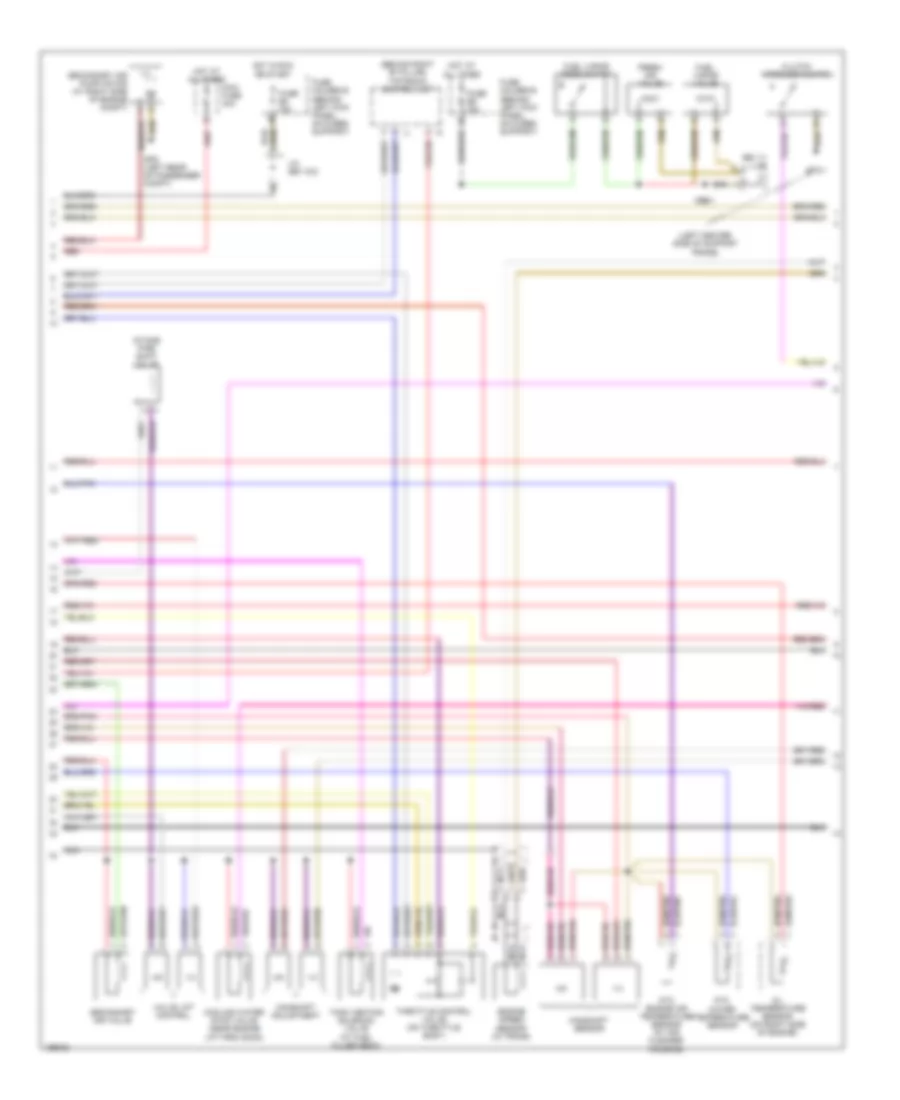
3.6L, Engine Performance Wiring Diagram, Early Production (1 of 3) for Porsche 911 GT3 2005
 https://portal-diagnostov.com/license.html
Automotive Electricians Portal FZCO
Automotive Electricians Portal FZCO
https://portal-diagnostov.com/license.html
https://portal-diagnostov.com/license.html
Automotive Electricians Portal FZCO
Automotive Electricians Portal FZCO
List of elements for 3.6L, Engine Performance Wiring Diagram, Early Production (1 of 3) for Porsche 911 GT3 2005:
- "w" lead
- (right rear of pass- enger compt)
- +5v
- Anti-theft system
- Before cat heat o2s1
- Before cat heat o2s2
- Before cat o2s 1 gnd
- Before cat o2s 1 sig
- Before cat o2s 2 gnd
- Before cat o2s 2 sig
- Behind cat heat o2s1
- Behind cat heat o2s2
- Behind cat o2s 1 gnd
- Behind cat o2s 1 sig
- Behind cat o2s 2 gnd
- Behind cat o2s 2 sig
- Camshaft sensor 1
- Camshaft sensor 2
- Can tiptronic high
- Can tiptronic low
- Electronic gnd
- Final stage gnd
- Fuel injectors
- Fuel pump ctrl unit
- Fuse c1 25a
- Fuse c2 30a
- Fuse holder c (behind left kick panel, on fuses support)
- Gp8 (left rear of pass- enger compt)
- Gp9
- Heated oxygen sensor 1 (1-3) (after catalytic converter)
- Heated oxygen sensor 1 (1-3) (before catalytic converter)
- Heated oxygen sensor 2 (4-6) (after catalytic converter)
- Heated oxygen sensor 2 (4-6) (before catalytic converter)
- Hfm +5v
- Hfm gnd
- Hfm signal
- Hot at all times
- Ignition/ injection/ oxygen sensor relay (on relay support 2)
- Inj 2/cyl 6
- Inj 4/cyl 4
- Inj 5/cyl 3
- Inj 6/cyl 5
- Injection gnd
- Intake pipe shift vlv
- J/c (bs 21/1)
- Lifting valve 1-3
- Lifting valve 4-6
- Mass airflow sensor (near air cleaner housing, in air duct)
- Mfi & di control unit (behind left rear seatwell)
- Mfi & di relay (on relay support 2)
- Mfi+di term. 87
- Nca
- Ntc eng temp sensor
- Ntc water
- P/n release
- Red
- Second air pump rly
- Second air valve
- Secondary air pump relay (on relay support 2)
- Sensors gnd
- Speed sensor shld
- Starting/ charging system, a/c system, cooling fans system, transmission controls system
- Tank venting valve
- Temp intake line
- Temp motor oil
- Term 15
- Term. 30
- Throttle valve +5v
- Throttle valve gnd
- Throttle valve sig
- Throttle vlv mtr (+)
- Throttle vlv mtr (-)
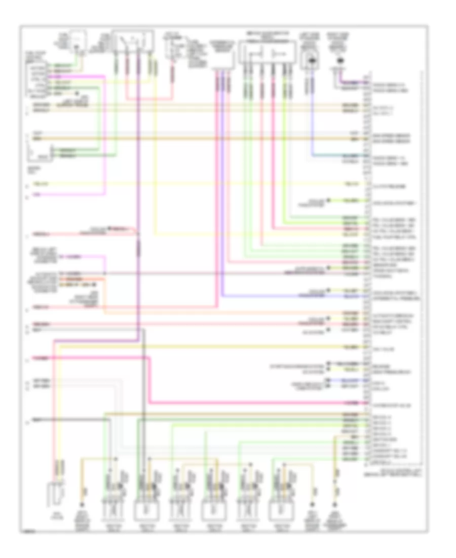
3.6L, Engine Performance Wiring Diagram, Early Production (2 of 3) for Porsche 911 GT3 2005
 https://portal-diagnostov.com/license.html
Automotive Electricians Portal FZCO
Automotive Electricians Portal FZCO
https://portal-diagnostov.com/license.html
https://portal-diagnostov.com/license.html
Automotive Electricians Portal FZCO
Automotive Electricians Portal FZCOList of elements for 3.6L, Engine Performance Wiring Diagram, Early Production (2 of 3) for Porsche 911 GT3 2005:
- (behind right "b" pillar) tiptronic control unit
- (bs 11) j/c
- (left center side of support frame)
- 1-3
- 4-6
- Camshaft adjustment
- Camshaft sensor
- Clutch interlock switch
- Cooling water stop valve (near engine lift provision)
- Engine speed sensor (in trans)
- Fresh air valve
- Fuel vapor reed switch
- Fuel vapor valve
- Fuse b8 15a
- Fuse e6 15a
- Fuse holder b (behind left kick panel, on fuses support)
- Fuse holder e (behind left kick panel, on fuses support)
- Gp3/1
- Gp8 (left rear of passenger compt)
- Hot at all times
- Hot in run or start
- Intake pipe shift valve
- J/c (bs 13/2)
- Maxi fuse 40a
- Nca
- Ntc engine air temperature sensor (at air cleaner housing)
- Ntc water temperature sensor
- Oil temperature sensor (on right side of engine)
- Red
- Secondary air pump motor (at right side of engine compt)
- Secondary air valve
- Tank venting solenoid valve (at fuel filler neck)
- Throttle control valve (on throttle body)
- Valve lift control
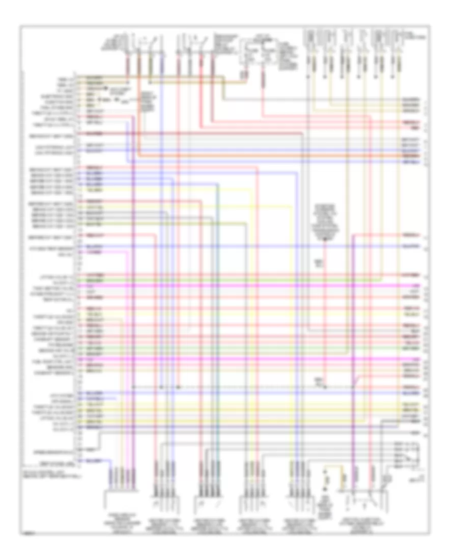
3.6L, Engine Performance Wiring Diagram, Early Production (3 of 3) for Porsche 911 GT3 2005
 https://portal-diagnostov.com/license.html
Automotive Electricians Portal FZCO
Automotive Electricians Portal FZCO
https://portal-diagnostov.com/license.html
https://portal-diagnostov.com/license.html
Automotive Electricians Portal FZCO
Automotive Electricians Portal FZCOList of elements for 3.6L, Engine Performance Wiring Diagram, Early Production (3 of 3) for Porsche 911 GT3 2005:
- (behind accelerator pedal) pedal value sensor
- (below left side of dash) diagnosis connector
- (left side of engine) knock sensor 1 (cyl 1-3)
- (right side of engine) knock sensor 2 (cyl 4-6)
- +5v pdl value sens 1
- +5v pdl value sens 2
- A/c relay
- A/c system
- Aav valve
- Automatic egr exam
- Automatic exhaust gas
- Camshaft adj 1-3
- Camshaft adj 4-6
- Can hi
- Can low
- Clutch release
- Computer data lines system
- Cooling blwr stage 1
- Cooling blwr stage 2
- Cooling fans system
- Crash shut-down
- Ctrl
- Ctrl in
- Differential pressure
- Differential pressure sensor
- Ekpsm coil
- Eng compt control
- Eng speed sensor
- Fuel pump (in fuel tank)
- Fuel pump control unit
- Fuel pump relay (on relay support 1)
- Fuel pump relay ctrl
- Fuse c4 30a
- Fuse holder c (behind left kick panel, on fuses support)
- Gp10 (right rear of engine compt)
- Gp11 (left rear of engine compt)
- Gp3 (left side of support frame)
- Gp9 (right rear of passenger compt)
- Ground
- Hot at all times
- Ign coil 1
- Ign coil 2
- Ign coil 3
- Ign coil 4
- Ign coil 5
- Ign coil 6
- Ignition coil 1
- Ignition coil 2
- Ignition coil 3
- Ignition coil 4
- Ignition coil 5
- Ignition coil 6
- Ignition gnd
- Inj 1/cyl 1
- Inj 3/cyl 2
- Knock sens 1 gnd
- Knock sens 1 in
- Knock sens 2 gnd
- Knock sens 2 in
- Mean pressure sw
- Mfi & di control unit (behind left rear seatwell)
- Mfi+di relay ctrl
- Motor+
- Motor-
- Nca
- Pdl value sens 1 gnd
- Pdl value sens 1 sig
- Pdl value sens 2 gnd
- Pdl value sens 2 sig
- Plug spark
- Recirculation examination connector
- Release
- Rly pwr
- Sensor gnd
- Spark plug
- Starting/charging system
- Tn-signal
- Water stop valve
3.8L
3.8L, Engine Performance Wiring Diagram, Early Production (1 of 3) for Porsche 911 GT3 2005
 https://portal-diagnostov.com/license.html
Automotive Electricians Portal FZCO
Automotive Electricians Portal FZCO
https://portal-diagnostov.com/license.html
https://portal-diagnostov.com/license.html
Automotive Electricians Portal FZCO
Automotive Electricians Portal FZCOList of elements for 3.8L, Engine Performance Wiring Diagram, Early Production (1 of 3) for Porsche 911 GT3 2005:
- "w" lead
- (right rear of pass- enger compt)
- +5v
- Anti-theft system
- Before cat heat o2s1
- Before cat heat o2s2
- Before cat o2s 1 gnd
- Before cat o2s 1 sig
- Before cat o2s 2 gnd
- Before cat o2s 2 sig
- Behind cat heat o2s1
- Behind cat heat o2s2
- Behind cat o2s 1 gnd
- Behind cat o2s 1 sig
- Behind cat o2s 2 gnd
- Behind cat o2s 2 sig
- Camshaft sensor 1
- Camshaft sensor 2
- Can tiptronic high
- Can tiptronic low
- Electronic gnd
- Final stage gnd
- Fuel injectors
- Fuel pump ctrl unit
- Fuse c1 25a
- Fuse c2 30a
- Fuse holder c (behind left kick panel, on fuses support)
- Gp8 (left rear of pass- enger compt)
- Gp9
- Heated oxygen sensor 1 (1-3) (after catalytic converter)
- Heated oxygen sensor 1 (1-3) (before catalytic converter)
- Heated oxygen sensor 2 (4-6) (after catalytic converter)
- Heated oxygen sensor 2 (4-6) (before catalytic converter)
- Hfm +5v
- Hfm gnd
- Hfm signal
- Hot at all times
- Ignition/ injection/ oxygen sensor relay (on relay support 2)
- Inj 2/cyl 6
- Inj 4/cyl 4
- Inj 5/cyl 3
- Inj 6/cyl 5
- Injection gnd
- Intake pipe shift vlv
- J/c (bs 21/1)
- Lifting valve 1-3
- Lifting valve 4-6
- Mass airflow sensor (near air cleaner housing, in air duct)
- Mfi & di control unit (behind left rear seatwell)
- Mfi & di relay (on relay support 2)
- Mfi+di term. 87
- Nca
- Ntc eng temp sensor
- Ntc water
- P/n release
- Red
- Second air pump rly
- Second air valve
- Secondary air pump relay (on relay support 2)
- Sensors gnd
- Speed sensor shld
- Starting/ charging system, a/c system, cooling fans system, transmission controls system
- Tank venting valve
- Temp intake line
- Temp motor oil
- Term 15
- Term. 30
- Throttle valve +5v
- Throttle valve gnd
- Throttle valve sig
- Throttle vlv mtr (+)
- Throttle vlv mtr (-)
3.8L, Engine Performance Wiring Diagram, Early Production (2 of 3) for Porsche 911 GT3 2005
 https://portal-diagnostov.com/license.html
Automotive Electricians Portal FZCO
Automotive Electricians Portal FZCO
https://portal-diagnostov.com/license.html
https://portal-diagnostov.com/license.html
Automotive Electricians Portal FZCO
Automotive Electricians Portal FZCOList of elements for 3.8L, Engine Performance Wiring Diagram, Early Production (2 of 3) for Porsche 911 GT3 2005:
- (behind right "b" pillar) tiptronic control unit
- (bs 11) j/c
- (left center side of support frame)
- 1-3
- 4-6
- Camshaft adjustment
- Camshaft sensor
- Clutch interlock switch
- Cooling water stop valve (near engine lift provision)
- Engine speed sensor (in trans)
- Fresh air valve
- Fuel vapor reed switch
- Fuel vapor valve
- Fuse b8 15a
- Fuse e6 15a
- Fuse holder b (behind left kick panel, on fuses support)
- Fuse holder e (behind left kick panel, on fuses support)
- Gp3/1
- Gp8 (left rear of passenger compt)
- Hot at all times
- Hot in run or start
- Intake pipe shift valve
- J/c (bs 13/2)
- Maxi fuse 40a
- Nca
- Ntc engine air temperature sensor (at air cleaner housing)
- Ntc water temperature sensor
- Oil temperature sensor (on right side of engine)
- Red
- Secondary air pump motor (at right side of engine compt)
- Secondary air valve
- Tank venting solenoid valve (at fuel filler neck)
- Throttle control valve (on throttle body)
- Valve lift control
3.8L, Engine Performance Wiring Diagram, Early Production (3 of 3) for Porsche 911 GT3 2005
 https://portal-diagnostov.com/license.html
Automotive Electricians Portal FZCO
Automotive Electricians Portal FZCO
https://portal-diagnostov.com/license.html
https://portal-diagnostov.com/license.html
Automotive Electricians Portal FZCO
Automotive Electricians Portal FZCOList of elements for 3.8L, Engine Performance Wiring Diagram, Early Production (3 of 3) for Porsche 911 GT3 2005:
- (behind accelerator pedal) pedal value sensor
- (below left side of dash) diagnosis connector
- (left side of engine) knock sensor 1 (cyl 1-3)
- (right side of engine) knock sensor 2 (cyl 4-6)
- +5v pdl value sens 1
- +5v pdl value sens 2
- A/c relay
- A/c system
- Aav valve
- Automatic egr exam
- Automatic exhaust gas
- Camshaft adj 1-3
- Camshaft adj 4-6
- Can hi
- Can low
- Clutch release
- Computer data lines system
- Cooling blwr stage 1
- Cooling blwr stage 2
- Cooling fans system
- Crash shut-down
- Ctrl
- Ctrl in
- Differential pressure
- Differential pressure sensor
- Ekpsm coil
- Eng compt control
- Eng speed sensor
- Fuel pump (in fuel tank)
- Fuel pump control unit
- Fuel pump relay (on relay support 1)
- Fuel pump relay ctrl
- Fuse c4 30a
- Fuse holder c (behind left kick panel, on fuses support)
- Gp10 (right rear of engine compt)
- Gp11 (left rear of engine compt)
- Gp3 (left side of support frame)
- Gp9 (right rear of passenger compt)
- Ground
- Hot at all times
- Ign coil 1
- Ign coil 2
- Ign coil 3
- Ign coil 4
- Ign coil 5
- Ign coil 6
- Ignition coil 1
- Ignition coil 2
- Ignition coil 3
- Ignition coil 4
- Ignition coil 5
- Ignition coil 6
- Ignition gnd
- Inj 1/cyl 1
- Inj 3/cyl 2
- Knock sens 1 gnd
- Knock sens 1 in
- Knock sens 2 gnd
- Knock sens 2 in
- Mean pressure sw
- Mfi & di control unit (behind left rear seatwell)
- Mfi+di relay ctrl
- Motor+
- Motor-
- Nca
- Pdl value sens 1 gnd
- Pdl value sens 1 sig
- Pdl value sens 2 gnd
- Pdl value sens 2 sig
- Plug spark
- Recirculation examination connector
- Release
- Rly pwr
- Sensor gnd
- Spark plug
- Starting/charging system
- Tn-signal
- Water stop valve

 Čeština
 Dansk
Dansk Deutsch
 Ελληνικά
 English
 English
 Español
 Suomi
Suomi Français
 Français
 עברית
עברית Hrvatski
 Magyar
 Italiano
 日本語
日本語 한국어
한국어 Nederlands
 Polski
 Português
 Português
 Română
 Русский
 Slovenčina
 Slovenščina
 Svenska
 Türkçe
