INSTRUMENT CLUSTER
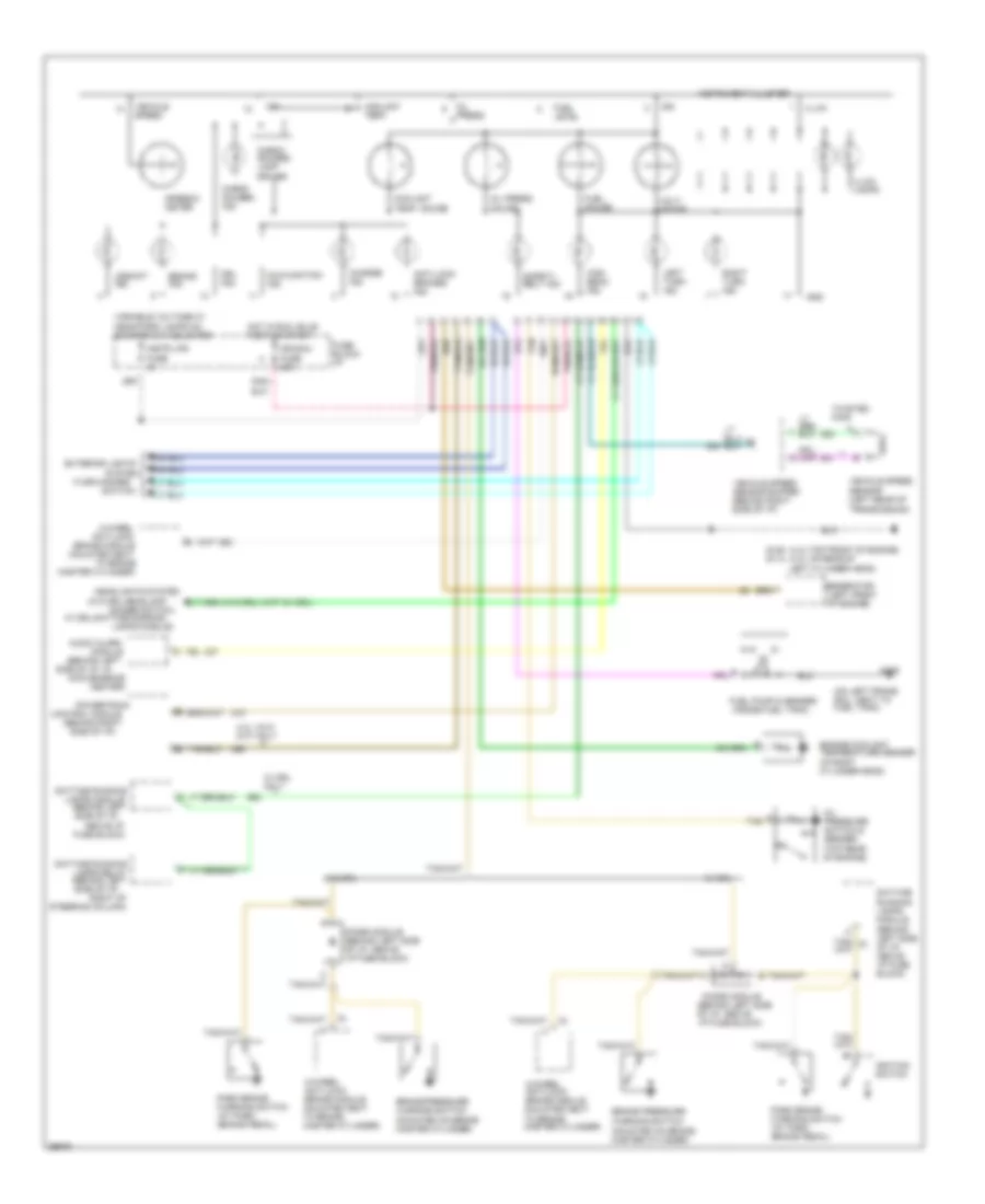
Analog Cluster Wiring Diagram for GMC Jimmy 1994
 https://portal-diagnostov.com/license.html
Automotive Electricians Portal FZCO
Automotive Electricians Portal FZCO
https://portal-diagnostov.com/license.html
https://portal-diagnostov.com/license.html
Automotive Electricians Portal FZCO
Automotive Electricians Portal FZCO
List of elements for Analog Cluster Wiring Diagram for GMC Jimmy 1994:
- (4.3l-top front of engine) (4.3l hp-rear of
- (behind left
- (behind left side of i/p,
- (behind left side of i/p, above i/p fuse block)
- (behind right
- (inside fuel tank)
- (left front of engine)
- (mounted on brake master cylinder)
- (on left frame rail, next to fuel tank)
- (top rear of engine)
- (turn-hazard
- (w/o drl-headlamp
- 4-wheel
- 4-wheel anti-lock brake module (mounted next to brake master cylinder)
- 4.3l vin z (m/t) only
- Above i/p
- Anti-lock
- Anti-lock brakes ind.
- Audio alarm
- Brake ind.
- Brake module (mounted next
- Brake pressure warning switch
- Center)
- Charge ind.
- Check gauges ind.
- Check gauges lamp driver
- Control module
- Convenience
- Coolant temp.
- Coolant temp. gauge
- Daytime
- Daytime running
- Dimmer switch;
- Diode module
- Diode module (behind left side of i/p, above i/p fuse block)
- Drl ind.
- Engine coolant temperature sender (in right cylinder head)
- Exterior lights
- Fuel gauge
- Fuel level
- Fuel pump & sender
- Fuse block)
- Fuse block: i/p
- G125 g114
- G409
- Generator
- Gnd
- Headlights system
- High beam ind.
- Hot in run, bulb test or start
- Ign
- Ign/gau fuse 20a
- Ignition switch
- Illum.
- Illum. lamps
- Instr lps fuse 5a
- Instrument cluster
- Lamps module
- Lamps module)
- Lamps relay (behind left side of i/p,
- Left cylinder head)
- Left turn ind.
- Malfunction ind.
- Master cylinder)
- Module
- Oil press.
- Oil press. gauge
- Oil pressure switch & sender
- Park brake warning switch (at park brake pedal)
- Powertrain
- Right of
- Right turn ind.
- Running lamps module (behind left side of i/p, above i/p fuse block)
- Safety belt ind.
- Side of i/p)
- Side of i/p, in
- Speedo- meter
- Steering column)
- Switch)
- System
- Tan
- To brake
- Twisted pair
- Upshift ind.
- Variable voltage w/ head/park lamps on & dimmer sw adjusted
- Vehicle speed
- Vehicle speed sensor (left rear of transmission)
- Vehicle speed sensor buffer (behind right side of i/p)
- Volt- meter
- W/ drl
- W/ drl only
- W/ drl-daytime running
- W/o drl
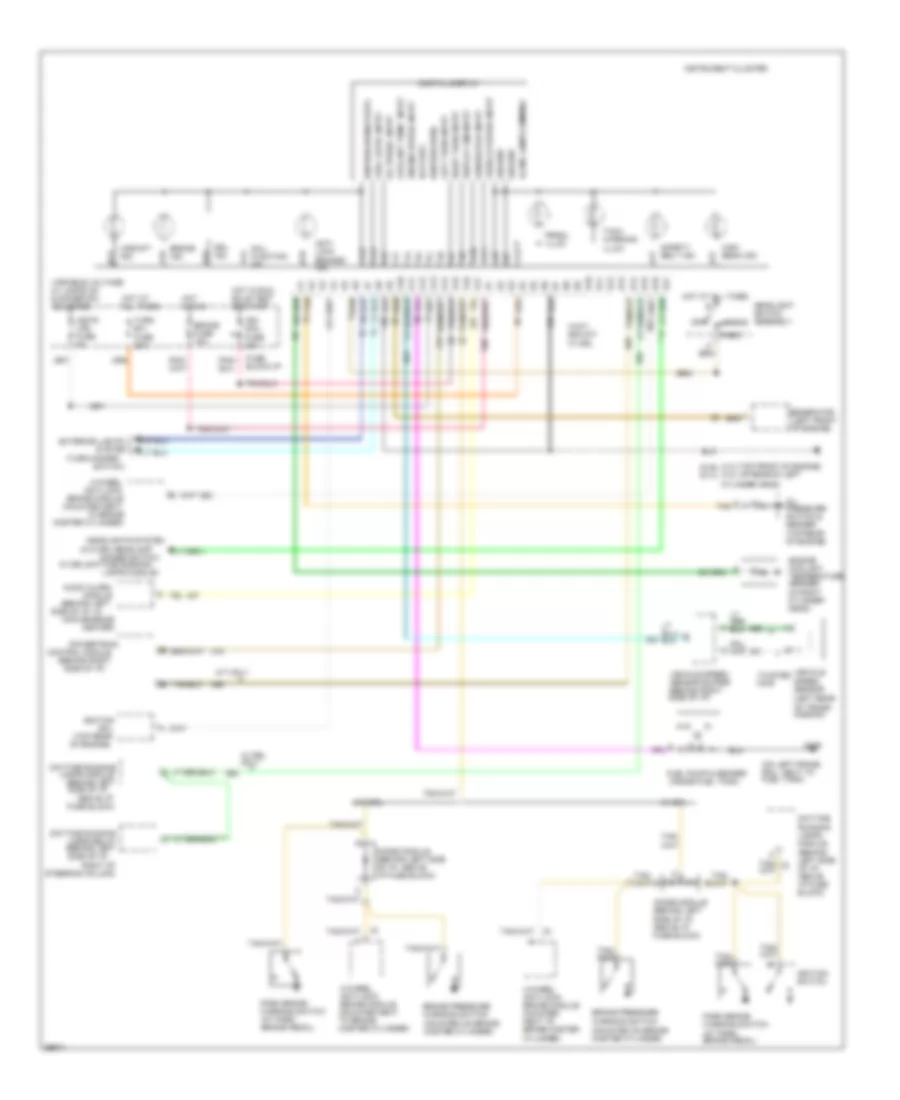
Electronic Cluster Wiring Diagram for GMC Jimmy 1994
 https://portal-diagnostov.com/license.html
Automotive Electricians Portal FZCO
Automotive Electricians Portal FZCO
https://portal-diagnostov.com/license.html
https://portal-diagnostov.com/license.html
Automotive Electricians Portal FZCO
Automotive Electricians Portal FZCOList of elements for Electronic Cluster Wiring Diagram for GMC Jimmy 1994:
- (4.3l-top front of engine) (4.3l hp-rear of left
- (behind left
- (behind left side of i/p,
- (behind right
- (inside fuel tank)
- (left front of engine)
- (mounted on brake master cylinder)
- (on left frame rail, next to fuel tank)
- (top rear of engine)
- (turn-hazard
- (w/o drl-headlamp
- 4-wheel
- 4-wheel anti-lock brake module (mounted next to brake master
- 4-wheel anti-lock brake module (mounted next to brake master cylinder)
- A10
- A11
- A12
- A13
- A14
- A15
- A16
- A17
- Above i/p
- Anti- lock brakes ind.
- Anti-lock
- Audio alarm
- B10
- B11
- B12
- B13
- B14
- B15
- B16
- B17
- Battery
- Brake fuse 15a
- Brake ind.
- Brake module (mounted next
- Brake pressure warning switch
- Center)
- Coil
- Control module
- Convenience
- Coolant temp. input
- Cylinder head)
- Cylinder)
- Daytime
- Daytime running
- Digital display
- Dimmer switch;
- Diode module (behind left side of i/p, above i/p fuse block)
- Display dim input
- Drl ind.
- Engine coolant temperature sender (in right cylinder head)
- Engine speed input
- Exterior lights
- Fuel level input
- Fuel pump & sender
- Fuse block)
- Fuse block:i/p
- G125 g114
- G409
- Generator
- Generator input
- Ground
- Head
- Headlight switch assembly
- Headlights system
- High beam ind.
- Hot at all times
- Hot in run
- Hot in run, bulb test or start
- Ign/ gau fuse 20a
- Ignition
- Ignition (run)
- Ignition (run/start)
- Ignition switch
- Illum. lamps dimming
- Instr lps fuse 5a
- Instrument cluster
- Lamps module
- Lamps module)
- Lamps relay (behind left side of i/p,
- Left turn input
- M/t only
- Mal- function ind.
- Master cylinder)
- Module
- Off
- Oil press. input
- Oil pressure switch & sender
- Park
- Park brake warning switch (at park brake pedal)
- Powertrain
- Prndl illum.
- Right of
- Right turn input
- Running lamps module (behind left side of i/p, above i/p fuse block)
- Safety belt ind.
- Side of i/p)
- Side of i/p, in
- Speed sensor (left rear of trans- mission)
- Steering column)
- Switch)
- System
- Tach warning illum.
- Tan
- To brake
- Turn b/u fuse 20a
- Twisted pair
- Upshift ind.
- Variable voltage w/ lamps on & dimmer sw adjusted
- Vehicle
- Vehicle speed input
- Vehicle speed sensor buffer (behind right side of i/p)
- W/ drl
- W/ drl only
- W/ drl-daytime running
- W/o drl

 Čeština
 Dansk
Dansk Deutsch
 Ελληνικά
 English
 English
 Español
 Suomi
Suomi Français
 Français
 עברית
עברית Hrvatski
 Magyar
 Italiano
 日本語
日本語 한국어
한국어 Nederlands
 Polski
 Português
 Português
 Română
 Русский
 Slovenčina
 Slovenščina
 Svenska
 Türkçe
