POWER DISTRIBUTION
3.8L VIN 2
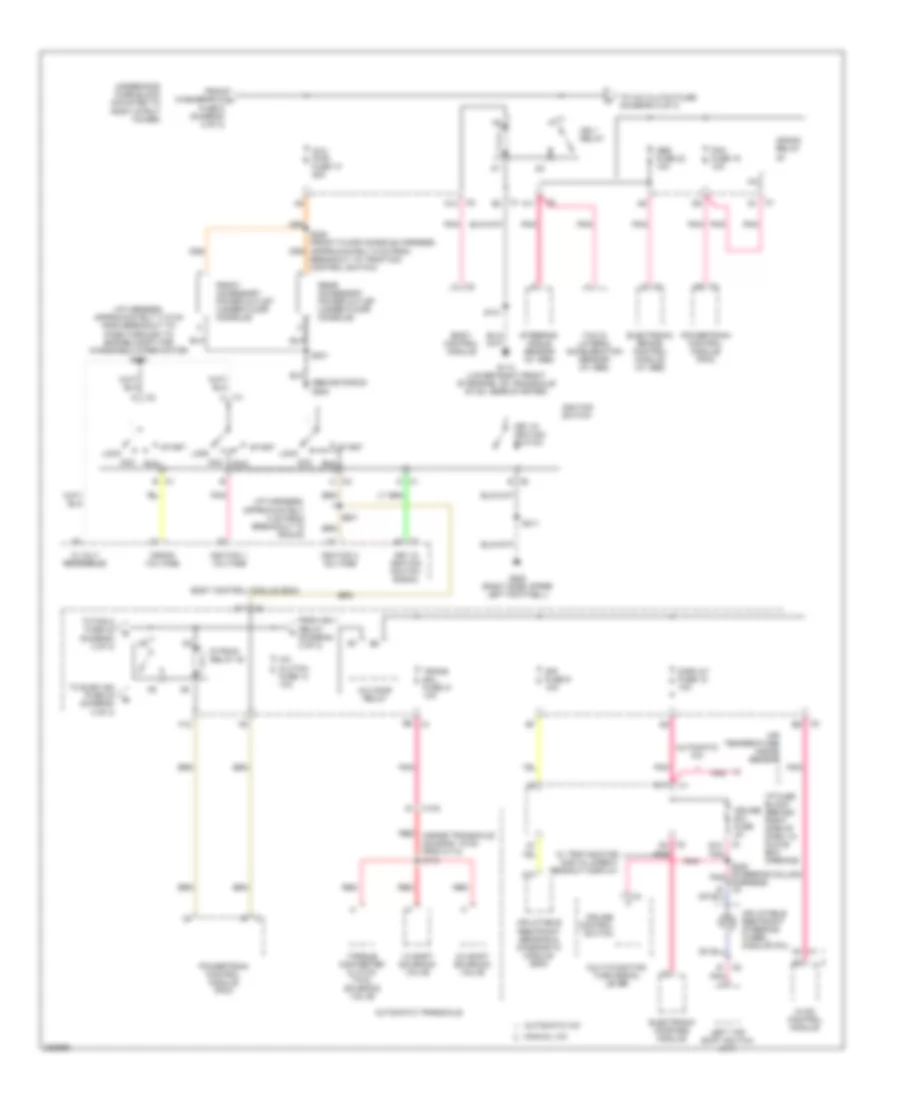
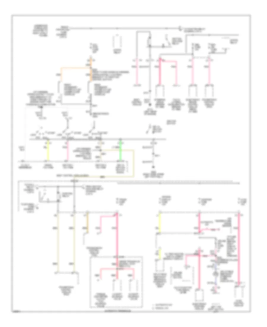
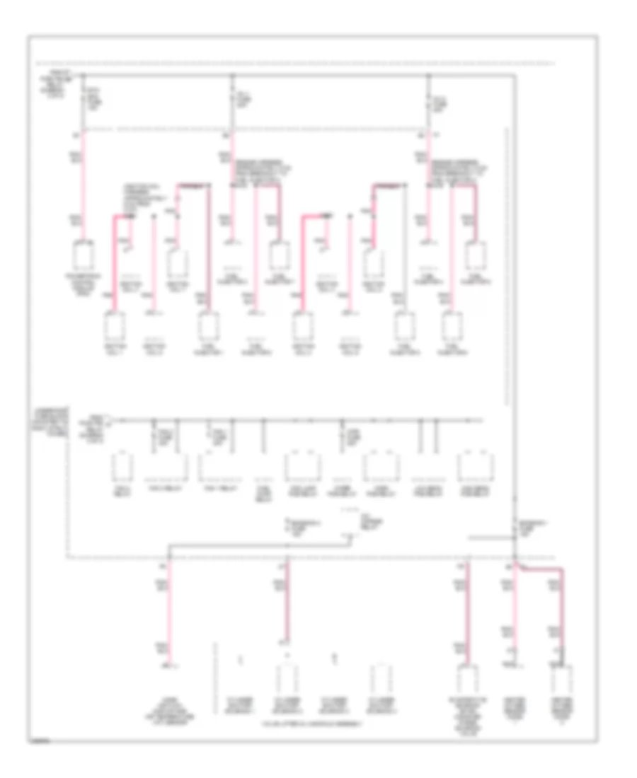
3.8L VIN 2, Power Distribution Wiring Diagram (1 of 3) for Pontiac Grand Prix GXP 2006
 https://portal-diagnostov.com/license.html
Automotive Electricians Portal FZCO
Automotive Electricians Portal FZCO
https://portal-diagnostov.com/license.html
https://portal-diagnostov.com/license.html
Automotive Electricians Portal FZCO
Automotive Electricians Portal FZCO
List of elements for 3.8L VIN 2, Power Distribution Wiring Diagram (1 of 3) for Pontiac Grand Prix GXP 2006:
- (approximately 4.5 cm from breakout to seat lumbar switch) s331
- (behind right side of dash, in glove box opening) i/p fuse block
- (mounted to right strut tower) underhood fuse block
- (not used)
- Abs mtr fuse 31 40a
- Abs sol fuse 19 25a
- Air pump fuse 56 50a
- Audio amplifier (w/ 8 speaker system)
- Automatic a/c
- B1 c1
- B10
- Batt main 1 fuse 26 40a
- Batt main 2 fuse 27 50a
- Batt main 3 fuse 28 40a
- Batt main 4 fuse 30 30a
- Battery
- Blower motor control processor
- Body control module (bcm)
- C1 a1
- C1 b
- C1 e
- C2 b
- C2 d9
- C2 e2
- C2 f9
- C4 c2
- Canister fuse 10a
- Chmsl/ bkup fuse 15a
- D10
- D12 c1
- Data link connector (dlc)
- Digital radio receiver (w/ digital audio system s-band)
- Displays fuse 10a
- Dr lk/ trunk fuse 15a
- Driver heated seat relay (if equipped)
- Driver information center (dic)
- Driver seat adjuster switch
- Driver seat lumbar switch
- Driver window switch
- E12
- Early production
- Electronic brake control module (ebcm) (w/ abs)
- Evaporative emission (evap) canister vent solenoid
- F10
- Front passenger inflatable restraint pressure system (pps) module
- Generator
- Head up display (hud)
- Htd seat fuse 20a
- Hvac control module
- Hvac fuse 10a
- If equipped
- Instrument panel cluster (ipc)
- Int light fuse 10a
- Late production
- Manual a/c
- Onstar/ aldl fuse 10a
- Out side rear- view mirror switch
- Passenger front heated seat relay (if equipped)
- Passenger front window switch
- Pcm/ etc fuse 16 15a
- Pk lamps fuse 10a
- Pk lp relay
- Power lumbar control seat
- Powertrain control module (pcm)
- Pwr mirs fuse 10a
- Pwr seat circuit breaker 25a
- Pwr wdo circuit breaker 25a
- Radio
- Radio/ amp fuse 25a
- Rap relay
- Red
- Remote control door lock receiver (rcdlr)
- Rfa/ mod fuse 10a
- Rr defog relay
- Secondary air injection (air) pump relay (sulev)
- Starter
- Sun roof fuse 20a
- Sun roof module
- To aux pwr fuse 10 (diagram 2 of 3)
- Turn/ haz fuse 20a
- Vehicle communication interface module (vcim) (if equipped)
- W/ driver
- W/o driver
- Washer/ rvc fuse 6 15a
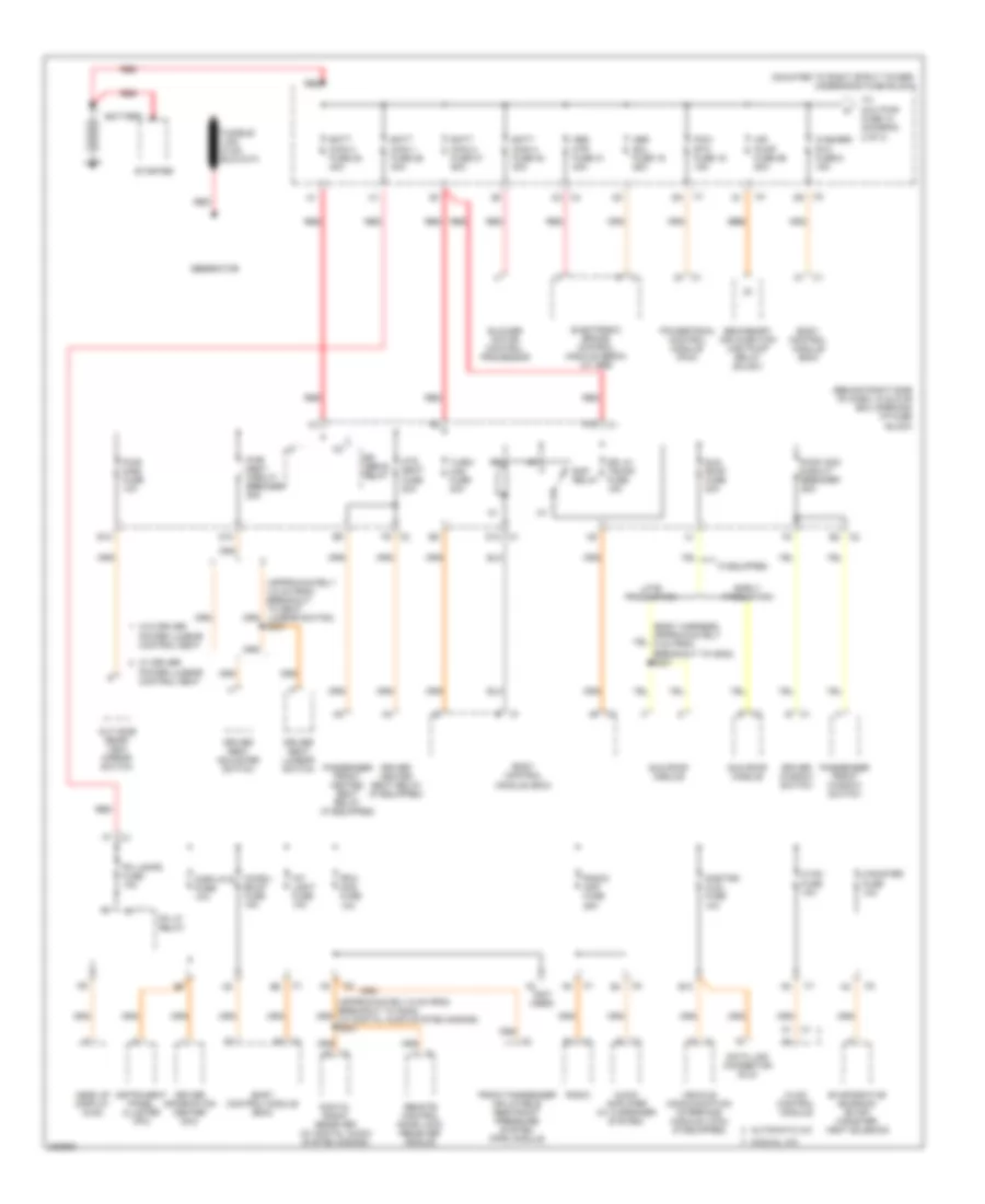
3.8L VIN 2, Power Distribution Wiring Diagram (2 of 3) for Pontiac Grand Prix GXP 2006
 https://portal-diagnostov.com/license.html
Automotive Electricians Portal FZCO
Automotive Electricians Portal FZCO
https://portal-diagnostov.com/license.html
https://portal-diagnostov.com/license.html
Automotive Electricians Portal FZCO
Automotive Electricians Portal FZCOList of elements for 3.8L VIN 2, Power Distribution Wiring Diagram (2 of 3) for Pontiac Grand Prix GXP 2006:
- (behind radio) g200
- (i/p harness, approximately 17.5 cm from breakout to pass-through to engine compt for windshield wiper motor) s200
- (i/p harness, approximately 4 cm from breakout to rcdlr)
- 1-2 shift solenoid valve
- 12 volt reference
- 2-3 shift solenoid valve
- A/c clutch fuse 13 10a
- A/c comp relay
- A10
- A11
- Abs fuse 23 10a
- Acc
- Air temperature inside sensor
- Automatic a/c
- Automatic transaxle
- Aux pwr fuse 10 25a
- Body control module
- Body control module (bcm)
- Breakout to traction control switch)
- C c2
- C1 a2
- C1 b
- C1 b3
- C1 d
- C1 d1
- C100
- C2 a12
- C2 d11
- C2 d2
- Crank relay
- Crank voltage
- Cruise control switch
- Cruise sw fuse 2a
- D11
- Display fuse 18 10a
- E c2
- E12
- Electronic brake control module (w/ abs)
- Electronic compass module
- F12
- From ign 1 relay (diagram 2 of 3)
- From washer/rvc a fuse 6 (diagram 2 of 3)
- Front accessory power outlet (under floor console)
- G113 (lower right front of engine, on transaxle stud, near starter)
- G202 (right side upper left footwell)
- Hvac control module
- I/p fuse block (behind right side of dash, in glove box opening)
- Ign 1 relay
- Ignition 1 voltage
- Ignition 3 voltage
- Ignition switch
- Inflatable restraint sensing & diagnostic module (sdm)
- Inflatable restraint steering wheel module coil
- Key in ignition switch
- Key in ignition switch signal
- Left tap shift switch (a/t)
- Lock
- Manual a/c
- Multi-function turn signal lever
- P/train relay 40
- Pcm fuse 15 10a
- Pnk
- Powertrain control module (pcm)
- Rear accessory power outlet (under floor console)
- Red
- Red (inside transaxle housing, 19 cm from c113) s115
- Run
- S101
- S201
- S211
- S231
- S240 (steering column pnk harness) c4
- Sir fuse 9 10a
- Start
- Steering angle sensor (w/ abs)
- To a/c clutch fuse (diagram 2 of 3)
- To elek ign fuse 24 (diagram 3 of 3)
- To fan 2 fuse 32 (diagram 3 of 3)
- Torque converter clutch (tcc) solenoid valve
- Trans sol fuse 21 10a
- Underhood fuse block (mounted to right strut tower)
- W/ trip monitor digital direct readout display
- Yaw & lateral acceleration sensor (w/ abs)
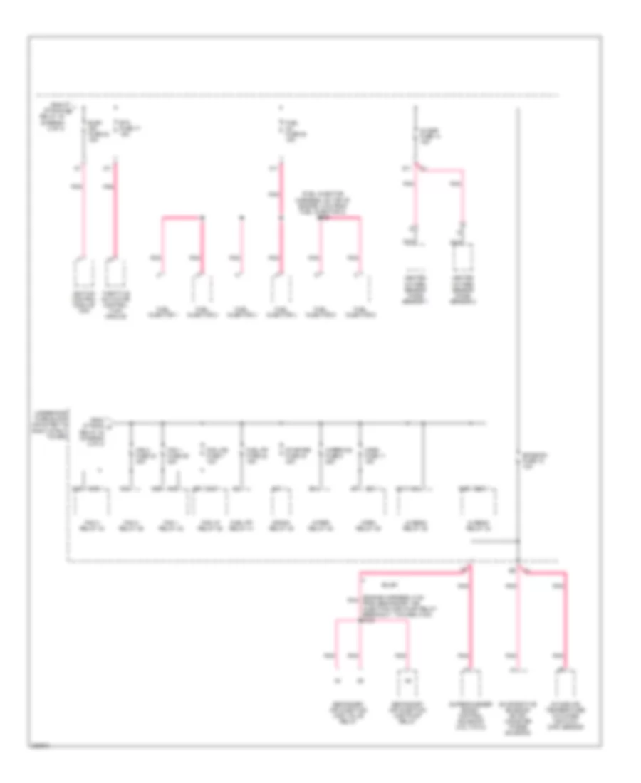
3.8L VIN 2, Power Distribution Wiring Diagram (3 of 3) for Pontiac Grand Prix GXP 2006
 https://portal-diagnostov.com/license.html
Automotive Electricians Portal FZCO
Automotive Electricians Portal FZCO
https://portal-diagnostov.com/license.html
https://portal-diagnostov.com/license.html
Automotive Electricians Portal FZCO
Automotive Electricians Portal FZCOList of elements for 3.8L VIN 2, Power Distribution Wiring Diagram (3 of 3) for Pontiac Grand Prix GXP 2006:
- (engine harness, 5 cm pnk from secondary air injection (air) pump relay breakout, toward c100) s103
- (fuel injector harness, on top of engine, 2 cm from fuel injector 2) s109
- 02 ssr fuse 14 15a
- A11
- A12
- A18
- A19
- C10
- C11
- Crank relay 48
- D11
- E14
- Elek ign fuse 24 15a
- Emission fuse 12 10a
- Etc fuse 17 15a
- Evaporative emission (evap) canister purge solenoid
- Fan 1 fuse 29 30a
- Fan 1 relay 42
- Fan 2 fuse 32 30a
- Fan 2 relay 46
- Fan 3 relay 43
- Fog lp relay 36
- Fog lps fuse 7 10a
- From p/train b relay 40 (diagram 2 of 3)
- From p/train d relay 40 (diagram 2 of 3)
- Fuel inj fuse 20 15a
- Fuel injector 1
- Fuel injector 2
- Fuel injector 3
- Fuel injector 4
- Fuel injector 5
- Fuel injector 6
- Fuel pp fuse 22 15a
- Fuel pp relay 41
- G19
- G20
- Heated oxygen sensor (ho2s) sensor 1
- Heated oxygen sensor (ho2s) sensor 2
- Hi beam relay 34
- Horn fuse 11 15a
- Horn relay 39
- Ignition control module (icm)
- Intake air temperature (iat)/mass air flow (maf) sensor
- K15
- K18
- K19
- Lo beam relay 35
- Nca
- Pnk
- Secondary air injection (air) pump relay
- Secondary air injection (air) valve relay
- Starter fuse 33 40a
- Sulev
- Supercharger boost control solenoid (3.8l (vin 4))
- Throttle actuator control (tac) module
- Underhood fuse block (mounted to right strut tower)
- Wiper relay 45
- Wiper/ws fuse 5 25a
3.8L VIN 4
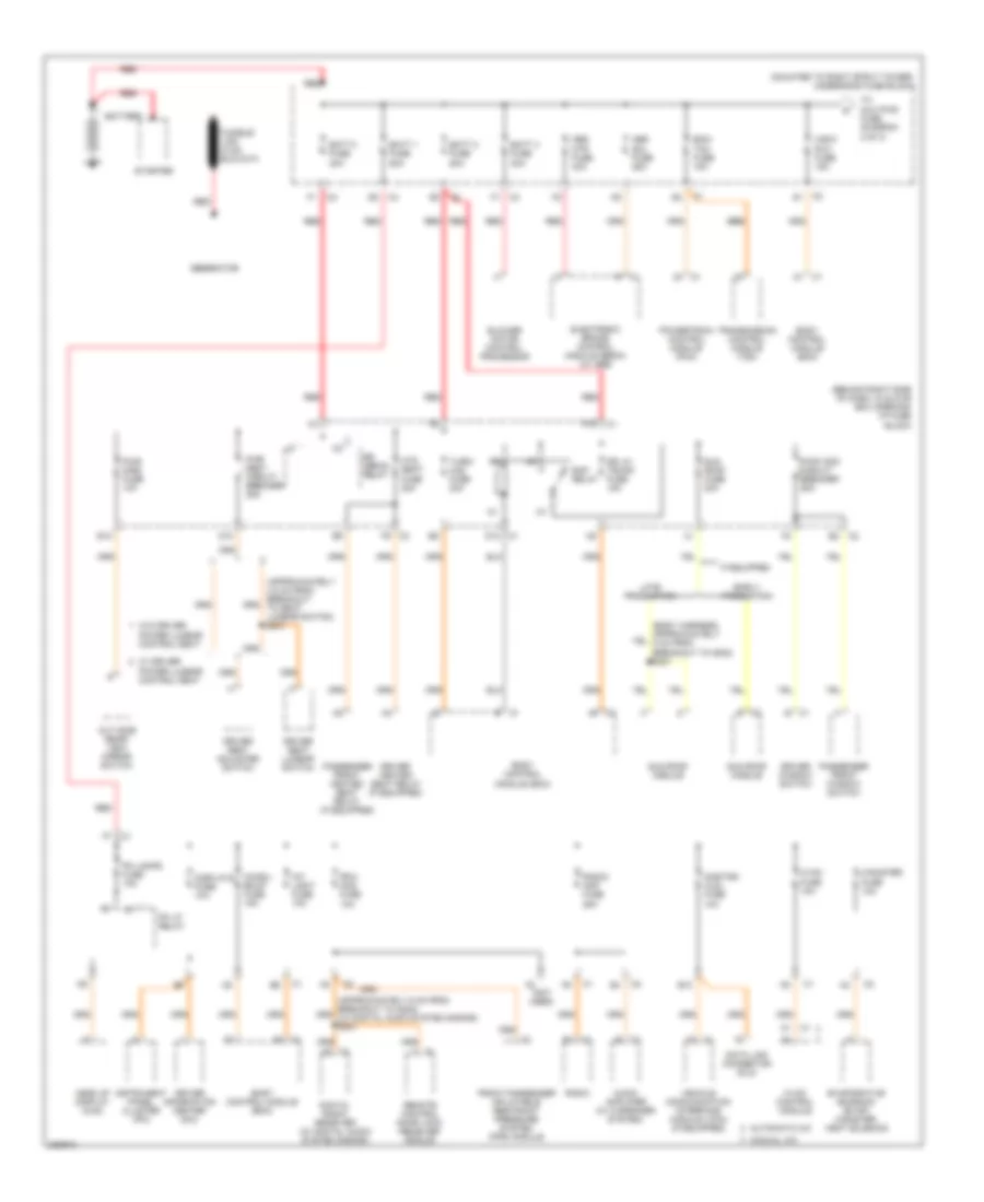
3.8L VIN 4, Power Distribution Wiring Diagram (1 of 3) for Pontiac Grand Prix GXP 2006
 https://portal-diagnostov.com/license.html
Automotive Electricians Portal FZCO
Automotive Electricians Portal FZCO
https://portal-diagnostov.com/license.html
https://portal-diagnostov.com/license.html
Automotive Electricians Portal FZCO
Automotive Electricians Portal FZCOList of elements for 3.8L VIN 4, Power Distribution Wiring Diagram (1 of 3) for Pontiac Grand Prix GXP 2006:
- (approximately 4.5 cm from breakout to seat lumbar switch) s331
- (behind right side of dash, in glove box opening) i/p fuse block
- (mounted to right strut tower) underhood fuse block
- (not used)
- Abs mtr fuse 31 40a
- Abs sol fuse 19 25a
- Air pump fuse 56 50a
- Audio amplifier (w/ 8 speaker system)
- Automatic a/c
- B1 c1
- B10
- Batt main 1 fuse 26 40a
- Batt main 2 fuse 27 50a
- Batt main 3 fuse 28 40a
- Batt main 4 fuse 30 30a
- Battery
- Blower motor control processor
- Body control module (bcm)
- C1 a1
- C1 b
- C1 e
- C2 b
- C2 d9
- C2 e2
- C2 f9
- C4 c2
- Canister fuse 10a
- Chmsl/ bkup fuse 15a
- D10
- D12 c1
- Data link connector (dlc)
- Digital radio receiver (w/ digital audio system s-band)
- Displays fuse 10a
- Dr lk/ trunk fuse 15a
- Driver heated seat relay (if equipped)
- Driver information center (dic)
- Driver seat adjuster switch
- Driver seat lumbar switch
- Driver window switch
- E12
- Early production
- Electronic brake control module (ebcm) (w/ abs)
- Evaporative emission (evap) canister vent solenoid
- F10
- Front passenger inflatable restraint pressure system (pps) module
- Generator
- Head up display (hud)
- Htd seat fuse 20a
- Hvac control module
- Hvac fuse 10a
- If equipped
- Instrument panel cluster (ipc)
- Int light fuse 10a
- Late production
- Manual a/c
- Onstar/ aldl fuse 10a
- Out side rear- view mirror switch
- Passenger front heated seat relay (if equipped)
- Passenger front window switch
- Pcm/ etc fuse 16 15a
- Pk lamps fuse 10a
- Pk lp relay
- Power lumbar control seat
- Powertrain control module (pcm)
- Pwr mirs fuse 10a
- Pwr seat circuit breaker 25a
- Pwr wdo circuit breaker 25a
- Radio
- Radio/ amp fuse 25a
- Rap relay
- Red
- Remote control door lock receiver (rcdlr)
- Rfa/ mod fuse 10a
- Rr defog relay
- Secondary air injection (air) pump relay (sulev)
- Starter
- Sun roof fuse 20a
- Sun roof module
- To aux pwr fuse 10 (diagram 2 of 3)
- Turn/ haz fuse 20a
- Vehicle communication interface module (vcim) (if equipped)
- W/ driver
- W/o driver
- Washer/ rvc fuse 6 15a
3.8L VIN 4, Power Distribution Wiring Diagram (2 of 3) for Pontiac Grand Prix GXP 2006
 https://portal-diagnostov.com/license.html
Automotive Electricians Portal FZCO
Automotive Electricians Portal FZCO
https://portal-diagnostov.com/license.html
https://portal-diagnostov.com/license.html
Automotive Electricians Portal FZCO
Automotive Electricians Portal FZCOList of elements for 3.8L VIN 4, Power Distribution Wiring Diagram (2 of 3) for Pontiac Grand Prix GXP 2006:
- (behind radio) g200
- (i/p harness, approximately 17.5 cm from breakout to pass-through to engine compt for windshield wiper motor) s200
- (i/p harness, approximately 4 cm from breakout to rcdlr)
- 1-2 shift solenoid valve
- 12 volt reference
- 2-3 shift solenoid valve
- A/c clutch fuse 13 10a
- A/c comp relay
- A10
- A11
- Abs fuse 23 10a
- Acc
- Air temperature inside sensor
- Automatic a/c
- Automatic transaxle
- Aux pwr fuse 10 25a
- Body control module
- Body control module (bcm)
- Breakout to traction control switch)
- C c2
- C1 a2
- C1 b
- C1 b3
- C1 d
- C1 d1
- C100
- C2 a12
- C2 d11
- C2 d2
- Crank relay
- Crank voltage
- Cruise control switch
- Cruise sw fuse 2a
- D11
- Display fuse 18 10a
- E c2
- E12
- Electronic brake control module (w/ abs)
- Electronic compass module
- F12
- From ign 1 relay (diagram 2 of 3)
- From washer/rvc a fuse 6 (diagram 2 of 3)
- Front accessory power outlet (under floor console)
- G113 (lower right front of engine, on transaxle stud, near starter)
- G202 (right side upper left footwell)
- Hvac control module
- I/p fuse block (behind right side of dash, in glove box opening)
- Ign 1 relay
- Ignition 1 voltage
- Ignition 3 voltage
- Ignition switch
- Inflatable restraint sensing & diagnostic module (sdm)
- Inflatable restraint steering wheel module coil
- Key in ignition switch
- Key in ignition switch signal
- Left tap shift switch (a/t)
- Lock
- Manual a/c
- Multi-function turn signal lever
- P/train relay 40
- Pcm fuse 15 10a
- Pnk
- Powertrain control module (pcm)
- Rear accessory power outlet (under floor console)
- Red
- Red (inside transaxle housing, 19 cm from c113) s115
- Run
- S101
- S201
- S211
- S231
- S240 (steering column pnk harness) c4
- Sir fuse 9 10a
- Start
- Steering angle sensor (w/ abs)
- To a/c clutch fuse (diagram 2 of 3)
- To elek ign fuse 24 (diagram 3 of 3)
- To fan 2 fuse 32 (diagram 3 of 3)
- Torque converter clutch (tcc) solenoid valve
- Trans sol fuse 21 10a
- Underhood fuse block (mounted to right strut tower)
- W/ trip monitor digital direct readout display
- Yaw & lateral acceleration sensor (w/ abs)
3.8L VIN 4, Power Distribution Wiring Diagram (3 of 3) for Pontiac Grand Prix GXP 2006
 https://portal-diagnostov.com/license.html
Automotive Electricians Portal FZCO
Automotive Electricians Portal FZCO
https://portal-diagnostov.com/license.html
https://portal-diagnostov.com/license.html
Automotive Electricians Portal FZCO
Automotive Electricians Portal FZCOList of elements for 3.8L VIN 4, Power Distribution Wiring Diagram (3 of 3) for Pontiac Grand Prix GXP 2006:
- (engine harness, 5 cm pnk from secondary air injection (air) pump relay breakout, toward c100) s103
- (fuel injector harness, on top of engine, 2 cm from fuel injector 2) s109
- 02 ssr fuse 14 15a
- A11
- A12
- A18
- A19
- C10
- C11
- Crank relay 48
- D11
- E14
- Elek ign fuse 24 15a
- Emission fuse 12 10a
- Etc fuse 17 15a
- Evaporative emission (evap) canister purge solenoid
- Fan 1 fuse 29 30a
- Fan 1 relay 42
- Fan 2 fuse 32 30a
- Fan 2 relay 46
- Fan 3 relay 43
- Fog lp relay 36
- Fog lps fuse 7 10a
- From p/train b relay 40 (diagram 2 of 3)
- From p/train d relay 40 (diagram 2 of 3)
- Fuel inj fuse 20 15a
- Fuel injector 1
- Fuel injector 2
- Fuel injector 3
- Fuel injector 4
- Fuel injector 5
- Fuel injector 6
- Fuel pp fuse 22 15a
- Fuel pp relay 41
- G19
- G20
- Heated oxygen sensor (ho2s) sensor 1
- Heated oxygen sensor (ho2s) sensor 2
- Hi beam relay 34
- Horn fuse 11 15a
- Horn relay 39
- Ignition control module (icm)
- Intake air temperature (iat)/mass air flow (maf) sensor
- K15
- K18
- K19
- Lo beam relay 35
- Nca
- Pnk
- Secondary air injection (air) pump relay
- Secondary air injection (air) valve relay
- Starter fuse 33 40a
- Sulev
- Supercharger boost control solenoid (3.8l (vin 4))
- Throttle actuator control (tac) module
- Underhood fuse block (mounted to right strut tower)
- Wiper relay 45
- Wiper/ws fuse 5 25a
5.3L VIN C
5.3L VIN C, Power Distribution Wiring Diagram (1 of 3) for Pontiac Grand Prix GXP 2006
 https://portal-diagnostov.com/license.html
Automotive Electricians Portal FZCO
Automotive Electricians Portal FZCO
https://portal-diagnostov.com/license.html
https://portal-diagnostov.com/license.html
Automotive Electricians Portal FZCO
Automotive Electricians Portal FZCOList of elements for 5.3L VIN C, Power Distribution Wiring Diagram (1 of 3) for Pontiac Grand Prix GXP 2006:
- (behind right side of dash, in glove box opening) i/p fuse block
- (mounted to right strut tower) underhood fuse block
- (not used)
- A1 c1
- Abs mtr fuse 40a
- Abs sol fuse 25a
- Audio amplifier (w/ 8 speaker system)
- Automatic a/c
- B c1
- B c2
- B10
- Batt 1 fuse 50a
- Batt 2 fuse 50a
- Batt 3 fuse 40a
- Batt 4 fuse 30a
- Battery
- Blower motor control processor
- Body control module (bcm)
- C1 b1
- C2 g1
- C4 f1
- Canister fuse 10a
- Chmsl/ bkup fuse 15a
- D10
- D12 c1
- Data link connector (dlc)
- Digital radio receiver (w/ digital audio system s-band)
- Displays fuse 10a
- Dr lk/ trunk fuse 15a
- Driver heated seat relay (if equipped)
- Driver information center (dic)
- Driver seat adjuster switch
- Driver seat lumbar switch
- Driver window switch
- E c1
- E12
- E2 c2
- Early production
- Ecm/ tcm fuse 15a
- Electronic brake control module (ebcm) (w/ abs)
- Evaporative emission (evap) canister vent solenoid
- F10
- F9 c2
- Front passenger inflatable restraint pressure system (pps) module
- Generator
- Head up display (hud)
- Htd seat fuse 20a
- Hvac control module
- Hvac fuse 10a
- If equipped
- Instrument panel cluster (ipc)
- Int light fuse 10a
- Late production
- Manual a/c
- Onstar/ aldl fuse 10a
- Out side rear- view mirror switch
- Passenger front heated seat relay (if equipped)
- Passenger front window switch
- Pk lamps fuse 10a
- Pk lp relay
- Power lumbar control seat
- Powertrain control module (pcm)
- Pwr mirs fuse 10a
- Pwr seat circuit breaker 25a
- Pwr wdo circuit breaker 25a
- Radio
- Radio/ amp fuse 25a
- Rap relay
- Red
- Remote control door lock receiver (rcdlr)
- Rfa/ mod fuse 10a
- Rr defog relay
- Starter
- Sun roof fuse 20a
- Sun roof module
- To aux pwr fuse (diagram 2 of 3)
- Transmission control module (tcm)
- Turn/ haz fuse 20a
- Vehicle communication interface module (vcim) (if equipped)
- W/ driver
- W/o driver
- Wsw/ rvc fuse 15a
5.3L VIN C, Power Distribution Wiring Diagram (2 of 3) for Pontiac Grand Prix GXP 2006
 https://portal-diagnostov.com/license.html
Automotive Electricians Portal FZCO
Automotive Electricians Portal FZCO
https://portal-diagnostov.com/license.html
https://portal-diagnostov.com/license.html
Automotive Electricians Portal FZCO
Automotive Electricians Portal FZCOList of elements for 5.3L VIN C, Power Distribution Wiring Diagram (2 of 3) for Pontiac Grand Prix GXP 2006:
- (behind radio) g200
- (i/p harness, approximately 17.5 cm from breakout to pass-through to engine compt for windshield wiper motor) s200
- (i/p harness, approximately 4 cm from breakout to rcdlr)
- (inside transaxle housing, 19 cm red
- 1-2 shift solenoid valve
- 12 volt reference
- 2-3 shift solenoid valve
- A10
- A2 c1
- Abs fuse 10a
- Acc
- Air bag/ display fuse 10a
- Air temperature inside sensor
- Automatic a/c
- Automatic transaxle
- Aux pwr fuse 25a
- Body control module
- Body control module (bcm)
- Breakout to traction control switch)
- C c2
- C1 b
- C1 c2
- C1 j3
- C100
- C2 d2
- C2 e
- C2 h2
- Compass fuse 10a
- Crank voltage
- Cruise control switch
- Cruise sw fuse 2a
- D c1
- D11
- E12
- Ecm ign fuse 10a
- Electronic brake control module (ebcm) (w/ abs)
- Electronic compass module
- From c113) s115
- From ignition main pcb relay (diagram 2 of 3)
- From wsw/rvc a fuse (diagram 2 of 3)
- Front accessory power outlet (under floor console)
- G113 (left rear of engine)
- G202 (right side upper left footwell)
- Hvac control module
- Hvac fuse 10a
- I/p fuse block (behind right side of dash, in glove box opening)
- Ignition 1 voltage
- Ignition 3 voltage
- Ignition main pcb relay
- Ignition switch
- Inflatable restraint sensing & diagnostic module (sdm)
- Inflatable restraint steering wheel module coil
- Key in ignition switch
- Key in ignition switch signal
- Left tap shift switch (a/t)
- Lock
- Manual a/c
- Multi-function turn signal lever
- Pnk
- Powertrain control module (pcm)
- Pwr/trn relay
- Rear accessory power outlet (under floor console)
- Red
- Run
- S101
- S201
- S211
- S231
- S240 (steering column pnk harness) c4
- Start
- Steering angle sensor (w/ abs)
- Strtr relay
- To etc/ecm fuse (diagram 3 of 3)
- To fan 2 relay (diagram 3 of 3)
- To pwr/trn relay (diagram 2 of 3)
- Torque converter clutch (tcc) solenoid valve
- Trans fuse 10a
- Transmission control module (tcm)
- Underhood fuse block (mounted to right strut tower)
- W/ trip monitor digital direct readout display
- Yaw & lateral acceleration sensor (w/ abs)
5.3L VIN C, Power Distribution Wiring Diagram (3 of 3) for Pontiac Grand Prix GXP 2006
 https://portal-diagnostov.com/license.html
Automotive Electricians Portal FZCO
Automotive Electricians Portal FZCO
https://portal-diagnostov.com/license.html
https://portal-diagnostov.com/license.html
Automotive Electricians Portal FZCO
Automotive Electricians Portal FZCOList of elements for 5.3L VIN C, Power Distribution Wiring Diagram (3 of 3) for Pontiac Grand Prix GXP 2006:
- (ignition coil harness, approximately 6 cm from c107) s106
- A/c cmprsr relay
- Cylinder shutoff solenoid 1
- Cylinder shutoff solenoid 2
- Cylinder shutoff solenoid 3
- Cylinder shutoff solenoid 4
- Emission 1 fuse 15a
- Emission 2 fuse 15a
- Etc/ ecm fuse 15a
- Evaporative emission (evap) canister purge solenoid valve
- Fan 1 fuse 30a
- Fan 1 relay
- Fan 2 fuse 30a
- Fan 2 relay
- Fan 3 relay
- Fog lamp pcb relay
- From pwr/trn b relay (diagram 2 of 3)
- From pwr/trn d relay (diagram 2 of 3)
- Fuel injector 1
- Fuel injector 2
- Fuel injector 3
- Fuel injector 4
- Fuel injector 5
- Fuel injector 6
- Fuel injector 7
- Fuel injector 8
- Fuel pump relay
- Heated oxygen sensor (ho2s)
- High beam pcb relay
- Horn pcb relay
- Ignition coil 1
- Ignition coil 2
- Ignition coil 3
- Ignition coil 4
- Ignition coil 5
- Ignition coil 6
- Ignition coil 7
- Ignition coil 8
- Inj 1 fuse 20a
- Inj 2 fuse 20a
- Low beam pcb relay
- Mass air flow (maf)/intake air temperature (iat) sensor
- Nca
- Pnk
- Powertrain control module (pcm)
- S105
- Underhood fuse block (mounted to right strut tower)
- Valve lifter oil manifold assembly
- Wiper pcb relay
- Wpr fuse 25a

 Čeština
 Dansk
Dansk Deutsch
 Ελληνικά
 English
 English
 Español
 Suomi
Suomi Français
 Français
 עברית
עברית Hrvatski
 Magyar
 Italiano
 日本語
日本語 한국어
한국어 Nederlands
 Polski
 Português
 Português
 Română
 Русский
 Slovenčina
 Slovenščina
 Svenska
 Türkçe
